Chaos-induced transparency in an ultrahigh-Q optical microcavity
Abstract
We demonstrate experimentally a new form of induced transparency, i.e., chaos-induced transparency, in a slightly deformed microcavity which support both continuous chaotic modes and discrete regular modes with Q factors exceeding . When excited by a focused laser beam, the induced transparency in the transmission spectrum originates from the destructive interference of two parallel optical pathways: (i) directly refractive excitation of the chaotic modes, and (ii) excitation of the ultra-high-Q regular mode via chaos-assisted dynamical tunneling mechanism coupling back to the chaotic modes. By controlling the focal position of the laser beam, the induced transparency experiences a highly tunable Fano-like asymmetric lineshape. The experimental results are modeled by a quantum scattering theory and show excellent agreement. This chaos-induced transparency is accompanied by extremely steep normal dispersion, and may open up new possibilities a dramatic slow light behavior and a significant enhancement of nonlinear interactions.
pacs:
42.25.Bs, 42.50.Gy, 42.60.DaOver the past two decades, it is well known that optical properties of matter can be dramatically modified by using a secondary light beam. For instance, an opaque atomic medium is made transparent in the presence of a strong control beam, known as the unique phenomenon of electromagnetically induced transparency (EIT) Boller . EIT can be explained in terms of a dark superposition state, or alternatively, by destructive quantum interference of the transition probability amplitudes. The observation of nonabsorbing resonance accompanying with the extremely steep normal dispersion through atomic coherence represents a key feature of EIT, which has led to novel concepts and important consequences, such as freezing light, enhancing nonlinear interaction and lasing without inversion RMP2005 . These have thrust EIT to the forefront of experimental study in atomic physics during the last two decades.
It has been recently recognized and demonstrated that similar interference effects also occur in linear classical systems such as plasma Harries1996 ; Gad , electric circuits Litvak ; Alzar , photonic microresonators Smith2004 ; Maleki2004 ; Yanik2004 ; Poon2004 ; Xu2006 ; Totsuka2007 ; Yang2009 ; Xiao2012 ; Di2011 , various metamaterials Zhang2008 ; Zheludev ; Tassin ; Liu2009 ; Kekatpure ; Kurter ; Hatice ; Fan2012 ; Chen and optomechanical systems Painter ; Kippenberg , which bring the original quantum phenomena into the realm of classical optics. Remarkably, this all-optical form of induced transparency does not require naturally occurring resonances and could therefore be applied to previously inaccessible wavelength regions, and equally importantly, no strong pumping is necessary. With a dynamic control in photonic structures, the all-optical EIT even stores light on a chip at room temperature by breaking the delay-bandwidth limit Xu2007 . In this Letter, we demonstrate experimentally a new form of induced transparency in a slightly deformed optical microcavity on a silicon chip. The induced transparency originates from the chaos-assisted tunneling mechanism in the deformed cavity, and thus it is termed as chaos-induced transparency. This tunneling violates the classical law of ray reflection and represents a formal analogue to the dynamical tunneling known as a pure quantum mechanical phenomenon Davis1981 .
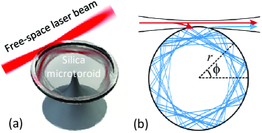
Figure 1 shows a schematic illustration of an on-chip deformed silica microtoroid excited by a free-space focused laser beam. In our experiment, the deformed microtoroid is fabricated from a --thickness silicon dioxide layer on a silicon wafer, which possesses a pre-designed boundary and ultra-smooth cavity surface by combining a CO2 laser reflow and a two-step dry etching process Jiang ; Vahala . The deformed microtoroid has the boundary defined as for , and for in the polar coordinates (, ), where denotes the deformation parameter related to the aspect ratio of the shape, and represents the size parameter. In our experiment, , , , , , and . Other than the intrinsic isotropy of emission in rotationally symmetric cavities, the deformed microtoroid supports both ultrahigh Q factors and highly directional emission toward far-field direction (emitted at polar angles and ) Jiang ; Zou . The underlying physics of highly directional emission lies in the dynamical tunneling Nature1997 ; Narimanov ; Song .
An important production of the aforementioned directional emission is that we can directly inject a laser beam into chaotic orbits of the deformed cavity with a time reversed way, and then the excitation light might be finally transferred to a target high-Q mode via the chaos-assisted dynamical tunneling An ; Park . As the tunneling is a wave-mechanical process, this transfer process would occur efficiently when the excitation light is on resonance with the target mode. In our experiment, a tunable laser beam is focused near the edge of the deformed microtoroid. The focused beam waist is smaller than m in diameter. The microcavity is mounted on a rotational stage with angular resolution and a translational stage with nm resolution, which allow a precise control of the coupling between the free-space beam and the microcavity by adjusting its incident far-field angle and the radial displacement relative to the local cavity boundary.
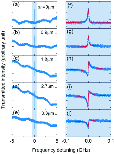
In the first experiment, the incident beam injects from far-field direction and focuses on the cavity edge at , and the collection of transmitted light is in far-field direction. Figure 2(a) with the zoom-in (f) shows a typical power transmission spectrum for a quasi-TM mode of the coupling system. It can be seen that the high-Q mode is eventually excited, and importantly, the sharp EIT-like resonance occurs. To test the dependence of the transparency resonance on the separation between the microcavity and the laser focal spot, transmission spectra are measured by radially moving the focused beam away from the cavity boundary, as shown in Figs. 2(b)-2(e) and 2(g)-2(j). Obviously, the EIT-like resonance experiences a transition to asymmetric Fano resonance Fano . The observation of Fano-like EIT resonance at the ultrahigh-Q cavity mode is attributed to the chaos-assisted dynamical tunneling in the deformed cavity, because such a high-Q mode can not be directly excited by a free-space beam due to the angular momentum mismatching between them.
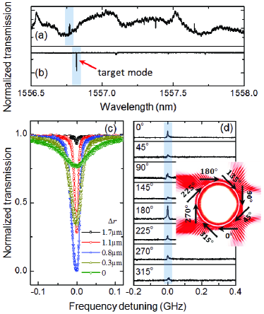
To further investigate the role of the dynamical tunneling, in the second experiment, we use a fiber taper (waist diameter m) to couple the deformed cavity. Figures 3(a)-3(b) compare the transmission spectra obtained with the two types of coupling methods. It can be seen that high-Q modes in both the spectra show a good correspondence where a minor red shift of modes occurs when coupled to the taper. The mode with the intrinsic quality factor exceeding at the wavelength of nm is the target mode throughout this paper. Remarkably, the EIT-like characteristic in the free-space transmission spectrum differs greatly from the symmetric Lorenzian dips (the dips are due to the cavity loss in the taper coupling). Moreover, no obvious change of the resonance lineshape is observed when the taper-cavity system is tuned continuously from under- to deep over-coupled regions, as depicted in Fig. 3(c). This is because that the taper directly excites high-Q modes (such as whispering gallery modes) instead of chaotic modes thanks to the angular momentum matching Vahala , and the dynamical tunneling between them essentially contributes to an additional energy decay for the high-Q modes in the present case. Even for the free-space coupling to the deformed cavity, the transparency resonances strongly depend on the excitation positions. As shown in Fig. 3(d), the highest transparency peak occurs when the incident beam focuses on the cavity edge at and from far-field direction. This is the exact position where high-Q counter-clockwise modes in the deformed cavity shows the strongest universal directional emission assisted by the chaos. In our experiment, we also measured the transmission spectra of an undeformed toroidal microcavity, and no Fano-like EIT resonance is observed with both the coupling methods because no chaotic mode is supported in the undeformed cavity.
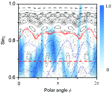
The physical mechanism of chaos-induced transparency is studied briefly in the following. The features of internal ray dynamics within the deformed microcavity can be well described in the phase space (Poincaré surface of section) Nature1997 ; Narimanov , as shown in black in Fig. 4. In this phase-space structure, ray dynamics is mostly chaotic, in addition to some regular orbits such as islands and Kalmorogov-Arnol’d-Moser (KAM) tori KAM . Classically, these different structures are disjoint. For instance, chaotic rays below the red KAM torus cannot couple into high-Q modes which are typically located on the upper of the phase space. This is verified by the chaotic trajectories shown as blue curves in Fig. 4, which cannot cross the KAM torus. However, in reality, the dynamical tunneling between the regular modes and neighboring chaotic orbits takes place. To demonstrate this, the sky-blue shadow in Fig. 4 plots the Husimi projection of the excited chaotic modes, representing the wave analog of the phase space. As expected, the most excitation field is distributing in the chaos region below the KAM torus, because the free-space beam refracts into the cavity and directly excites chaotic modes. Remarkably, some tails obviously intrude into the upper area by crossing the KAM torus. In particular, a strong tail at even reaches the top of the phase space where ultrahigh-Q modes are located. In other words, these ultrahigh-Q modes can be eventually excited via the chaos-assisted tunneling. As for the Fano-like EIT resonances, there exists two parallel excitation pathways: (1) direct excitation of the continuous chaotic modes from the incident beam, and (2) excitation of the high-Q mode via the chaos-assisted tunneling coupling back to the chaotic modes. These two pathways interfere with each other in the far field because a phase shift occurs when light crosses KAM tori which represents a potential barrier in wave-optic field.
We now theoretically model the experimental results in more details. In the free-space coupling process shown in Fig. 1, the incident light with frequency is scattered by the microcavity, and directly excites continuous chaotic modes, denoting the excitation state . We consider that a discrete regular mode with resonant frequency interacts with the chaotic states, and assume they are orthogonal An . The interacting system is governed by a Hamiltonian , satisfying , , and . Here describes the interaction between and , known as the dynamical tunneling; represents the modified decay rate of , consisting of (i) the intrinsic loss such as radiation, material absorption and scattering, and (ii) the chaos-assisted tunneling into the chaos other than the excitation state.
With a standard procedure developed by Fano in Ref. Fano , we obtain the transmission spectrum of the free-space beam
| (1) |
Here is defined as the ratio with being the coupling strength and representing the whole decay rate of the regular mode, where remains constant under the first Markov approximation QN ; describes the normalized detuning between the incident light and the regular mode; is a suitable transition operator between and , and describes the probability of transmitted signal Fano ; stands for the shape parameter of the transmission spectrum, where with denoting Cauchy’s principle value. To give a clear understanding, we consider two special cases as follows.
(i) If the dynamical tunneling between the regular and chaotic modes is absent, i.e., , the transmission spectrum in the absence of high-Q regular mode reduces to , known as unperturbed scattering due to in this case.
(ii) If the regular mode is over-coupled, i.e., and , the transmission spectrum yields a standard Fano resonance .
In experiments, the unperturbed transmission spectrum shows baseline oscillations in a large scanning range, similar to Refs. Poon2004 ; Yang2010 , which can be simply modeled by the interference of two amplitudes: (i) the directly transmitted amplitude , and (ii) the dissipated amplitude that refracts into and back from the cavity with an additional phase shift . Thus, the unperturbed transmission reads , and the shape parameter is simplified, given by , because the contribution of is negligible for a high-Q regular mode. As both and are determined, we can finally obtain the transmission spectrum in Eq. 1.
Under this model, the red solid curves in Figs. 2(f)-2(j) show the theoretical fittings, in good accordance with the experimental spectra (blue dots). From top to bottom, the transmission spectra experience a transition from the symmetric induced transparency to asymmetric line shape, predominantly due to the additional phase shift varying from to during this process. The fitting parameters and are plotted in Fig. 5(a). It can be seen that the coupling between the regular and the excitation states, described by the strength , becomes weaker when the focused beam moves away from the cavity boundary. This is possibly because that the direct refraction is less and the excited tends to distributes lower in the phase space. Furthermore, the modeled total decay rates of the regular mode range from to MHz, representing an invariant in our theory, which exactly fall within the error of the resonant linewidth measured by using the taper coupling method.
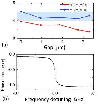
To characterize the chaos-induced transparency, finally, Fig. 5(b) shows the calculated phase change of the transmitted field with the modeled data in Fig. 2(f). This conventional curve exhibits an extremely steep normal dispersion, and indicates a strong suppression of the group velocity. At the resonance point , the group velocity is significantly reduced to smaller than where represents the velocity of light in vacuum, resulting from the ultra-narrow linewidth of the ultra-high-Q mode in the deformed microcavity.
In summary, we have experimentally demonstrated the chaos-induced transparency in a deformed microcavity with Q factor exceeding . A theoretical model is present and agrees well with the experimental results. When excited by a focused laser beam, the induced transparency in the transmission spectrum is attributed to the destructive interference of two parallel optical pathways either resonantly exciting the high-Q mode through the chaos-assisted tunneling or not. By controlling the excitation position of the laser beam, the induced transparency experiences a highly tunable Fano-like asymmetric lineshape. This chaos-induced transparency is accompanied by the extremely steep normal dispersion resulting from the ultrahigh-Q mode, which provides a dramatic slow light behavior and a significant enhancement of nonlinear interactions in the optical microcavity.
Acknowledgements.
Y.F.X. thanks Professor Kyungwon An at Seoul National University for stimulating discussions and suggestions .This work was supported by the National Basic Research Program of China (No. 2007CB307001), National Natural Science Foundation of China (Nos. 11004003, 11121091, and 11023003), and the Research Fund for the Doctoral Program of Higher Education of China (No. 20090001120004).References
- (1) K. J. Boller, A. Imamoglu, and S. E. Harris, Phys. Rev. Lett. 66, 2593 (1991).
- (2) M. Fleischhauer, A. Imamoglu, and J. P. Marangos, Rev. Mod. Phys. 77, 633 (2005).
- (3) S. E. Harris, Phys. Rev. Lett. 77, 5357 (1996).
- (4) R. Gad, J. G. Leopold, A. Fisher, D. R. Fredkin, and A. Ron, Phys. Rev. Lett. 108, 155003 (2012).
- (5) A. G. Litvak and M. D. Tokman, Phys. Rev. Lett. 88, 095003 (2002).
- (6) C. L. G. Alzar, M. A. G. Martinez, and P. Nussenzveig, Am. J. Phys. 70, 37 (2002).
- (7) D. D. Smith, H. Chang, K. A. Fuller, A. T. Rosenberger, and R. W. Boyd, Phys. Rev. A 69, 063804 (2004).
- (8) L. Maleki, A. B. Matsko, A. A. Savchenkov, and V. S. Ilchenko, Opt. Lett. 29, 626 (2004).
- (9) M. F. Yanik, W. Suh, Z. Wang, and S. Fan, Phys. Rev. Lett. 93, 233903 (2004).
- (10) H.-T. Lee and A. W. Poon, Opt. Lett. 29, 5 (2004).
- (11) Q. Xu, S. Sandhu, M. L. Povinelli, J. Shakya, S. Fan, and M. Lipson, Phys. Rev. Lett. 96, 123901 (2006).
- (12) K. Totsuka, N. Kobayashi, and M. Tomita, Phys. Rev. Lett. 98, 213904 (2007).
- (13) X. Yang, M. Yu, D.-L. Kwong, and C. W. Wong, Phys. Rev. Lett. 102, 173902 (2009).
- (14) B.-B. Li, Y.-F. Xiao, C.-L. Zou, X.-F. Jiang, Y.-C. Liu, F.-W. Sun, Y. Li, and Q. Gong, Appl. Phys. Lett. 100, 021108 (2012).
- (15) K. Di, C. Xie, and J. Zhang, Phys. Rev. Lett. 106, 153602 (2011).
- (16) S. Zhang, D. A. Genov, Y. Wang, M. Liu, and X. Zhang, Phys. Rev. Lett. 101, 047401 (2008).
- (17) N. Papasimakis, V. A. Fedotov, N. I. Zheludev, and S. L. Prosvirnin, Phys. Rev. Lett. 101, 253903 (2008).
- (18) P. Tassin, L. Zhang, Th. Koschny, E. N. Economou, and C. M. Soukoulis, Phys. Rev. Lett. 102, 053901 (2009).
- (19) N. Liu, L. Langguth, T. Weiss, J. Kästel, M. Fleischhauer, T. Pfau, and H. Giessen, Nature Materials 8, 758 (2009).
- (20) R. D. Kekatpure, E. S. Barnard, W. Cai, and M. L. Brongersma, Phys. Rev. Lett. 104, 243902 (2010).
- (21) C. Kurter, P. Tassin, L. Zhang, T. Koschny, A. P. Zhuravel, A. V. Ustinov, S. M. Anlage, and C. M. Soukoulis, Phys. Rev. Lett. 107, 043901 (2011).
- (22) A. Artar, A. A. Yanik, and H. Altug, Nano Lett. 11, 1685 (2011).
- (23) L. Verslegers, Z. Yu, Z. Ruan, P. B. Catrysse, and S. Fan, Phys. Rev. Lett. 108, 083902 (2012).
- (24) J. Chen, Z. Li, S. Yue, J. Xiao, and Q. Gong, Nano Lett. 12, 2494 (2012).
- (25) A. H. Safavi-Naeini, T. P. Mayer Alegre, J. Chan, M. Eichenfield, M. Winger, Q. Lin, J. T. Hill, D. E. Chang, and O. Painter, Nature 472, 69 (2011).
- (26) S. Weis, R. Rivière, S. Delélise, E. Gavartin, O. Arcizet, A. Schliesser, and T. J. Kippenberg, Science 300, 1520 (2010).
- (27) Q. Xu, P. Dong, and M. Lipson, Nature Phys. 3, 406 (2007).
- (28) M. J. Davis and E. J. Heller, J. Chem. Phys. 75, 246 (1981).
- (29) D. K. Armani, T. J. Kippenberg, S. M. Spillane, and K. J. Vahala, Nature 421, 925 (2003).
- (30) X.-F. Jiang, Y.-F. Xiao, C.-L. Zou, L. He, C.-H. Dong, B.-B. Li, Y. Li, F.-W. Sun, L. Yang, and Q. Gong, Adv. Mat., in press.
- (31) C.-L. Zou, F.-W. Sun, C.-H. Dong, X.-W. Wu, J.-M. Cui, Y. Yang, G.-C. Guo, Z.-F. Han, http://arxiv.org/abs/0908.3531.
- (32) J. U. Nöckel and A. D. Stone, Nature 385, 45 (1997).
- (33) V. A. Podolskiy and E. E. Narimanov, Opt. Lett. 30, 474 (2005).
- (34) Q. Song, L. Ge, B. Redding, and H. Cao, Phys. Rev. Lett. 108, 243902 (2012).
- (35) J. Yang, S. B. Lee, S. Moon, S. Y. Lee, S. W. Kim, T. T. A. Dao, J. H. Lee, and K. An, Phys. Rev. Lett. 104, 243601 (2010).
- (36) Y. S. Park and H. Wang, Nature Physics 5, 489 (2009).
- (37) U. Fano, Phys. Rev. 124, 1866 (1961).
- (38) V. F. Lazutkin, KAM theory and semiclassical approximations to eigenfunctions (Springer, New York, 1993).
- (39) C.W. Gardiner and P. Zoller, Quantum Noise, 3rd ed. (Springer, Berlin, 2004).
- (40) J. Yang, S. B. Lee, S. Moon, S. Y. Lee, S. W. Kim, and K. An, Opt. Express 18, 26141 (2010).