Also at ]Prokhorov Institute of General Physics, Russian Academy of Sciences, Moscow 119991, Russia
Controlling the generation of high frequency electromagnetic pulses with relativistic flying mirrors using an inhomogeneous plasma
Abstract
A method for the controlled generation of intense high frequency electromagnetic fields by a breaking Langmuir wave (relativistic flying mirrors) in a gradually inhomogeneous plasma is proposed. The wave breaking threshold depends on the local plasma density gradient. Compression, chirping and frequency multiplication of an electromagnetic wave reflected from relativistic mirrors is demonstrated using Particle-In-Cell simulations. Adjusting the shape of the density profile enables control of the reflected light properties.
Keywords: High power laser matter interaction, Nonlinear Waves, Relativistic Flying Mirror
pacs:
12.20.-m, 52.27.Ep, 52.38.PhHigh frequency coherent radiation sources are of great interest for various applications and future understanding in fundamental science Mourou2006 ; Krausz2009 . In material science, the study of extremely short time reactions requires high temporal and spatial resolution imaging which could be achieved using extremely short duration high frequency electromagnetic pulses. High-power X-ray radiation can be used to analyse nano-scale objects such as complex molecules offering low noise and sufficient energy before their destruction due to Coulomb repulsion Neutze2000 . In laser-matter interaction, the possibility to develop high frequency extremely-intense laser systems would lead to novel quantum electrodynamics effects QED .
An approach to generate high frequency radiation based on the concept of the flying mirror considers a plasma shell travelling close to the speed of light as a relativistic mirror. Reflected light undergoes double Doppler frequency up-shift, compression, intensification and focusing due to relativistic effects. Various schemes were described Bulanov2003 ; Bulanov2006 ; Kulagin2007 and experimentally demonstrated Kando2007-2009 as a proof of the feasibility of this concept.
Controlling the generation time and position of the breaking wave is an essential aspect for experiments to synchronize the mirrors with an incident laser pulse in an accurate, flexible and facilitated way. It also allows for tuning the reflected pulse properties.
In the laser wakefield acceleration regime Tajima1979 , wave breaking offers electrons the initial injection required to enter the acceleration phase of the wakefield Bulanov1992 . For this purpose, tailored inhomogeneous plasmas have been considered as a way to control the wave breaking. In a downward density profile, the plasma frequency depends on the coordinates. In the wave, electrons progressively oscillate out of phase resulting in the breaking of the wave Dawson1959 . This mechanism was examined in Refs. Bulanov1998 ; Brantov2008 ; Geddes2008 in the case of an inhomogeneous plasma with scale length larger than the plasma wavelength. Step-like density transitions are also useful for controlled electron injection Suk2001 ; Brantov2008 . They can be produced experimentally using a transverse laser pulse Chien1995 or using an obstacle (razor blade) inserted into the ultrasonic gas flow Schmid2010 . Recent experiments in Refs. Faure2010 use a density depletion channel generated in a gas-jet by a transverse laser pulse.
Under the realistic conditions of experiments, the plasma is always inhomogeneous. In the present paper, we examine plasma inhomogeneity effects on the flying mirrors and propose using plasma inhomogeneity as a new way to control the generation of localized flying mirrors. We use 1D Particle-In-Cell (PIC) simulation for detailed analysis of the formation of the mirror and the reflection of the light. The possibility to tune the properties of the reflected light by adjusting the plasma parameters is demonstrated.
An electromagnetic pulse travelling in an underdense plasma (i.e. the local density is below the critical density where is the laser frequency, is the mass of an electron and its charge) generates a driven electron plasma wave. In the linear regime, the wave has a sinusoidal shape and electrons oscillate at the non-relativistic plasma frequency where is the local electron density. The plasma wave propagates with phase velocity close to the group velocity of the laser driver pulse Tajima1979 .
For a sufficiently intense driver pulse, one enters the nonlinear regime. The plasma wave breaks when with being the electron velocity. Nonlinear effects cause the steepening of the wave. The electron density appears strongly modulated with high density shells formed at the positions of maximum velocity Akhiezer1956 .
In an underdense plasma, the Lorentz factor calculated for , , can be approximated by assuming a stationary wave solution, where is the normalized laser amplitude and is the laser electric field. The Lorentz factor for the phase velocity, , is related to the plasma frequency as , where the dependence of the laser group velocity on the laser amplitude has been taken into account. Writing the breaking condition Akhiezer1956 in the form , we obtain Zhidkov2004 the breaking threshold
| (3) |
Strong density modulations formed in the wake of an intense driver pulse constitute relativistic flying mirrors. A counter-propagating electromagnetic pulse, referred to as the source pulse, is partially reflected back with frequency up-shifting and compression. For normal incidence reflection, the reflected pulse frequency is given by the relationship
| (4) |
for where changes in are much slower than . In the case of a relativistic mirror , Eq. (4) can be approximated by . The reflected electromagnetic field is amplified by the same factor so that . In the general case, the dependence on time of results in the chirp of the reflected light Esirkepov2009 .
The reflected pulse energy is determined by the mirror reflectivity. For a small amplitude plasma wave, the reflectivity is exponentially small. Close to the wave breaking, the electron density becomes singular providing high reflectivity with the number of reflected photons being proportional to Panchenko2008 .
In an inhomogeneous plasma, the plasma wave becomes a wave with a continuous spectrum Dawson1959 ; Bulanov1998 . Its wave number, , depends on time and position according to the equation
| (5) |
This equation is a consequence of the relationships , and the cross differentiation property where is the eikonal of the plasma wave. It yields . The phase velocity, equal to , therefore is given by
| (6) |
where is the initial wave number. The plasma frequency depends on the local value of the electron density which yields . In a gradual inhomogeneous density profile we have
| (7) |
where is the phase velocity in a homogeneous plasma. In a downward density profile , the phase velocity progressively decreases with time. The corresponding deceleration depends on the magnitude of the density gradient . The breaking condition is inevitably reached after some wave periods. The breaking time Brantov2008 is equal to
| (8) |
In order to study the flying mirror properties in inhomogeneous plasmas we perform numerical simulations using a 1D 2/2 parallel PIC code.
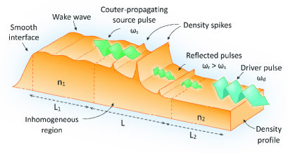
Fig. 1 illustrates the assumed tailored density profile composed of two homogeneous plasma slabs of density () and corresponding to plasma wavelengths of and and respective lengths and where . They are separated by a decreasing inhomogeneous region having a cosine square density profile, , which provides continuous density variation from to with the length ( for ) which approximately corresponds to three plasma wavelengths. To limit the effect of the vacuum heating DI1979 , a pre-plasma of length gradually rises from zero to at the left-side of vacuum-plasma interface.
The driver pulse is Gaussian linearly polarized along the direction with wavelength , longitudinal full width at half maximum (FWHM) and its amplitude is equal to (). Densities in the homogeneous regions give for the breaking condition , from Eq. 3, so that the generated wake wave is initially below the breaking level . The source pulse is rectangular and is polarized in the direction perpendicular to the driver polarization. Its length is equal to , and the amplitude is relatively low to not disturb the driven plasma wave.
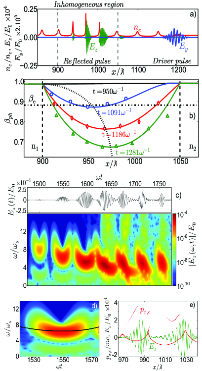
In Fig. 2a, the simulation results are presented. The driver pulse propagating in the positive direction initially generates a weakly nonlinear plasma wave. The wave only breaks in the inhomogeneous region. Density spikes develop in a finite time and constitute temporary existing mirrors. Since we know the breaking time (8), this process ensures spatial and temporal control of the breaking wave.
The source pulse is longer than the plasma wavelength, the reflection on the periodic train of density spikes generates a complex signal composed of several wave packets.
The time dependence of the wake wave phase velocity versus position in the inhomogeneity is shown in Fig. 2b for different times. The numerical results (shown by markers) appear in good agreement with the theoretically decreasing evolution of the phase velocity (solid lines) given by Eq (6). The breaking condition is at first satisfied at after the driver pulse has entered the target. The position of the minimal phase velocity progressively tends to the position of the maximal density gradient.
The time-frequency spectrum of the reflected radiation is presented in Fig. 2c where the electric field is plotted in the plane . The time-frequency analysis of is performed using the Gabor transformation defined as FS2002
| (9) |
where so that is the full length at half maximum of the Gaussian window.
A remarkable property of the high frequency radiation is the generation of a train of short electromagnetic wave packets. Space and time evolution of the mirror velocity, , leads to the generation of parabolic chirps as shown in Fig. 2d.
In order to calculate the frequency chirp we consider a plasma frequency, in the inhomogeneous region, of the form
| (10) |
with . From Eq. (6), the phase velocity can be locally approximated by
| (11) |
around the position of minimal phase velocity with . Using Eq. (4), we obtain for the frequency multiplication the following quadratic equation
| (12) |
where is the frequency multiplication after reflection on a mirror travelling at . Eq. (12) characterises the parabolic frequency modulation of the reflected pulses.
When electrons are injected into the wakefield, the mirrors decelerate due to momentum conservation which causes the wave packets to be down chirped. This phenomenon happens at the reflection from the fourth mirror formed behind the driver pulse as shown in Fig. 2e. Due to the decreasing mirror velocity , density maxima gradually increase offering higher reflectivity. The life spans of the mirrors are gradually prolonged. The average reflected frequency diminishes and the spectrum broadens according to Eq. (4).
The properties of the reflected pulse can be modified by changing the parameters of the inhomogeneous region: density profile, length and density variation .
In the spectral domain, average reflected frequency can be defined as
| (13) |
and the number of photons as
| (14) |
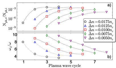
For density variation changing from to , the evolution of the reflected number of photons divided by the numbers of incident ones is shown in Fig. 3a as a function of the plasma wave cycle when reflection occurred. The average frequency, , is plotted in Fig. 3b. The length of the inhomogeneous region is equal to . We interpret the increase of the reflected photon number as the onset of the wave breaking. As predicted by Eq. (8), the larger is the density variation , the shorter the breaking time. For , the wave breaks at after the driver pulse has entered the inhomogeneity region, three wave periods behind the driver pulse. For , wave breaks during the first plasma wave cycle. For a given density, the frequency decreases while the number of reflected photons grows. Progressive decreasing of the phase velocity gives higher reflectivity but lower frequency up-shift (Eq. 4).
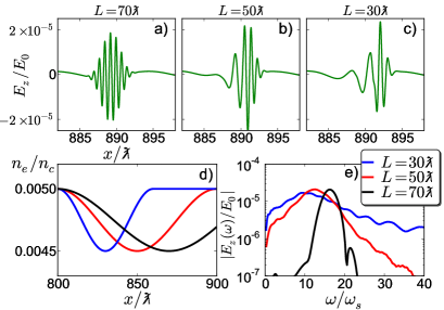
Now, we consider a localized density depression, as realized experimentally in Faure2010 , with a scale length shorter than the plasma wavelength . The density depression profile is composed of a first decreasing plasma region of length followed by a symmetric increasing one. As illustrated in Fig. 4d, the density varies from to a minimal value () for lengths , and . The normalized amplitude of the driver pulse is equal to whereas other parameters remain the same as previously described.
In the short-scale density perturbation, wave breaking leads to the generation of very short-lived mirrors. Reflected pulses have a very short duration ( for ), composed of a few cycles as displayed on Fig. 4a, b and c. Decreasing the depression length reduces the reflection time and generates shorter wave packets. For the density depression lengths (Fig. 4c) and (Fig. 4b), the density gradient is sufficiently abrupt to result in the acceleration of an electron bunch seen in the density profile as a narrow density spike. This is of interest for the electron injection scheme Bulanov1998 ; Brantov2008 ; Geddes2008 ; Chien1995 ; Suk2001 ; Faure2010 . In this case, a characteristic down chirping of the reflected light can be observed. The spectra of the reflected signals in Fig. 4e show that the frequency was multiplied by a factor of 16 for length . The shortening of the density depression length results in the generation of a stronger negative chirp.
In the downward density region, the plasma wave progressively travels with lower velocity than the reflected light. In the rising density part of the density depression, the plasma wave accelerates so that the distance to the reflected pulse can be reduced. In the simulations, the reflected pulse is not affected by the density modulation in the rising inhomogeneous density region.
In conclusion, a tailored downward plasma density offers time and space control for the generation of relativistic mirrors in a breaking laser-driven plasma wave. The reflected light properties including frequency multiplication, compression, chirping and duration can be modified by adjusting the density inhomogeneity parameters. This discovery is useful for experimental studies on the flying mirror concept, including compression of controllably chirped attosecond pulses with aperiodic soft and hard X-ray mirrors Beigman2002 . It makes a new step in the realization of a stable, coherent, compact and tunable high frequency light source required for various applications. The analysis of the reflection of the laser source on a density profile can also be contemplated as a plasma diagnostic tool.
One of the authors, M. L., acknowledges the Region Aquitaine for grant Aquitaine Cap Mobilité and expresses gratitude to P. Bolton and the Kansai Photon Science Institute for their generosity, their hospitality and their involvement in this project. The authors thank A. Ya. Faenov, T. A. Pikuz, Y. Hayashi, H. Kotaki and I. Daito for discussions.
References
- (1) G. A. Mourou et al., Rev. Mod. Phys. 78, 309 (2006).
- (2) F. Krausz and M. Ivanov, Rev. Mod. Phys. 81, 163 (2009).
- (3) R. Neutze, et al., Nature 406, 752 (2000).
- (4) M. Marklund and P. Shukla, Rev. Mod. Phys. 78, 591 (2006); Y. I. Salamin et al., Phys. Rep. 427, 41 (2006); S. V. Bulanov et al., Nucl. Instr. Meth. Phys. Res. A 660, 31 (2011); A. Di Piazza et al., Rev. Mod. Phys. 84, 1177 (2012).
- (5) S. V. Bulanov et al., Phys. Rev. Lett. 91, 085001 (2003).
- (6) S. S. Bulanov et al., Phys. Rev. E 73, 036408 (2006); S. S. Bulanov et al., Phys. Plasmas 19, 020702 (2012).
- (7) V. V. Kulagin et al., Phys. Plasmas 14, 113101 (2007); D. Habs et al., Appl. Phys.B 93, 349 (2008); A. G. Zhidkov et al., Phys. Rev. Lett. 103, 215003 (2009); H. Wu et al., ibid. 104, 234801 (2010); L. L. Ji et al., ibid. 105, 025001 (2010); S. S. Bulanov, et al., Phys. Lett. A 374, 476 (2010); S. V. Bulanov et al., Physics - Uspekhi (in press); M. Tamburini et al., arXiv:1208.0794v1 [physics.plasm-ph]; M. Wen et al., Appl. Phys. Lett. 101, 021102 (2012); H.-C. Wu and J. Meyer-ter-Vehn, Nat. Photonics 6, 304 (2012).
- (8) M. Kando et al., Phys. Rev. Lett. 99, 135001 (2007); M. Kando et al., ibid. 103, 235003 (2009).
- (9) T. Tajima and J. M. Dawson, Phys. Rev. Lett. 43, 267 (1979); E. Esarey et al., Rev. Mod. Phys. 81, 1229 (2009).
- (10) S. V. Bulanov et al., Phys. Fluids B 4, 1935 (1992).
- (11) J. M. Dawson, Phys. Rev. 113, 383 (1959).
- (12) S. V. Bulanov et al., Phys. Rev. E 58, R5257 (1998).
- (13) A. V. Brantov et al., Phys. Plasmas 15, 073111 (2008).
- (14) C. G. R. Geddes et al., Phys. Rev. Lett. 100, 215004 (2008); A. J. Gonsalves et al., Nat. Phys. 7, 862 (2011).
- (15) H. Suk et al., Phys. Rev. Lett. 86, 1011 (2001); P. Tomassini et al., Phys. Rev. ST Accel. Beams 6, 121301 (2003).
- (16) T. Y. Chien et al., Phys. Rev. Lett. 94, 115003 (1995).
- (17) K. Schmid et al, Phys. Rev. STAB 13, 091301 (2010).
- (18) J. Faure et al., Phys. Plasmas 17, 083107 (2010); P. Brijesh et al., ibid. 19, 063104 (2012); S. Fourmaux et al., Appl. Phys. Lett. 101, 111106 (2012).
- (19) A. I. Akhiezer and R. V. Polovin, JETP 3, 696 (1956).
- (20) A. Zhidkov et al., Phys. Plasmas 11, 5379 (2004).
- (21) T. Zh. Esirkepov et al, Phys. Rev. Lett. 103, 025002 (2009).
- (22) A. V. Panchenko et al., Phys. Rev. E 78, 056402 (2008).
- (23) V. F. D yachenko and V. S. Imshennik, Sov. J. Plasma Phys. 5, 413 (1979); F. Brunel, Phys. Rev. Lett. 59, 52 (1987).
- (24) H. G. Feichtinger and T. Strohmer, Advances in Gabor Analysis (Birkhauser, Boston, 2002).
- (25) J. Beigman et al., J. Opt. A 4, 433 (2002).