Laboratory limit on the charge of photons by electric field deflection
Abstract
The deflection of a laser beam traveling through a modulated electric field is measured using phase-sensitive detection to place an upper bound on photon charge. An upper limit of is obtained. The experiment involves a number of experimental techniques that are commonly encountered in modern precision measurements and is suitable for both advanced undergraduate and beginning graduate students in physical science as a laboratory exercise.
pacs:
14.70.BhI Introduction
Light is described as a stream of particles called photons, which propagate at the finite speed m/s. Unlike a stream of electrons, which are deflected under the influence of external fields, these photons, when traveling through a region of electric (or magnetic) field, have not been observed to deflect. Even more puzzling is that they are completely insensitive to the presence of the very fields that give rise to their own existence: the quanta of electromagnetic waves, though generated by accelerating electric charges, become indifferent to the same electric charges upon creation.
Essentially, photons are elementary bosonic particles with zero mass and zero charge. The former property—photons possessing no mass—underlies the fundamental interaction between two electric charges described by Coulomb’s inverse-square law. The fact that the inverse-square law holds with extreme precision, directly translates into validity of photons’ having zero mass, and vice-versa. Precision tests of the inverse-square law through Gauss’s law and its divergence theorem have been performed over the decades, and the best laboratory limitfaller of the mass of photons on the order of kg was obtained by Williams, Faller, and Hill in 1971.
The latter property—photons possessing no electric charge—is a bit trickier to imagine, simply because there is no complete theory that predicts otherwise. One possible scenario is that photons are single charged particles carrying the same magnitude of electric charge; however, the fact that electromagnetic fields themselves (made up of these same photons) have never been observed to be charged suggests that the single-charge photon model might be implausible, affirming that fields and charges are inherently different. Another scenario is to have photons with multiple charges (e.g. two types of photon with opposite signs of charge or three different types including a neutral one), thereby obeying overall charge neutrality. This is essentially to conjecture a non-Abelian gauge theory in which a nontrivial multiplet of interacting bosons exists. The problem with this scenario is that the charge of the photon must be quantized in units of the elementary electric charge, but the observed photon charge is many orders of magnitude smaller than . The extra degeneracy associated with the photons therefore appears to contradict the totality of data in the Standard Model, as pointed out by Okunokun1 ; okun2 .
The quest to understand the ultimate nature of photon goes back to 1932 when de Broglie proposed that a photon is composed of a neutrino and an antineutrino, satisfying the spin-1, zero-mass, and zero-charge characteristics of the photon.deb In this model, photons are composite particles—rather than elementary particles—described as a bound state formed by a pair of neutrinos obeying Fermi-Dirac statistics (i.e. photons are fermions). The neutrino theory of photons was further developed by W. A. Perkinsneutrino in 1967, but the work generated little interest and no dedicated experimental activity has been performed to fully reveal the photon’s true nature. Obviously, the mere absence of a complete theoretical framework is no reason not to undertake precision tests on the fundamental properties of photons, primarily because such tests are not only crucial to our basic understanding of electromagnetic theory, but also they provide a valuable opportunity to assess how well the existing theory has been experimentally tested, particularly in a laboratory setting.rev
| Authors | Year | Interaction source | Photon source | |
|---|---|---|---|---|
| Grodzins et al.grod | 1961 | Electric field | Decay of Fe57 (laboratory test) | |
| Stover et al.stover | 1967 | Electric field | Laser (laboratory test) | |
| Present work | 2012 | Electric field | Laser (laboratory test) | |
| Cocconicocconi | 1992 | Magnetic field | Extragalactic radiation | |
| Cocconi & Raffeltcocconi2 ; raffelt | 1994 | Magnetic field | Radio pulsars | |
| Sivaramsivaram3 | 1994 | Charge asymmetry | CMB | |
| Semertzidis et al.lazarus | 2003 | Magnetic field | Laser (laboratory test) | |
| Kobychev and Popovpopov | 2005 | & | Magnetic field | Extragalactic radiation |
| Caprini and Ferreiracaprini | 2005 | Charge asymmetry | CMB | |
| Altschulaltschul | 2007 | & | Magnetic field | Extragalactic radiation |
| Sivaram and Arunsivaram | 2010 | Magnetic field | Hawking radiation from a black hole |
According to the 2012 Particle Data Group (PDG)pdg , the best limit on the charge of a photon has been obtained by looking for Aharonov-Bohm phase differences from extragalactic radiation.altschul The non-observation of such phase differences has placed an upper bound on the photon charge at the level of , assuming all photons have the same charge. Several other limits based upon similar astrophysical observations have been reported since 1988. Examples include: limits derived from the analysis of the energy spreads of incoming photons from both radio pulsars cocconi2 ; raffelt and extragalactic sources cocconi ; popov , and the cosmic microwave background (CMB) sivaram3 ; caprini (See Table 1 for a summary of the current status on the bounds of the photon charge). In contrast, only two laboratory limits—using an electric field as a source of interaction—exist in the literature, one by Grodzins et al.grod in 1961 and the other one by Stover et al.stover in 1967. In fact, the photon charge limit reported by Stover and his coworkers was the by-product of an experiment originally intended at searching for an electron-proton charge inequality. Additionally, the naive procedure to place a limit by calculating a total change of the electric charge on a spheroid per unit photon has been cast into serious doubt.altschul2 From this perspective, the experiments by Grodzins et al. remains the only laboratory experiment solely dedicated to testing on the charge of a photon involving electric fields, although the work has not been published in a peer-reviewed journal.
Here, we report an experimental test placing an upper limit on the charge of a photon using a light beam traveling through an electric field with a phase-sensitive detection technique. Our experimental arrangement is distinct from previous tests constraining limits on the photon charge for several reasons: (i) We employ electric, rather than magnetic deflection; all previous reports have exclusively employed deflection by magnetic fields, either from astrophysical data cocconi ; raffelt ; popov ; altschul or using an electrically tunable magnet lazarus . (ii) Our simple experimental scheme can be readily implemented in undergraduate laboratories, introducing students to a number of experimental techniques that are commonly employed in modern precision measurements. These include: phase-sensitive detection, precision capacitance measurements, Michelson interferometry, and phase-delay measurements. (iii) With some modifications to the present setup, one could place a stronger limit on the photon charge by at least two orders of magnitude; any modest improvement to the current limit should be regarded as a valuable contribution to the field, particularly when the limit is obtained from a laboratory test in which all the relevant parameters are controlled.
II Experimental apparatus
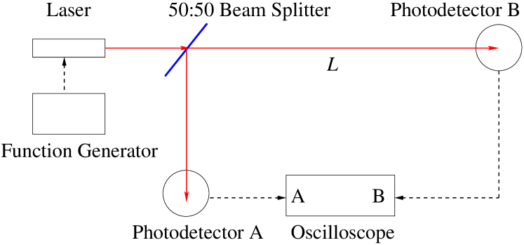
The experimental configuration is depicted in Fig. 1. A laser beam of nm travels through a circular parallel-plates capacitor whose diameter is cm. The signal from a function generator (Agilent 33120A) is amplified by a high voltage power supply ( V) which then modulates the voltage across the parallel-plate. The signal from the function generator also provides a reference input for a lock-in amplifier (Stanford Research 830), and the resulting “deflection” signal from a position sensitive photodiode is demodulated by the lock-in. Not shown in Fig. 1 is an additional mirror employed to reflect the beam, which is made to travel 50 m down a hallway and back, making a total leveraging distance of m. The angular deflection is then expressed as , where is the signal representing the horizontal displacement of the quadrant photodiode.
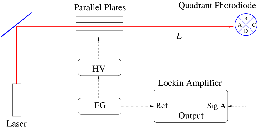
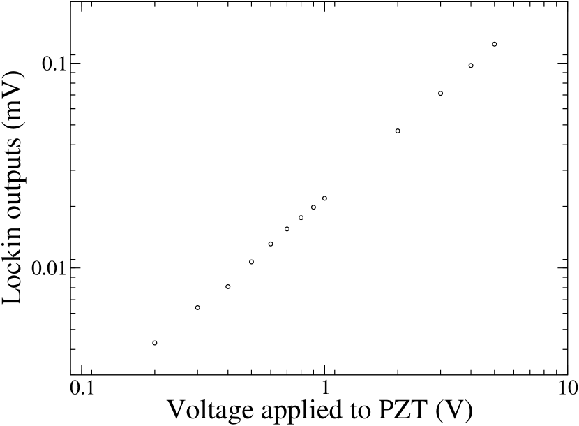
The angular resolution (i. e. minimum detectable signal ) is determined in the following way: A piezoelectric transducer (PZT) is attached to a linear stage, which then physically moves the photo detector back and forth at a modulation frequency (i.e. it mimics deflections). The output of the lock-in amplifier is plotted as a function of the modulation voltage applied to the PZT, as shown in Fig. 2. The lock-in response is linear, and its sensitivity can be inferred from the smallest PZT voltage modulation it is able to detect, which is measured to be =103 mV. Note that corresponds to a certain distance that the PZT travels (i .e. ).
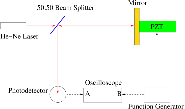
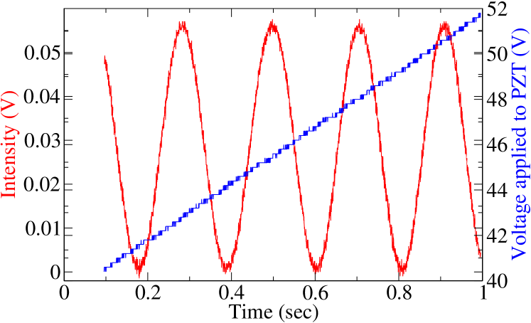
Next, we calibrate the voltage applied to the PZT with the actual distance traveled by it. This is achieved by implementing a Michelson’s interferometer, as shown in Fig. 3. The period of interference intensity is related to , where is the wavelength of a Helium-Neon laser. From this, the PZT distance-to-voltage ratio () is measured to be nm/V. This yields a deflection sensitivity of nm and thus an angular sensitivity of radians.
Another important parameter to be characterized is the absolute separation distance of the parallel-plates. This is most effectively achieved by measuring the capacitance at different gap separations, which is expected to obey the power law for parallel-plate geometry through , where is the permittivity constant in vacuum and is the plate area.
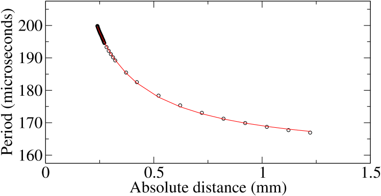
In Fig. 4, a circuit diagram of a simple relaxation oscillator is presented along with the measurement data in which the oscillation period is plotted against the separation distance. At the heart of the relaxation oscillator is an op-amp (OP27) which acts as a comparator; its oscillation period is proportional to the unknown capacitance and is expressed as , where M and is the total capacitance including the 47 pF capacitor.
The purpose of the capacitance measurements is two-fold: First, it enables the extraction of a point of contact from which the absolute distance is determined from a relative displacement . Second, more importantly, it identifies a distance range in which the parallel-plate formula is validated. At a short separation distance (i.e. mm), the data tends to suffer from a severe deviation from the expected power law. Because of finite-parallelism, our measurements have been applied to a distance range from 1.5 mm to 0.25 mm, and a separation distance of =1.3 mm is maintained throughout the experiment. The relaxation oscillator is quite useful in its own right and could be applied in another independent project run by students. For instance, various power laws governing the capacitance versus distance in different geometries could be studied, as they have raised a series of discussions in recent Casimir force measurements.ana ; cas

III Results and analysis
Based upon elementary considerations of a relativistic, massless particle whose charge experiences an electrostatic force inside a parallel-plate, the photon’s deviation from its straight path is given by
| (1) |
where is the photon energy with , Planck’s constant. is the effective interaction length corresponding to the diameter of the plates employed in our experiment. The above expression can be also related to the previous experiments constraining the charge of the photon by magnetic deflection in which the angular deflection on the detector is expressed as:
| (2) |
The first term in the brackets is the feature of an experiment in which the field strength is modulated. If no modulation on the field strength is applied (i.e. ), one is left with the second term which represents the angular spread of the incoming photons, within a bandwidth . Assuming no modulation and replacing the field magnitude , the upper limit on the charge of the photon becomes
| (3) |
Aside from the absence of a factor of two arising from a binomial expansion, Eq. (3) exactly matches the derived resultscocconi ; altschul for the case of the deflection of a photon that has traveled a distance through the intergalactic magnetic field . Note that less energetic photons and larger bandwidths are needed to constrain a stronger limit, as was applied in the previous experiments.
It is clear from Eq. (2) that unless , a greater sensitivity is achieved by modulating the strength of an external field, leading to the upper limit on the photon charge:
| (4) |
Replacing the modulation of the electric field with that of a magnetic field , one also retrieves the upper limit of the photon charge obtained by Semertzidis et al.lazarus , which was reported to be . It should be noted that the charge limit obtained in all experiments involving magnetic deflection assume the cyclotron trajectory of the photon in a transverse magnetic field. There, the linear momentum of the photon is conserved in a Larmor radius given by , where is the relativistic momentum of the photon, is the oscillation frequency of the photon; because magnetic forces do no work, the photon energy is independent of its mass and its momentum remains constant, given by .
The situation is somewhat different in the case of the electric field deflection. Because the linear momentum associated with the direction of the applied electric field (i.e. the direction in which the photon is deflected) is not conserved when it travels through the electric field, the photon gains electric potential energy. In fact, the gain of energy of photons crossing an electric field can be directly measured by determining the absorption condition of resonance in the decay of, for example, Fe57 based upon the Mössbauer effectgrod —the underlying technique in the earliest experiment aimed to measure the charge of a photon.
We now place an upper limit on the charge of the photon in our experimental situation. Using the angular resolution radians and the separation distance 1.3 mm, we attain
| (5) |
which is remarkable given the relatively straightforward approach adopted in an undergraduate laboratory. This is only two orders of magnitude weaker than the most stringent limit obtained from a laboratory test involving magnetic deflectionlazarus . Clearly, one can easily notice an advantage in employing magnetic deflection with the speed of light as a multiplication factor in the field strength (i. e ). However, a parallel-plate is easy to implement and requires only a modest amplification of the applied voltage for placing a strong limit. In principle, it is possible to improve the present limit by at least two orders of magnitude; this is achieved in part by increasing both the modulation voltage to about 2 kV (before the electric field breakdown in air) and the interaction length to about cm.
One can argue that Rayleigh scattering between photons and air molecules should be taken into account. Note that our phase-sensitive detection is only sensitive to the modulation frequency, and no “deflection” was registered at the output of the lock-in amplifier. This suggests that in the presence of any systematic effects leading to spurious “deflections” the quoted sensitivity corresponds to the maximum charge of the photon (i.e. the actual charge of the photon could be much smaller).
We have also independently measured the speed of light of the employed beam to investigate any possible effects caused by the dielectric permittivity in air. This was performed by modulating the intensity of the light beam at tens of MHz and measuring the phase difference originating from a time delay over a certain distance (see Fig. 5).
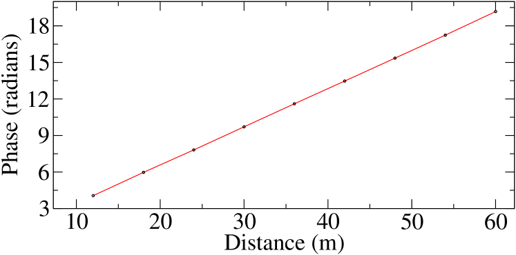
The measured value agrees with the accepted, and no difference was observed from the speed of light in vacuum within our experimental uncertainties.
IV Conclusion
We have reported the result of an experimental test placing a limit on the photon charge by deflection in an electric field. An upper bound on the order of has been obtained note . Our relatively straightforward arrangement can be easily implemented in an undergraduate laboratory in which students gain exposure to a variety of experimental techniques. The entire experiment— including all the calibrations involving a Michelson’s interferometer, the construction of a relaxation oscillator, and the speed of light measurements—could be completed in a period of several weeks by one or two advanced undergraduate students. Furthermore, the present limit is only two orders of magnitude away from the best laboratory limit reported to date. With some modification to the present setup, one could achieve a tighter upper bound, thereby providing a valuable contribution to ongoing searches for the electric charge of the photon.
Acknowledgements.
We thank Roberto Onofrio, Paul Fontana, and Michael Morgan for providing valuable comments on our manuscript, and Jeff Wilhite for machining various parts for our experiment. This work is supported by the M. J. Murdock Charitable Trust and by Research Corporation through Single Investigator Cottrell College Science Award (SI-CCSA). A. Hankins acknowledges the research support made possible by Pat and Mary Welch.References
- (1) Williams, Faller, and Hill, “New experimental test of Coulomb’s law: A laboratory upper limit on the photon rest mass,” Phys. Rev. Lett. 26, 721 (1971).
- (2) L. B. Okun,“On the charge of the photon,” arXiv:hep-ph/0505250v1 (2005).
- (3) L. B. Okun,“Photon: history, mass, charge,” arXiv:hep-ph/0602036v2 (2006).
- (4) L. de Broglie, Compt. Rend. 195, 536, 862 (1932).
- (5) W. A. Perkins, “Neutrino theory of photons,” Phys. Rev. 137, B1291 (1967).
- (6) A. L. Akhiezer and M. P. Rekalo, “Electric charge of elementary particles,” Sov. Phys. -Usp. 17, 864 (1975).
- (7) J. Beringer et al., “Review of particle physics,” Phys. Rev. D 86, 010001 (2012).
- (8) B. Altschul,“Bound on the photon charge from the phase coherence of extragalactic radiation,” Phys. Rev. Lett. 98, 261801 (2007).
- (9) G. Cocconi, “Upper limit for the electric charge of the photons from the millisecond pulsar 1937+21 observations,” Phys. Lett. B 206, 705 (1988).
- (10) G. Raffelt,“Pulsar bound on the photon electric charge reexamined,” Phys. Rev. D 50, 7729 (1994).
- (11) G. Cocconi,“Upper limits on the electric charge of the photon,” Am. J. Phys. 60, 750 (1992).
- (12) V. V. Kobychev and S. B. Popov, “Constraints on the photon charge from observations of extragalactic sources,” Astro. Lett. 31, 149 (2005).
- (13) C. Sivaram, “Upper limit on the photon electric charge from the cosmic microwave background,” Am. J. Phys. 63, 473 (1995).
- (14) C. Caprini and P. G. Ferreira, “Constraints on the electrical charge asymmetry of the universe,” J. Cosmol. Astropart. Phys. 02 (2005) 006.
- (15) L. Grodzins, D. Engelberg, and W. Bertozzi, Bull. Am. Phys. Soc. 6, 63 (1961).
- (16) R. W. Stover, T. I. Moran, and J. W. Trischka, “Search for an electron-proton charge inequality by charge measurements on an isolated macroscopic body,” Phys. Rev. 164, 1599 (1967).
- (17) Y. K. Semertzidis, G. T. Danby, and D. M. Lazarus,“New laboratory technique for measuring the photon charge,” Phys. Rev. D 67, 017701 (2003).
- (18) B. Altschul, “Astrophysical bounds on the photon charge and magnetic moment,” Astropart. Phys 29, 290 (2009).
- (19) C. Sivaram and K. Arun, “Bounds on photon charge from evaporation of massive black holes,” arXiv:1003.3818v1 (2010).
- (20) W. J. Kim and U. D. Schwarz, “Potential contributions of noncontact atomic force microscopy for the future Casimir force measurements,” J. Vac. Sci. Tech B 28, C4A1 (2010).
- (21) T. Graveson, C. Rackson, and W. J. Kim, “Development of a high-sensitivity torsion balance to investigate the thermal Casimir force,” Int. J. Mod. Physics: Conf. Ser. 14, 337 (2012).
- (22) W. J. Kim, M. Brown-Hayes, D. A. R. Dalvit, J. H. Brownell and R. Onofrio, “Anomalies in electrostatic calibration for the masurements of the Casimir force in a sphere-plane geometry,” Phys. Rev. A 78, 020101(R) (2008).
- (23) E. D. Greaves et al., “A one-way speed of light experiment,” Am. J. Phys. 77, 894 (2009).
- (24) In some sense, our result based on electric deflection is the first of its kind and arguably the only direct, laboratory test available in the literature. As briefly discussed, the charge limit obtained by Stover et al is secondary, and its result is rather problematic, while the earliest work by Grodzins et al. has never been published in a journal and only the result is available on a review articlerev written four decades ago.