Non-perturbative Interband Response of InSb
Driven Off-resonantly by Few-cycle Electromagnetic Transients
Abstract
Intense multi-THz pulses are used to study the coherent nonlinear response of bulk InSb by means of field-resolved four-wave mixing spectroscopy. At amplitudes above 5 MV/cm the signals show a clear temporal substructure which is unexpected in perturbative nonlinear optics. Simulations based on a two-level quantum system demonstrate that in spite of the strongly off-resonant character of the excitation the high-field pulses drive the interband resonances into a non-perturbative regime of Rabi flopping.
pacs:
42.65.Re, 78.47.nj, 42.65.-kSemiconductors form a uniquely well-defined laboratory to explore novel limits of nonlinear optics. A key parameter for interaction of a coherent light field with an electronic transition is given by the Rabi frequency . is the electric field strength and the transition dipole moment. When the dephasing rate is negligible compared to , coherent Rabi flopping governs the dynamics of electronic systems Cohen-Tannoudji et al. (1977). If the detuning of the driving electromagnetic field is smaller than the response of a system cannot be described by the perturbative approach which usually depicts off-resonant nonlinear optics. This non-perturbative excitation regime provides access to many fascinating quantum effects in semiconductors such as Rabi splitting, self-induced transparency and generation of high harmonics Wegener et al. (1990); Cundiff et al. (1994); Giessen et al. (1998); Schülzgen et al. (1999); Mücke et al. (2001); Carter et al. (2005); Choi et al. (2010). In particular, sufficiently intense and ultrashort laser pulses have been exploited to implement ultimate scenarios in which the duration of the light pulse, the Rabi cycle and the oscillation period of the carrier wave all become comparable in size Tritschler et al. (2003a). Under such conditions, a detailed insight into the nonlinear optical interaction calls for complete phase and amplitude resolution of all interacting light fields. However, in most of the cases, the lack of phase-stable laser pulses and fast detectors does not allow for capturing sub-cycle polarization dynamics of a system.
The development of ultraintense THz laser systems generating phase-stable transients with field amplitudes above 1 MV/cm Reimann et al. (2003); Hebling et al. (2008); Hirori et al. (2011) paves the way towards a coherent spectroscopy of extreme nonlinearities in condensed matter systems with absolute sampling of amplitude and phase. Recent experiments performed with high-field multi-THz pulses have demonstrated a high potential of this approach Luo et al. (2004); Kuehn et al. (2009); Leinß et al. (2008); Kuehn et al. (2011). However, the regime of an off-resonant excitation of Rabi flopping has remained almost unexplored due to the lack of sufficiently intense and phase-locked pulses. The latest breakthrough in generation and field-resolved detection of multi-THz pulses with peak fields up to 100 MV/cm Sell et al. (2008); Junginger et al. (2010) opens up the possibility to explore this highly non-perturbative regime.
In this Letter, we report the nonlinear response of the bulk semiconductor indium antimonide (InSb) excited far below interband resonance using our novel high-field multi-THz laser source Junginger et al. (2010): Time-resolved four-wave mixing (FWM) signals are recorded with amplitude and phase at different THz peak fields of the excitation pulses. For the highest intensities, the Rabi frequency becomes comparable to the detuning and the interband resonance is driven into a non-perturbative regime of Rabi flopping. Our simulations of the FWM response based on the Maxwell-Bloch equations provide a qualitative understanding of the phenomena observed experimentally.
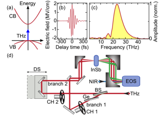
The sample under study is a (100)-oriented undoped single crystal of InSb (Fig. 1(a)) mechanically polished to a thickness of 30 m and kept at room temperature. THz transients with a center frequency of THz, a bandwidth of 8 THz (full width at half maximum, FWHM) and variable peak fields between 2 MV/cm and 5.3 MV/cm are generated by difference frequency mixing of near-infrared pulse trains with a repetition rate of 1 kHz in gallium selenide (GaSe) emitters (Figs. 1(b) and 1(c)) Junginger et al. (2010). A specific feature of our experiment is a large detuning of 18 THz between the THz transients and the nearest interband resonance of InSb (E THz). Thus, the entire THz spectrum is located well below the band gap excluding the possibility of direct linear excitation of electron-hole pairs.
We use a two-dimensional scheme of nonlinear spectroscopy (Fig. 1(d)). In order to perform a THz multi-wave mixing experiment, a pair of mutually synchronized pulses is obtained by splitting the THz beam after the GaSe emitter crystal. In this way nonlinear mixing effects of two pulses within the emitter itself are precluded. A germanium (Ge) beam splitter set at Brewster’s angle and coated with a 6-nm-thick gold layer provides a splitting ratio of 1:1. The transmitted electric field in branch 2 () is delayed by a retroreflector stage. The transient in branch 1 () propagates through a second Ge wafer to match the dispersion of . The THz beams in both branches are individually chopped with frequencies of 500 Hz and 250 Hz, respectively, and the chopper phases are locked to the 1 kHz pulse train. This configuration enables a fast and efficient acquisition of the transmitted signals from only branch 1, only branch 2 or both branches at the same time (). The THz beams are tightly focused onto the same spot on the sample (FWHM: 85 m). The emerging linear and nonlinear fields are collected with large numerical aperture and directed onto a 140-m-thick GaSe electro-optic sensor gated by near-infrared pulses with a duration of 8 fs.
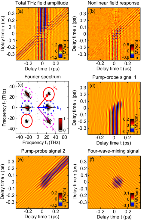
Fig. 2(a) shows the total transmitted field as a function of the electro-optic sampling delay time and the relative temporal offset between the THz pulses. The signal from branch 1 with a fixed temporal position appears as a set of vertical lines of constant phase centered around ps, whereas the diagonal lines correspond to the delayed signal from branch 2. The external peak fields are 2 MV/cm per pulse. The field strengths within InSb are attenuated by a Fresnel factor defined by a refractive index of in the frequency range of interest Adachi (1987). The nonlinear signal shown in Fig. 2(b) is retrieved by subtracting the contributions of individual transients and from the total response : . The Fourier transform of (Fig. 2(c)) has a direct correspondence with the wave vector space and, thus, allows to disentangle different contributions to the total nonlinear field response Kuehn et al. (2009). The inverse Fourier transform of selected regions in frequency space depicted in Fig. 2(c) provides the temporal fingerprints of multi-wave mixing signals of various orders. The pump-probe signals for each THz pulse, located around wave vectors (, ) and (, ) (Fig. 2(c)), are shown in Figs. 2(d) and 2(e), respectively. These signals correspond to the transmission change of the sample excited by the first and probed by the second THz transient. They do not depend on the relative phase.
Most remarkably, a FWM signal at the wave vector (, ) becomes clearly discernible (Fig. 2(c)). This signal features lines of constant phase that point along a downward diagonal (Fig. 2(f)) indicating its dependence on the respective phases of both THz transients. Thus, it bears information about coherence induced in the sample. Therefore, we will concentrate in the following on the FWM signal which is free from influence of incoherent excitation processes dominating the pump-probe response such as two-photon absorption Olszak et al. (2010) or impact ionization Hoffmann et al. (2009).
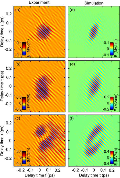
To study the field dependence of the FWM signal, external peak fields of 2 MV/cm, 3.5 MV/cm and 5.3 MV/cm per pulse are selected. The corresponding pulse intensities are , and where GW/cm2. For the lowest peak electric field we observe an oval-shaped envelope of the FWM signal, identical to the cross-correlation function of both pulses (Fig. 3(a)). This result is as expected in the limit of perturbative nonlinear optics far from resonance. In contrast, increasing the field strength up to 3.5 MV/cm leads to a deviation from the symmetric profile resulting in an S-shaped signal (Fig. 3(b)). Surprisingly, the maximum field of 5.3 MV/cm leads to a splitting of the FWM signal (Fig. 3(c)). A minimum appears in the temporal region where the strongest total excitation field is present. This signature is an unequivocal indication of an extremely nonlinear interaction.
Our experimental results may be understood by using a simplified model of a two-level system representing the interband resonance in InSb. The simulation is based on the Maxwell-Bloch equations Ziolkowski et al. (1995) which are solved numerically without applying the slowly-varying-envelope and rotating-wave approximations. The solution is obtained by an iterative predictor-corrector finite element method. For the simulations we assume a dephasing time of ps Andrews and Sen (1998) and a depopulation time of ps. Owing to the extremely short THz transients the choice of the relaxation time barely affects the results of the simulations as long as and are longer than the duration of the THz pulse. The transition dipole moment eÅ and the density of the two-level systems cm-3 were adjusted in order to provide the best agreement with the shapes and intensities of the FWM signals measured experimentally.
Figs. 3(d)-(f) show the time domain FWM signals simulated for the same peak fields as those used for the experimental results depicted in the panels on the left. For the simulation we assume Fourier-limited Gaussian THz transients with a FWHM duration set to the pulse width measured experimentally. A perturbative response at moderate field strengths leads to an oval envelope of the FWM signal (Fig. 3(d)). At the intermediate THz intensity this envelope evolves into an S-shape (Fig. 3(e)). Finally, external peak fields above 5 MV/cm induce a minimum in the center of the signal, where the total field is strongest. This results in two side-lobes similar to those observed in the experiment (see Figs. 3(c) and 3(f)). As one can clearly see, the simulations with a single energy electronic resonance allow us to reproduce the essential features observed in the experiment. This result is highly surprising since it is well known that interband excitations in bulk semiconductors like InSb include a continuum of electronic resonances with a broad distribution of frequencies above the absorption edge. Nevertheless, simulations using a set of two-level systems with a density distribution fitting the joint density of states in InSb essentially lead to the same results as those shown in Figs. 3(c) and 3(f). The reason for that is the steep dependence of the non-perturbative response on the detuning frequency. This finding is supported by the density of the two-level systems estimated from our simulations which constitutes only about 1% of the total number of available states in the conduction band of InSb. These are the states near the band edges which constitute the interband transitions with the smallest detuning.
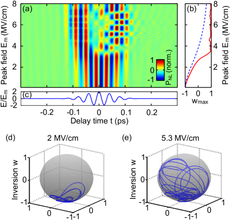
A qualitative physical understanding of the splitting observed in the FWM signal can be obtained by considering the polarization response of a two-level system driven by two THz transients with zero delay time ( ps). Fig. 4(a) depicts the simulated time-resolved polarization at the frequency of the driving pulses for different peak electric fields . In case of moderate fields the maximum population inversion shown in Fig. 4(b) remains negative and the deflection of the Bloch vector from the ground state is minor as illustrated in Fig. 4(d). Therefore, the response of the two-level system is perturbative and the shape of the polarization signal (Fig. 4(a)) follows the profile of the driving fields shown in Fig. 4(c). The FWM signal, thus, can be described in terms of an instantaneous third-order nonlinearity. However, this picture breaks down as soon as field amplitudes exceed 3 MV/cm and a clear splitting of the temporal signature of the FWM signal starts to develop. In this case the maximum population inversion shown by the solid red line in Fig. 4(b) becomes positive (), indicating the onset of a strongly non-perturbative regime. As illustrated in Fig. 4(e), a THz peak field of 5.3 MV/cm promotes the system almost to the limit of complete population inversion. This surprising result radically differs from the case of an off-resonant excitation by a continuous wave where the complete population inversion can be achieved only in the limit of infinitely high electric fields (see the dashed blue line in Fig. 4(e)). This fact indicates a clear violation of the slowly-varying-envelope approximation for our conditions. Finally, in the center of the FWM signal, where the driving electric field reaches its maximum, the polarization oscillates mainly at high harmonic frequencies Tritschler et al. (2003b). The response at the fundamental frequency becomes weak leading to the observed minimum (Fig. 4(a)). This regime of a non-perturbative excitation sets in when the maximum Rabi frequency becomes comparable to the large detuning of 18 THz at MV/cm.
In conclusion, we have studied the off-resonant FWM response of bulk InSb which provides a direct access to the coherent dynamics of the interband polarization response at THz frequencies. The observed splitting of the FWM signals for electric fields above 5 MV/cm manifest the onset of a non-perturbative response of Rabi flopping. This extremely nonlinear behavior underpins the high potential of the novel high-field multi-THz technology for high harmonics generation Golde et al. (2008) and coherent control of quantum states in semiconductors Leinß et al. (2008); Cole et al. (2001). The high fields and excellent signal-to-noise performance of THz multi-wave mixing open a way for investigations of the coherent response in a large variety of important resonances in complex systems such as intermolecular librations in hydrogen-bonded liquids or energy gaps in superconducting condensates.
References
- Cohen-Tannoudji et al. (1977) C. Cohen-Tannoudji et al., Quantum Mechanics (Wiley, New York, 1977).
- Wegener et al. (1990) M. Wegener et al., Phys. Rev. A 42, 5675 (1990).
- Cundiff et al. (1994) S. T. Cundiff et al., Phys. Rev. Lett. 73, 1178 (1994).
- Giessen et al. (1998) H. Giessen et al., Phys. Rev. Lett. 81, 4260 (1998).
- Schülzgen et al. (1999) A. Schülzgen et al., Phys. Rev. Lett. 82, 2346 (1999).
- Mücke et al. (2001) O. D. Mücke et al., Phys. Rev. Lett. 87, 057401 (2001).
- Carter et al. (2005) S. Carter et al., Science 310, 651 (2005).
- Choi et al. (2010) H. Choi et al., Nature Photon. 4, 706 (2010).
- Tritschler et al. (2003a) T. Tritschler et al., Phys. Rev. Lett. 90, 217404 (2003a).
- Reimann et al. (2003) K. Reimann et al., Opt. Lett. 28, 471 (2003).
- Hebling et al. (2008) J. Hebling et al., J. Opt. Soc. Am. B 25, B6 (2008).
- Hirori et al. (2011) H. Hirori et al., Appl. Phys. Lett. 98, 091106 (2011).
- Luo et al. (2004) C. W. Luo et al., Phys. Rev. Lett. 92, 047402 (2004).
- Kuehn et al. (2009) W. Kuehn et al., J. Chem. Phys. 130, 164503 (2009).
- Leinß et al. (2008) S. Leinß et al., Phys. Rev. Lett. 101, 246401 (2008).
- Kuehn et al. (2011) W. Kuehn et al., Phys. Rev. Lett. 107, 067401 (2011).
- Sell et al. (2008) A. Sell et al., Opt. Lett. 33, 2767 (2008).
- Junginger et al. (2010) F. Junginger et al., Opt. Lett. 35, 2645 (2010).
- Adachi (1987) S. Adachi, Phys. Rev. B 35, 7454 (1987).
- Olszak et al. (2010) P. D. Olszak et al., Phys. Rev. B 82, 235207 (2010).
- Hoffmann et al. (2009) M. C. Hoffmann et al., Phys. Rev. B 79, 161201 (2009).
- Ziolkowski et al. (1995) R. W. Ziolkowski et al., Phys. Rev. A 52, 3082 (1995).
- Andrews and Sen (1998) J. T. Andrews and P. Sen, Quantum Semiclass. Opt. 10, 663 (1998).
- Tritschler et al. (2003b) T. Tritschler et al., Phys. Rev. A 68, 033404 (2003b).
- Golde et al. (2008) D. Golde et al., Phys. Rev. B 77, 075330 (2008).
- Cole et al. (2001) B. E. Cole et al., Nature 410, 60 (2001).