Pulse-gated quantum dot hybrid qubit
Abstract
A quantum dot hybrid qubit formed from three electrons in a double quantum dot has the potential for great speed, due to presence of level crossings where the qubit becomes charge-like. Here, we show how to take full advantage of the level crossings in a pulsed gating scheme, which decomposes the spin qubit into a series of charge transitions. We develop one and two-qubit dc quantum gates that are simpler than the previously proposed ac gates. We obtain closed form solutions for the control sequences and show that these sub-nanosecond gates can achieve high fidelities.
pacs:
03.67.Lx,73.21.La,85.35.Be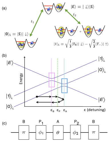
A key figure of merit for a quantum information processing device is the ratio of the quantum coherence time to the time required to perform qubit gate manipulations DiVincenzo (1995); Preskill (1998); Fisher (2003). The recently proposed hybrid quantum dot qubit Shi et al. (2012) is a relatively simple qubit architecture that could achieve a higher figure of merit than previous qubit designs Koppens et al. (2006); Levy (2002); DiVincenzo et al. (2000). The qubit itself is a set of two states with total spin quantum numbers and , with the two different states using the singlet and triplet in a doubly-occupied dot and a single spin in a singly-occupied dot. The two states of the qubit have different energies, and Ref. Shi et al., 2012 proposes to implement gate operations using high-frequency (1040) resonant RF pulses. This method is feasible Martinis et al. (2002); Pioro-Ladrière et al. (2008), but it is significantly more complicated to implement experimentally than the pulse-gating methods used for charge qubits in Refs. Hayashi et al., 2003; Gorman et al., 2005; Petta et al., 2006; Shinkai et al., 2009; Petersson et al., 2010 and for spin qubits in Refs. Petta et al., 2005; Laird et al., 2010; Gaudreau et al., 2011; Shulman et al., 2012; Maune et al., 2012. Here we show how to implement pulse-gating of the quantum dot hybrid qubit. One- and two-qubit gates require a modest number of non-adiabatic voltage pulses (five and eight, respectively), each of which is similar to those already used for gate operations on charge qubits and singlet-triplet spin quits.
The two logical qubit states of the hybrid quantum dot qubit are and , where , , and are two-particle singlet (S) and triplet (T) states in the left dot, and and respectively denote a spin-up and spin-down electron in the right dot. These states form a decoherence-free subspace that is insensitive to long-wavelength magnetic flux noise; moreover, decoherence processes that do not explicitly couple to spin or induce a transition of an electron to the reservoir do not induce transitions that go outside of the subspace of an individual qubit Lidar et al. (1998). The qubit has the same symmetries in spin space as the triple-dot qubit proposed by DiVincenzo et al. DiVincenzo et al. (2000), but is simpler to fabricate because it requires a double dot instead of a triple dot. Transitions between the logical qubit states and are allowed when tunneling is introduced between the dots. The physical process that leads to transitions between the two logical qubit states and involves an intermediate state that has one electron in the left dot and two electrons in the right dot, and the same total and . Fig. 1(a) is a schematic of the hybrid qubit and of a physical process that yields transitions between the logical states and . In the figure the doubly occupied right dot is labeled as having a singlet ground state, but the energy level diagram applies for both positive and negative singlet-triplet energy splittings in the right dot, and the spin of the lower energy state is not essential for the discussion below. We assume that the singlet-triplet splitting in the right dot is large enough that higher energy states of the right dot do not mix appreciably with the states that we consider explicitly here.
Rabi oscillations between two quantum states and are achieved by changing the detuning suddenly to a value at which the energy difference between the states is smaller than the coupling between them. Very near the avoided crossing between two states, the time evolution is prescribed by the two-state Hamiltonian
| (1) |
where is the coupling between the two states and and is the energy difference between the two states in the absence of coupling. Significant mixing between the states occurs only when . If one pulses the system suddenly to , so that the state at time is , then the time evolution of the two-state system is given by , which oscillates between and at the Rabi frequency . A pulse of duration rotates the state on the Bloch sphere by an angle around the -axis Nielsen and Chuang (2000).
Fig. 1(b) shows the energies of the states , , and as a function of detuning. The energy difference between and , which is the singlet-triplet energy splitting in the left dot, typically is substantial (of order meV, corresponding to a frequency 25 GHz) and depends only moderately on the detuning Shi et al. (2011), so achieving an avoided crossing of and is typically not feasible. Therefore, pulse-gating is ineffective in inducing transitions directly between the two qubit states. However, there is a value of the detuning at which there is an avoided crossing between the states and , and another value of the detuning at which there is an avoided crossing between the states and . Transitions from to can be induced by first pulsing to , the avoided crossing between and , and then pulsing to , the avoided crossing between and . Similarly, transitions from to can be induced by first pulsing to and then pulsing to . These arguments show how to induce transitions from to and from to .
Arbitrary Rotations of One Hybrid Qubit.—We now present a pulse sequence that implements , a rotation of the logical qubit by an angle about the rotation axis , where and are the polar and azimuthal angles. The sequence is constructed from three primitive gates: A, B, and P. The gate is implemented by pulsing the detuning parameter to for a time that results in a rotation about the axis in the subspace, thus converting and . The gate, obtained by pulsing to for an amount of time that implements a rotation by an arbitrary rotation angle about the axis in the subspace, changes the “latitude” of the qubit on the Bloch sphere. The “longitude” on the Bloch sphere is controlled using a phase gate that is obtained by pulsing to a detuning between the anticrossings at and , as shown in Fig. 1(b), at which state gains a phase relative to . The phase gate is very fast, due to the large energy difference between and . By inserting two phase gates that rotate the phase by angles and , between the and gates, any prescribed rotation on the Bloch sphere can be obtained. The full pulse sequence is shown on the detuning axis at the bottom of Fig. 1(b) and is also shown as a circuit diagram in Fig. 1(c), corresponding to the gate sequence . The relationship between the rotation parameters and the control parameters , derived in the Supplemental Information, is:
| (2) | |||
| (3) | |||
| (4) |
where is the incidental phase gained by state relative to while implementing the gate. For example, an rotation with angle is obtained from the sequence . In this case, we can view the action of the gates as simply removing the phase gained during the gates.
The speed of a pulsed gate in a quantum dot hybrid qubit can be estimated by noting that it is composed of five primitive gates, as shown in Fig. 1(c). The and gates correspond to charge qubit rotations, and their speed is determined by the anti-crossing energy gaps Hayashi et al. (2003); Gorman et al. (2005); Petta et al. (2004); Shinkai et al. (2009); Petersson et al. (2010). A rotation of a charge qubit can be implemented in a time 200 ps Petersson et al. (2010). Gates and are phase gates, and their speed is determined by the energy splitting between states and . For a splitting of 50 eV, a single gate can be implemented in ps. Thus, sub-nanosecond gating of a hybrid-qubit should be achievable with current technology.
Decoherence.—When hybrid qubits are not undergoing gate operations, their coherence properties benefit from their spin-like character, similar to singlet and triplet states in a two-electron quantum dot Gamble et al. (2012). However, the gating procedures described above consist of sequential rotations of charge qubits, for which the decoherence rates are faster. The gating speeds are also faster, so realistic estimates for the gate fidelity require us to perform dynamical simulations of the gate sequence.
We model the dynamical evolution of the density matrix using a master equation Nielsen and Chuang (2000): . The Hamiltonian and decoherence terms are expressed in the basis as
Here, meV is the experimental estimate for energy splitting between the logical qubit states Shi et al. (2011). and are the quantum dot tunneling matrix elements. For the case that all electrons are in their ground-state, single-particle orbitals (as appropriate for valley-type excited states in Si) Shi et al. (2011). The decoherence model we use is appropriate for charge-state dephasing in a tunnel-coupled double quantum dot Barrett and Barnes (2002), where GHz is the experimentally measured value for charge qubits in GaAs Petersson et al. (2010), and MHz is the theoretical estimate for , far from the anti-crossings Gamble et al. (2012).
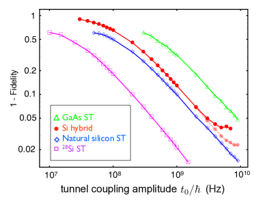
Fig. 2 shows the results of our dynamical simulation for the worst-case scenario of a rotation around the logical axis, using an equivalent gate sequence (see supplemental material). ( rotations can be achieved with much greater fidelity, since they can be performed without transforming into state .) Increasing the tunnel coupling improves the fidelity because it increases the speed of rotation, until the and anti-crossings overlap, at which point the fidelity flattens out. The point at which this occurs moves to higher frequency as increases.
Fig. 2 also shows analogous fidelity calculations for the exchange gate that implements rotations of singlet-triplet qubits Petta et al. (2005); Maune et al. (2012), which are implemented by pulsing to a value of the detuning at which the exchange coupling dominates over the inter-dot magnetic field difference Petta et al. (2005). There are competing effects in the fidelity when (i.e., when is small): the qubit becomes charge-like, and decoheres more quickly, but the gate speed also increases. In Fig. 2, the value of is chosen to yield the maximum value of the fidelity for every and in the simulations. Figure 2 shows our results for three physical systems: GaAs ( GHz, mT Assali et al. (2011)), natural Si ( MHz, T Assali et al. (2011)), and isotopically purified Si ( MHz, T Assali et al. (2011)). For a fixed tunnel coupling, increasing reduces the fidelity of the exchange gate. However, better fidelities can be achieved by increasing and simultaneously. Fig. 2 demonstrates that the fidelity of a pulse-gated hybrid qubit is comparable to that of a pulse-gated singlet-triplet qubit fabricated using natural silicon.
A different version of the pulse-gated quantum operation can be performed using a combination of slow ramps and fast pulses that yield adiabatic passage through the anticrossing between and Nakamura (2001) and Rabi oscillations at the anticrossing between and . Starting from a detuning that is more negative than , one first increases the detuning adiabatically through anticrossing (which transforms and has no effect on ), then pulses suddenly to anticrossing (which induces Rabi oscillations between and ), and finally decreases the detuning adiabatically through anticrossing (which transforms and has no effect on ). Using a protocol with these adiabatic portions could be very useful if the energy splitting at anticrossing is significantly larger than for anticrossing , which is conceivable because of the large differences of tunnel rates from different orbital states that have been observed in a silicon quantum dot Simmons et al. (2011). However, the qubit is much more susceptible to charge noise during the gating process, because of the markedly different charge distribution in than in and Gamble et al. (2012), and thus it is likely to be more difficult to perform high-fidelity gate operations using a partially adiabatic process than using the sequence of Rabi oscillations described above.
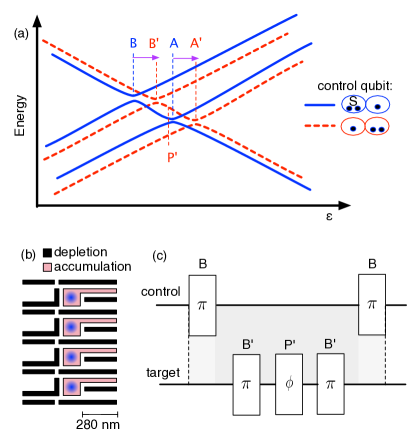
Two-qubit gates.—Two-hybrid qubit gates can be implemented by exploiting capacitive coupling Yamamoto et al. (2003); Shulman et al. (2012), as illustrated in Fig. 3. The charge distribution in state is substantially different than in , so there is a substantial Coulomb coupling that causes the location of the anticrossings and of the target qubit to depend on whether the control qubit is in state or in state , as shown in Fig. 3. Therefore, pulsing the target qubit to the detuning of anticrossing A converts the state of the target qubit to when the control qubit is in state but not in state . This dependence of the position of the anticrossings of the target qubit on the state of the control qubit enables the construction of a conditional two-qubit gate, as illustrated in Fig. 3(c). One first applies a B gate to the control qubit, which transforms , and then applies a gate sequence that changes the phase of the target qubit only if the control qubit is in state . 2D Thomas-Fermi modeling Stopa (1996) of the realistic device geometry shown in Fig. 3(b) and described in the supplemental information yields shifts in the anticrossing energies of meV, large enough for fast operations to be feasible.
Summary and Conclusions.—In summary, we have presented a method for performing pulse-gating on a hybrid qubit. The protocol is more complicated than for a charge qubit because the qubit states typically cannot be made energetically degenerate. We overcome this difficulty by exploiting avoided crossings at two different detunings between each of the two qubit states and an intermediate state. By introducing an additional phase gate at a third detuning point, we have shown that it is possible to implement arbitrary rotations of the logical qubit. We have derived a closed set of equations for the pulse sequences and performed dynamical simulations of the gates assuming realistic values for the dephasing. We also showed that two-qubit gates can be implemented by operating the control qubit in the charge regime to electrically enable or disable a rotation on the target qubit.
We thank Xuedong Hu, Jon Prance, and Zhan Shi for useful conversations. This work was supported in part by ARO (W911NF-08-1-0482) and NSF (DMR-0805045, PHY-1104660), and the National Science Foundation Graduate Research Fellowship (DGE-0718123).
Supplemental Information
Details of the Derivations of Eqs. 2-4.—Here, we outline the calculations of the control parameters , , for the single-qubit gate shown in Fig. 1(c).
A general rotation of a two-component spinor around the axis with angle is given by
| (5) |
where are Pauli matrices. The gate corresponds to an rotation of angle in the subspace of the full Hilbert space spanned by . During the course of the operation, states and gain a phase of . (We define all phases relative to .) Thus,
The gate corresponds to an rotation of angle in the subspace. During this operation, state gains a phase of . Thus,
The and gates are phase gates. During the operation, state gains a phase of relative to , while state gains a phase of . Similar considerations apply to Thus,
Computing the composite gate , we obtain the following rotation in the subspace:
We can decompose this into a sum of Pauli matrices using , where is the identity matrix, and . Comparing to Eq. (5), we obtain the results shown in Eqs. (2)-(4), up to an overall phase.
We note that an alternative and equivalent pulse sequence is obtained when , corresponding to the gate sequence . For the this gate sequence, we obtain identical results after making the substitutions .
Description of the modeled device.—The Thomas-Fermi calculations are performed on a realistic quadruple quantum dot gate geometry for an accumulation-mode device. Fig. 3(b) shows the primary gate pattern, in which metallic gates sit on a 10 nm thick Al2O3 layer on top of a Si/Si0.7Ge0.3 heterostructure containing a Si quantum well 35 nm beneath its surface. The Si0.7Ge0.3 layer is modeled as a dielectric with . The accumulation gates are positively biased, resulting in electron accumulation as indicated schematically on the diagram. The depletion gates provide tunability of tunnel barriers between the dots themselves and between each dot and its reservoir. Two large top gates sit on top of an additional 70 nm of Al2O3. The first, positively biased, establishes the reservoirs on the left-hand side of Fig. 3(b); the second, negatively biased, prevents any undesired accumulation on the right-hand side of Fig. 3(b).
References
- DiVincenzo (1995) D. DiVincenzo, Science, 270, 255 (1995).
- Preskill (1998) J. Preskill, Proc. R. Soc. Lond. A, 454, 469 (1998).
- Fisher (2003) A. Fisher, Philos. Trans. Roy. Soc. A, 361, 1441 (2003).
- Shi et al. (2012) Z. Shi, C. B. Simmons, J. R. Prance, J. K. Gamble, T. S. Koh, Y.-P. Shim, X. Hu, D. E. Savage, M. G. Lagally, M. A. Eriksson, M. Friesen, and S. N. Coppersmith, Phys. Rev. Lett., 108, 140503 (2012).
- Koppens et al. (2006) F. H. L. Koppens, C. Buizert, K. J. Tielrooij, I. T. Vink, K. C. Nowack, T. Meunier, L. P. Kouwenhoven, and L. M. K. Vandersypen, Nature, 442, 766 (2006).
- Levy (2002) J. Levy, Phys. Rev. Lett., 89, 147902 (2002).
- DiVincenzo et al. (2000) D. P. DiVincenzo, D. Bacon, J. Kempe, G. Burkard, and K. B. Whaley, Nature, 408, 339 (2000).
- Martinis et al. (2002) J. M. Martinis, S. Nam, J. Aumentado, and C. Urbina, Phys. Rev. Lett., 89, 117901 (2002).
- Pioro-Ladrière et al. (2008) M. Pioro-Ladrière, T. Obata, Y. Tokura, Y.-S. Shin, T. Kubo, K. Yoshida, T. Taniyama, and S. Tarucha, Nat. Phys., 4, 776 (2008).
- Hayashi et al. (2003) T. Hayashi, T. Fujisawa, H. D. Cheong, Y. H. Jeong, and Y. Hirayama, Phys. Rev. Lett., 91, 226804 (2003).
- Gorman et al. (2005) J. Gorman, D. G. Hasko, and D. A. Williams, Phys. Rev. Lett., 95 (2005), doi:10.1103/PhysRevLett.95.090502.
- Petta et al. (2006) J. R. Petta, A. C. Johnson, J. M. Taylor, A. Yacoby, M. D. Lukin, C. M. Marcus, M. P. Hanson, and A. C. Gossard, Physica E, 34, 42 (2006).
- Shinkai et al. (2009) G. Shinkai, T. Hayashi, T. Ota, and T. Fujisawa, Phys. Rev. Lett., 103, 056802 (2009).
- Petersson et al. (2010) K. D. Petersson, J. R. Petta, H. Lu, and A. C. Gossard, Phys. Rev. Lett., 105, 246804 (2010).
- Petta et al. (2005) J. R. Petta, A. C. Johnson, J. M. Taylor, E. A. Laird, A. Yacoby, M. D. Lukin, C. M. Marcus, M. P. Hanson, and A. C. Gossard, Science, 309, 2180 (2005).
- Laird et al. (2010) E. A. Laird, J. M. Taylor, D. P. DiVincenzo, C. M. Marcus, M. P. Hanson, and A. C. Gossard, Phys. Rev. B, 82, 075403 (2010).
- Gaudreau et al. (2011) L. Gaudreau, G. Granger, A. Kam, G. C. Aers, S. A. Studenikin, P. Zawadzki, M. Pioro-Ladrière, Z. R. Wasilewski, and A. S. Sachrajda, Nature Physics, 8, 54 (2011).
- Shulman et al. (2012) M. D. Shulman, O. E. Dial, S. P. Harvey, H. Bluhm, V. Umansky, and A. Yacoby, Science, 336, 202 (2012).
- Maune et al. (2012) B. M. Maune, M. G. Borselli, B. Huang, T. D. Ladd, P. W. Deelman, K. S. Holabird, A. A. Kiselev, I. Alvarado-Rodriguez, R. S. Ross, A. E. Schmitz, M. Sokolich, C. A. Watson, M. F. Gyure, and A. T. Hunter, Nature, 481, 344 (2012).
- Lidar et al. (1998) D. A. Lidar, I. L. Chuang, and K. B. Whaley, Phys. Rev. Lett., 81, 2594 (1998).
- Nielsen and Chuang (2000) M. A. Nielsen and I. L. Chuang, Quantum Computation and Quantum Information (Cambridge University Press, New York, 2000).
- Shi et al. (2011) Z. Shi, C. B. Simmons, J. Prance, J. K. Gamble, M. Friesen, D. E. Savage, M. G. Lagally, S. N. Coppersmith, and M. A. Eriksson, Appl. Phys. Lett., 99, 233108 (2011), arXiv:1109.0511.
- Petta et al. (2004) J. R. Petta, A. C. Johnson, C. M. Marcus, M. P. Hanson, and A. C. Gossard, Phys. Rev. Lett., 93, 186802 (2004).
- Viola et al. (1999) L. Viola, E. Knill, and S. Lloyd, Phys. Rev. Lett., 82, 2417 (1999).
- Gamble et al. (2012) J. K. Gamble, X. Hu, M. Friesen, and S. N. Coppersmith, Phys. Rev. B, 86, 035302 (2012), preprint arXiv:1203.6332.
- Barrett and Barnes (2002) S. D. Barrett and C. H. W. Barnes, Phys. Rev. B, 66, 125318 (2002).
- Assali et al. (2011) L. V. C. Assali, H. M. Petrilli, R. B. Capaz, B. Koiller, X. Hu, and S. Das Sarma, Phys. Rev. B, 83, 165301 (2011).
- Nakamura (2001) Y. Nakamura, Nonadiabatic Transition: Concepts, Basic Theories and Applications (World Scientific, London, 2001).
- Simmons et al. (2011) C. B. Simmons, J. R. Prance, B. J. Van Bael, T. S. Koh, Z. Shi, D. E. Savage, M. G. Lagally, R. Joynt, M. Friesen, S. N. Coppersmith, and M. A. Eriksson, Phys. Rev. Lett., 106, 156804 (2011).
- Stopa (1996) M. Stopa, Phys. Rev. B, 54, 13767 (1996).
- Yamamoto et al. (2003) T. Yamamoto, Y. A. Pashkin, O. Astafiev, Y. Nakamura, and J. S. Tsai, Nature, 425, 941 (2003).