Control of microwave signals using circuit nano-electromechanics
Abstract
Microwave superconducting coplanar waveguide resonators are crucial elements in sensitive astrophysical detectors day_broadband_2003 and circuit quantum electrodynamics (cQED) Wallraff2004 . Coupled to artificial atoms in the form of superconducting qubits vion_manipulating_2002 ; Clarke2008 , they now provide a technologically promising and scalable platform for quantum information processing tasksWallraff2004 ; Houck2007 ; Majer2007 ; Schoelkopf2008 ; Mariantoni2011 . Coupling these circuits, in situ, to other quantum systems, such as molecules Rabl2006 ; Andre2006 , spin ensembles Schuster2010 ; Kubo2011 , quantum dots frey_dipole_2012 or mechanical oscillators Regal2008 ; Rocheleau2010 ; Marquardt2009 ; Kippenberg2008 has been explored to realize hybrid systems with extended functionality. Here, we couple a superconducting coplanar waveguide resonator to a nano-mechanical oscillator, and demonstrate all-microwave field controlled slowing, advancing and switching of microwave signals. This is enabled by utilizing electromechanically induced transparency Weis2010 ; Safavi-Naeini2011 ; Teufel2011 , an effect analogous to electromagnetically induced transparency (EIT) in atomic physics Fleischhauer2005 . The exquisite temporal control gained over this phenomenon provides a route towards realizing advanced protocols for storage of both classical and quantum microwave signals Clerk2012 ; Braunstein2003 ; Tian2012 , extending the toolbox of quantum control techniques of the microwave field.
Cavity opto- and electro-mechanical systems Marquardt2009 ; Kippenberg2008 realize parametric coupling of an electromagnetic resonance to a mechanical mode, which enables a wide range of phenomena including displacement measurements, sideband cooling or amplification of mechanical motion. In the microwave domain, this physics has been explored by coupling of superconducting cavities to micro- and nano-mechanical oscillators Regal2008 ; Teufel2011 ; Rocheleau2010 enabling efficient transduction of mechanical motion with an imprecision below the level of the zero point motion Teufel2009 , electro-mechanical sideband cooling to the quantum ground state Teufel2011b ; Rocheleau2010 , and electromechanical amplification of microwave signals massel_microwave_2011 . Moreover the mutual coupling of microwaves and mechanical oscillator modifies the microwave response leading to the phenomenon of electromechanically induced transparency Weis2010 . Here we demonstrate that superconducting circuit nano-electromechanical systems enable a novel class of control phenomena over the microwave field. Exploiting the coupling of a superconducting microwave cavity to a nano-mechanical oscillator, we demonstrate tunable, sub- and superluminal microwave pulse propagation, mediated by the nano-mechanical oscillator’s response. The high mechanical quality factor enables a maximum delay of microwave pulses exceeding 3 ms, corresponding to an effective coaxial cable length of several hundreds of kilometers. Importantly, this delay is achieved with negligible losses and pulse distortion. Moreover, we explore the circuit nano-electromechanical response to a time-dependent control field, which is required for a series of advanced protocols including quantum state transfer and storage Verhagen2011 ; Romero-Isart2011 , fast sideband cooling Wang2011a , as well as switching, modulation and routing of classical and quantum microwave signals. To this end, we demonstrate all-microwave field controlled switching and show that counterintuitive regimes can be found in which the switching time can be much faster than the mechanical oscillator energy decay time. Finally, we also demonstrate mapping of the mechanical (Duffing) nonlinearity into the microwave domain.
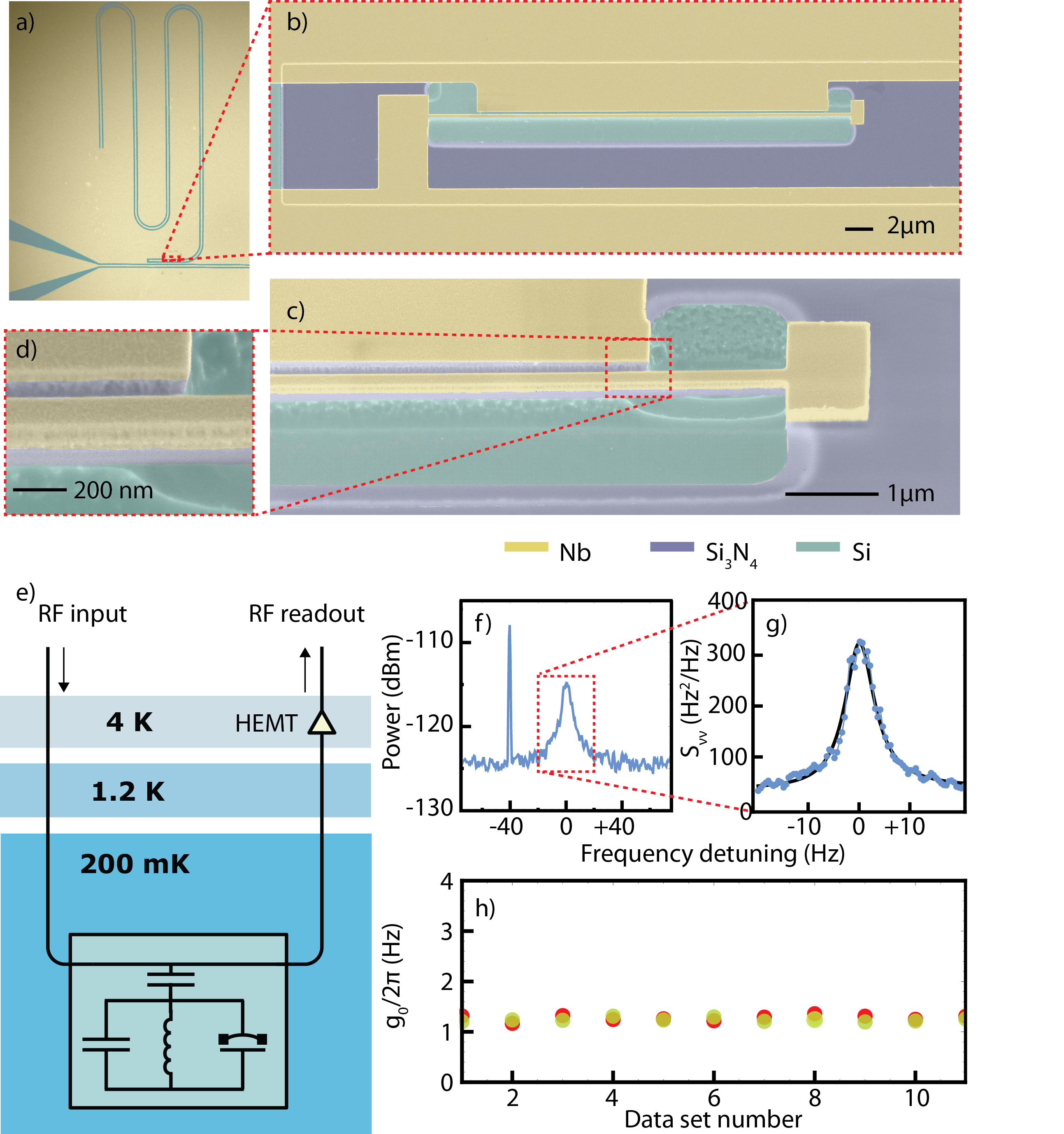
We investigate these phenomena in a Nb superconducting circuit nano-electromechanical system (similar in geometry to the ones studied in Refs. Regal2008 ; Rocheleau2010 ) consisting of a quarter-wavelength coplanar waveguide (CPW) resonator day_broadband_2003 (Figure 1), parametrically coupled to a nano-mechanical oscillator, consisting of a stoichometric, high stress beam coated with Nb. The microwave resonator studied in this work exhibits a fundamental resonance frequency of GHz and has a linewidth kHz of which are due to external coupling to the feedline. The Nb/ composite nano-mechanical beam has dimensions of nmnm and shows at cryogenic temperatures very low dissipation(), with a damping rate of Hz resonating at MHz. This system thus resides in the resolved sideband regime as . The thermal decoherence rate of the mechanical oscillator is kHz. Here, is the thermal equilibrium phonon occupancy at the dilution refrigerator temperature of ca. 200 mK. This temperature is far below the superconducting transition temperature of Nb (9.2 K) and significantly suppresses the thermal excitation of the microwave cavity, as mK, where is the reduced Planck constant and is the Boltzmann constant.
The interaction between the mechanical oscillator and the microwave coplanar waveguide resonator is formally equivalent to the optomechanical interaction Marquardt2009 ; Kippenberg2008 and quantified by the vacuum coupling rate Gorodetsky2010 in the corresponding interaction Hamiltonian
| (1) |
where is the intra-cavity photon number operator, and , are the ladder operators of the mechanical oscillator. The vacuum coupling rate is the product of the electro-mechanical frequency pulling parameter , denoting the cavity resonance frequency change upon mechanical displacement, and the mechanical resonator’s zero-point fluctuation , where is the effective mass of the beam. The coupling rate is calibrated by applying a known frequency modulation to a microwave tone coupled into the cavity Gorodetsky2010 (Figure 1d)). The spectrum of the homodyne readout is shown in Figure 1e) and f), yielding a measured coupling rate of , independent of the microwave power reaching the coplanar waveguide cavity after several stages of attenuation in the refrigerator.
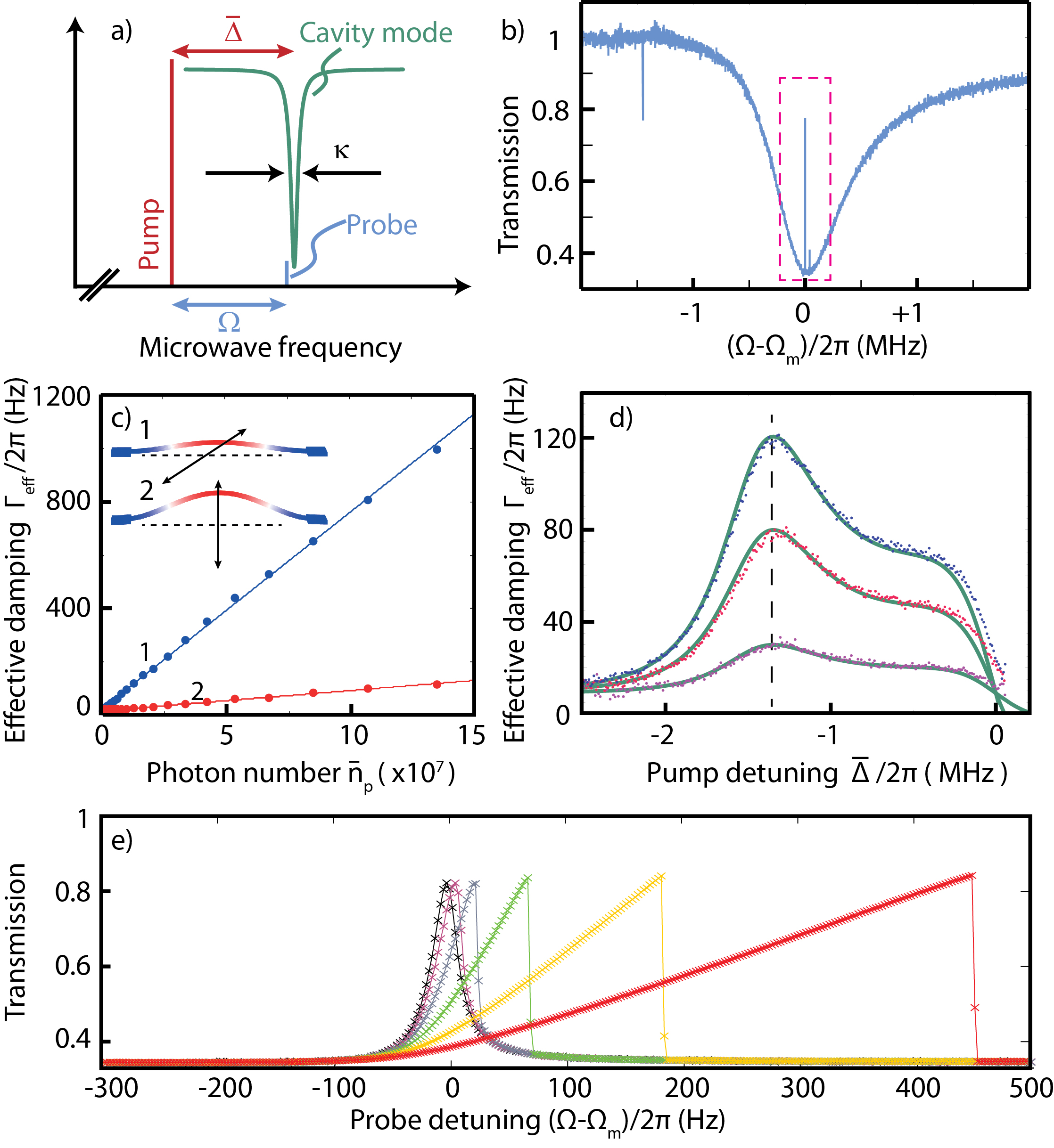
In our system, the effective radiation pressure force that is reflected by the electromechanical interaction Hamiltonian (), gives rise to a modification of the dynamics of the mechanical oscillator. Moreover, it leads to an interaction between two microwave fields sent simultaneously into the cavity Teufel2011 ; massel_microwave_2011 ; Agarwal2010 . This latter phenomenon which is also referred to as electromechanically induced transparency arises as the overall radiation pressure of the two fields, a strong pump at frequency and a weak probe field at frequency , drives the motion of the mechanical oscillator at the two fields’ beat frequency . The oscillation is resonantly enhanced if the frequency difference between the two fields coincides with . The driven motion, in turn, generates Stokes- and anti-Stokes sidebands on the pump field, which can interfere with the probe field leading to an induced transparency (or amplification for a blue detuned pump massel_microwave_2011 ). The resulting transmission coefficient of the probe field is given by
| (2) |
where and the susceptibility of the mechanical oscillator . Here, denotes the classical expectation value of the intra-cavity pump photon number and is the effective detuning of the pump field with the static mechanical displacement . Figure 2 shows the measured probe transmission in the presence of a red-detuned pump , resulting in an induced transmission window, which coincides with the microwave cavity resonance. The width of this window in the weak coupling regime is given by the effective mechanical damping rate , with resulting from radiation-pressure induced dynamical backaction Teufel2008 ; Rocheleau2010 ; Teufel2011b ; Kippenberg2005 ; Schliesser2006 ; Gigan2006 ; Arcizet2006a .
We study this response experimentally using a vector network analyzer to generate the probe tone, and analyze its direct transmission, in this case without the homodyne interferometer. A standard microwave generator provides the pump tone which is simultaneously coupled into the cavity (cf. the SI for a more detailed description of the employed measurement setup). A systematic investigation of the electromechanical effective damping as a function of pump detuning and pump intra-cavity photon number shows excellent agreement with theory (Figure 2 a, b). Importantly, these measurements, together with the independently determined , can be used to provide an independent calibration of the intra-cavity pump photon number , and therefore the microwave attenuation in the refrigerator before entering the microwave cavity (62dB attenuation in this measurement setup).
Interestingly, the nano-electromechanical system shows significant deviations from the standard electromechanically induced transparency behavior already for moderate pump power () if the probe power is increased to more than (Figure 2c). Strongly asymmetric lineshapes of the transmission window are observed. This asymmetry increases with an increasing probe power - much in contrast to the fully linear theory. This nonlinearity is a direct consequence of the fact that the transmission window is modified by scattering of photons induced by the mechanical oscillator. The latter exhibits a Duffing nonlinearity Nayfeh1979 ; Kozinsky2006 with a critical amplitude of ca. 2 nm and a Duffing parameter , which is compatible with earlier experiments Unterreithmeier2010 . This value is independently determined in a set of measurements, in which the oscillator is driven by an externally applied low-frequency AC voltage via the DC port of a bias-tee (see SI). The full electromechanical dynamics (including the Duffing nonlinearity for 0) are captured by the set of equations in the Fourier domain :
| (3) |
| (4) |
for the amplitude of the intra-cavity probe field and and the mechanical oscillation . Here, the resolved-sideband regime is assumed (), as well as a large mechanical quality factor , so that that the dynamic (resonant) response of the mechanical oscillator is much larger than the static displacement (cf. SI). Furthermore, denotes the power of the probe field sent towards the cavity. As seen in Figure 2c, the Duffing nonlinearity is thus mapped directly onto the transmission of the probe field, yielding nonlinear behavior for probe powers as low as sent towards the cavity. The resulting bistability of the microwave transmission could be used for non-volatile memory applications mahboob_bit_2008 .
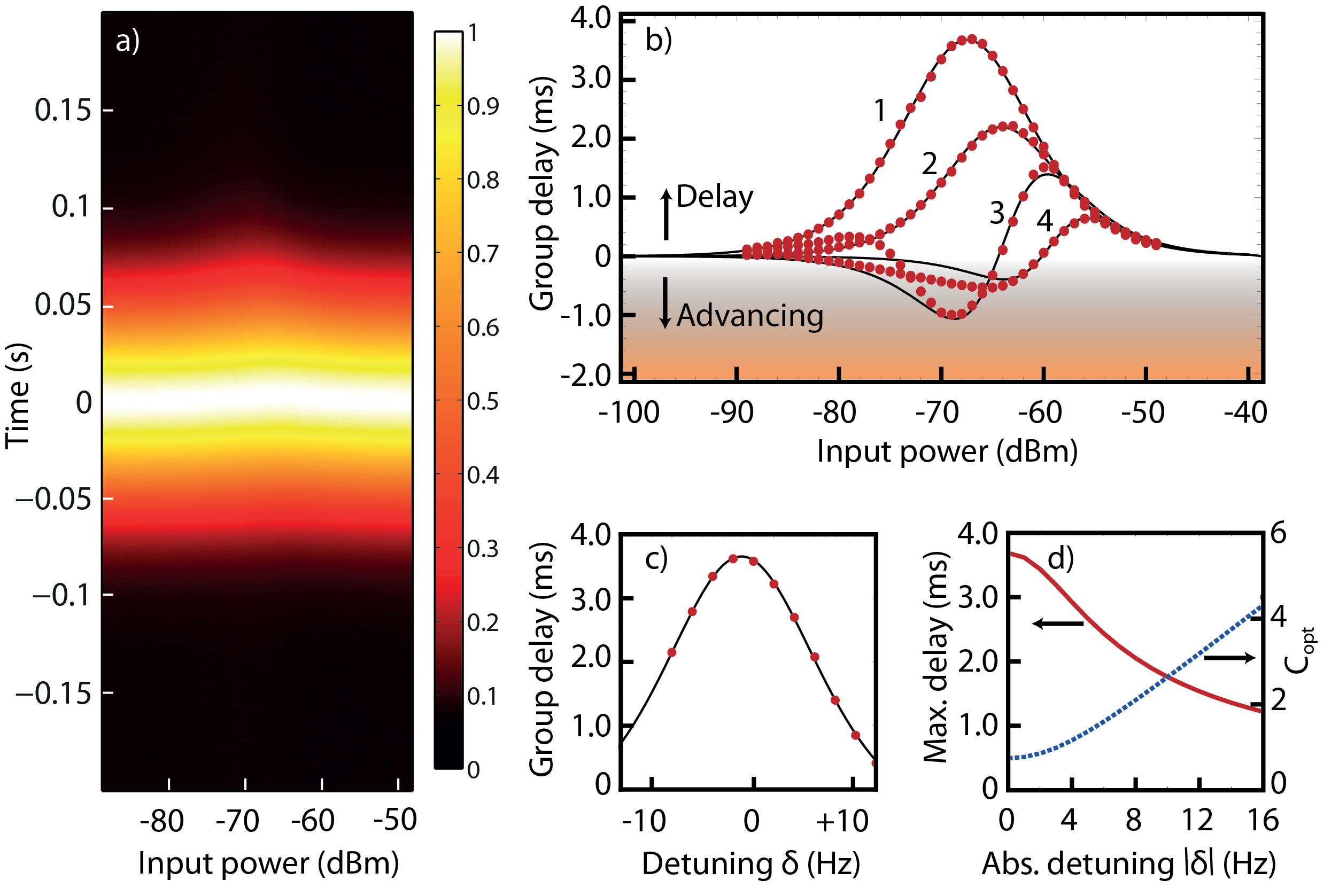
For lower probe powers, the radiation-pressure induced oscillation amplitude of the mechanical mode remains well below the threshold for non-linear oscillations. In this regime, the transmission of the probe field is well described by equation (2). Importantly, the presence of the pump beam does not only induce a strong modification of the transmission of the probe field, but also leads at the same time to a fast variation of the phase of the transmitted probe field across the transmission window. This can lead to significant group delays Schliesser2010 ; Weis2010 ; Safavi-Naeini2011 ; Jiang2011a , in analogy to that achieved with the electromagnetically induced transparency in atomic Phillips2001 ; Liu2001 and in solid state media Longdell2005 . The delay is given by
| (5) |
for a microwave probe pulse whose center frequency falls into the transmission window. In particular, in the resolved-sideband case and for red-detuned pumping (), the group delay is given by (see SI and Safavi-Naeini2011 )
| (6) |
where denotes the electromechanical cooperativity parameter Groblacher2009a with the coupling rate The group delay reaches its maximum value
| (7) |
as the cooperativity approaches .
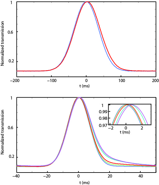
To experimentally explore this predicted behavior, microwave probe pulses are generated by modulating the amplitude of a weak (-108 dBm) probe tone derived from a microwave generator. The Gaussian-shaped envelope functions (FWHM duration 83 ms) are generated with an arbitrary waveform generator. The emission of a probe pulse is synchronized with the acquisition of the transmitted probe field. Simultaneously, a continuous-wave pump tone is sent to the cavity (see SI for details). Figure 3 shows the results of these measurements. A delay of the probe pulses can be observed when the power of the pump is varied. The maximum group delay achieved is 3.5 ms with negligible losses and pulse distortion as shown in Figure 3 a, b).
In the case of a slightly detuned probe tone, , a good approximation of the group delay is given by
| (8) |
This allows for a negative group delay, i.e. the advancing of the microwave pulses, with sufficient detuning such that . The probe delay measured when both pump tone power and probe tone detuning are varied, reveals an excellent agreement with the full theory (Figure 3 b, c, d).
For a number of advanced optomechanical protocols for both quantum and classical applications Verhagen2011 ; Romero-Isart2011 ; Wang2011a , it is necessary to dynamically tune the coupling rate
| (9) |
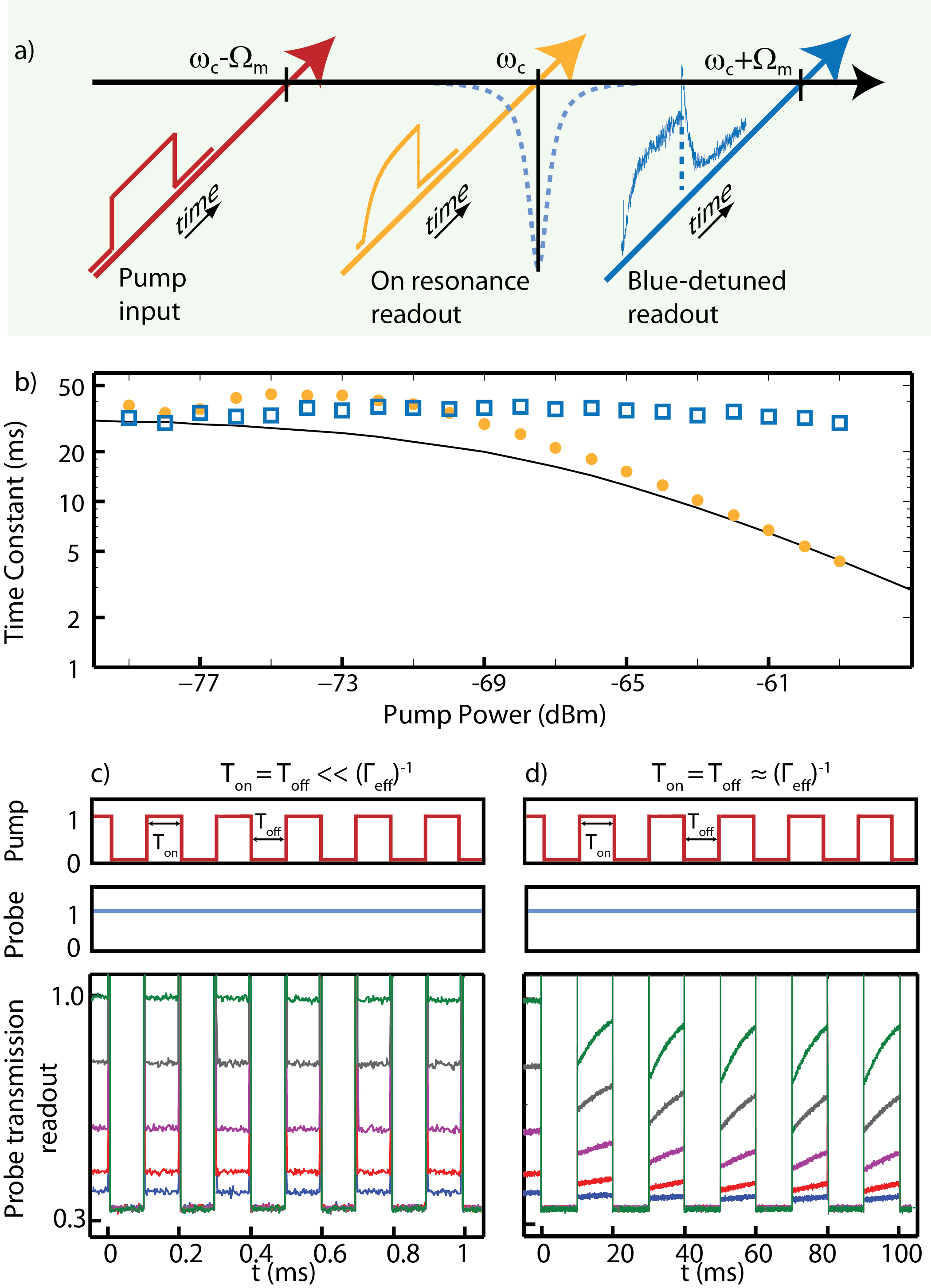
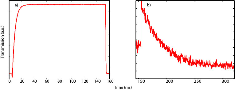
For switching applications, the response of the system can be limited both by the dynamics of the mechanical mode amplitude () as well as the pump field (). In the following, we explore these dynamics experimentally. To this end, the pump tone is tuned to the red sideband (), and switched by modulating its amplitude with rectangular pulses of duration. The probe tone, tuned in resonance with the cavity (), is constantly on, and its transmission is recorded. While the intra-cavity pump power rings up on a time scale , the transmission of the probe beam builds up only at a significantly smaller rate of , at which the mechanical oscillation amplitude converges towards its steady-state value (see SI). Figure 4b) shows the characteristic timescales for probe transmission variations as a function of pump power. Upon switching off of the pump field, the probe transmission immediately drops, as the pump field (giving rise to destructive interference) decays from the resonator at a fast timescale of . It is important to note that after switching off the pump and the corresponding field enhanced optomechanical coupling rate , the mechanical oscillation still prevails, and consequently a small fraction of the probe field is scattered to different (Stokes and anti-Stokes) frequencies. It can be shown that the modification of the transmission (with respect to the case where the coherent excitation of the mechanical oscillator’s amplitude has vanished) is negligible, since in this regime the change in transmission due to the finite amplitude of the mechanical oscillator is given by , with and being the amplitude of motion. For the amplitudes concerned in this work, is typically at the level of <1 %. However, once the mechanical oscillation is excited to its steady state amplitude by the beating of the pump and probe fields, it decays only at a very slow rate of in the absence of the pump beam. Therefore, advantageously for the switching, if a series of pump pulses is applied, whose period is much shorter than this timescale, the transmission of the probe follows the pump modulation, determined by the decay time of the microwave cavity (Figure 4e). We show the counterintuive regime where the switching time can be substantially faster than the slowest timescale in the problem (i.e. the inverse effective mechanical damping rate, ) and is limited only by the microwave cavities decay time ( ). In a regime of intermediate pulse periods, the mechanical amplitude partially decays between the pump pulses, leading to a slower recovery of the full probe transmission when the pump is switched back on. Switching is possible if the mechanical mode does not decay significantly between the individual pump pulses (). During longer off-times (), the mechanical oscillator relaxes towards its equilibrium position, however suffices already to drive it back to its steady state oscillation, at which the probe tone has a transmission transparency.
Note, that while in the above electromechanical-switching experiments the pump tone is modulated, and the probe tone remains stationary, utilizing the demonstrated temporal control in conjuction with probe pulses enables to achieve storage of pump pulses in the mechanical oscillator via conversion of the pump pulse into a coherent excitation of the mechanical oscillator Braunstein2003 ; Fiore2011 .
In conclusion, we have demonstrated that electromechanically induced transparency can be used in electromechanical systems to manipulate the transmission and delay of a microwave signal in a fully integrated architecture without the need of photon detection and regeneration. Interestingly, the switching can be faster than the timescale of the mechanical oscillator’s energy decay. Using electromechanically induced transparency, both classical microwave signals can be switched, or routed hoi_demonstration_2011 through arrays of electromechanical systems, while the associated delays enable synchronization of microwave pulses. Both delay and advancing of pulses have been achieved. The employed microfabrication techniques offer in this context a far-reaching flexibility in the design of both mechanical and microwave properties–including carrier frequencies and bandwidth–as well as the overall architecture of complex networks. The delay and advancing of pulses may also be extended to single microwave photon pulses Houck2007 . The prerequisites for preserving the single photon state is that the thermal decoherence time () is long compared to the photon delay/advance time. The pulse duration (i.e. bandwith of the pulses) is limited by the width of the transparency window () to avoid pulse distortion, implying that the condition needs to be satisfied. In the weak coupling limit (), the latter is equivalent to a cooperativity exceeding the thermal occupation .
While our system already reaches coupling rates exceeding the mechanical decoherence rate even at a moderate cryogenic temperature, a larger Teufel2011 ; Verhagen2011 , or a simple improvement in the measurement setup, allowing a larger pump field (sustainable by the employed Nb cavities) would in principle already be sufficient for the system to reside in the coherent coupling regime . Combining the system with the powerful advances in the generation and detection of single microwave photons Houck2007 , thereby may enable control over the propagation of nonclassical states using the electromechanical architecture, and allow for complete storage and retrieval of a microwave quantum state in long-lived mechanical excitations.
Methods:
1. Nano-electromechanically coupled system: For the coplanar waveguide (CPW) structures a characteristic impedance of is realized with a m wide center stripline separated by a gap of m from the ground plane (see Figure 1). The one-sided cavity with a typical length of mm is capacitively coupled to a CPW feedline on one end, and shorted on the other end. This CPW cavity is patterned into a Nb thin film deposited on top of a Si substrate. Frequency multiplexing is realized by embedding on a single chip several cavities of different length coupled to a single CPW feedline. The nano-mechanical object integrated in the cavity is a high-aspect-ratio beam, m long, nm wide and has a thickness of nm, which consists of nm thick Nb on top of nm thick tensile-stressed . The high tensile-stress of overcomes the compressive stress of Nb.
2. Low temperature measurement setup: All experiments have been performed in a dilution refrigerator at around 200 mK. In the dilution refrigerator there are three signal lines: two coaxial-cable lines connecting the two ends of the sample feedline for the microwave input- and output-signal, and a low-frequency line to carry a drive signal (MHz) that enables resonant excitation of the nano-mechanical beam via Coulomb force. A sample of dimension 10 mm 6 mm is mounted in a gold-plated copper box. SMA coaxial connector at each end is silver-glued to the CPW feedline, transmits signals to/from the sample. Thermal noise from the tones at room temperature is suppressed using attenuators at successive temperature stages, and by the inertial attenuation of the coaxial cable. The DC-block filter besides the sample prevents the DC current in the overall transmission loop. A HEMT amplifier is anchored at 4K and is isolated from the sample output by a circulator. For more details of the individual measurements, please refer to the SI.
Acknowledgements:
TJK acknowledges support support by the NCCR of Quantum Engineering and an ERC Starting Grant (SiMP) and the Swiss National Science Foundation (SNF). Financial support from the German Excellence Initiative via the “Nanosystems Initiative Munich” (NIM) is gratefully acknowledged. Samples were grown and fabricated at the Center of MicroNanotechnology (CMi) at EPFL. The authors acknowledge the assistance of Stefan Weis, Thomas Niemczyk and Haytham Chibani in fabrication, Pertti Hakonen and Pasi Lähteenmäki for measurement in the early phase of the project.
Author contributions:
XZ designed and fabricated the samples. The cryogenic measurement setup was implemented by FH and HH. FH, XZ, HH and AS performed the experiments. XZ and AS performed theoretical modeling and analysis of the data. XZ wrote the paper with guidance from AS and TJK. All authors discussed the results and contributed to the final version of the manuscript.
References
- (1) Day, P. K., LeDuc, H. G., Mazin, B. A., Vayonakis, A., and Zmuidzinas, J. Nature 425(6960), 817–821 October (2003).
- (2) Wallraff, A., Schuster, D. I., Blais, A., Frunzio, L., Huang, R.-S., Majer, J., Kumar, S., Girvin, S. M., and Schoelkopf, R. J. Nature 431(7005), 162–167 September (2004).
- (3) Vion, D., Aassime, A., Cottet, A., Joyez, P., Pothier, H., Urbina, C., Esteve, D., and Devoret, M. H. Science 296(5569), 886–889 March (2002).
- (4) Clarke, J. and Wilhelm, F. K. Nature 453(7198), 1031–1042 June (2008).
- (5) Houck, A. A., Schuster, D. I., Gambetta, J. M., Schreier, J. A., Johnson, B. R., Chow, J. M., Frunzio, L., Majer, J., Devoret, M. H., Girvin, S. M., and Schoelkopf, R. J. Nature 449(7160), 328–331 September (2007).
- (6) Majer, J., Chow, J. M., Gambetta, J. M., Koch, J., Johnson, B. R., Schreier, J. A., Frunzio, L., Schuster, D. I., Houck, A. A., Wallraff, A., Blais, A., Devoret, M. H., Girvin, S. M., and Schoelkopf, R. J. Nature 449(7161), 443–447 September (2007).
- (7) Schoelkopf, R. J. and Girvin, S. M. Nature 451(7179), 664–669 February (2008).
- (8) Mariantoni, M., Wang, H., Yamamoto, T., Neeley, M., Bialczak, R. C., Chen, Y., Lenander, M., Lucero, E., O’Connell, A. D., Sank, D., Weides, M., Wenner, J., Yin, Y., Zhao, J., Korotkov, A. N., Cleland, A. N., and Martinis, J. M. Science 334(6052), 61–65 July (2011).
- (9) Rabl, P., DeMille, D., Doyle, J. M., Lukin, M. D., Schoelkopf, R. J., and Zoller, P. Physical Review Letters 97(3), 033003 July (2006).
- (10) André, A., DeMille, D., Doyle, J. M., Lukin, M. D., Maxwell, S. E., Rabl, P., Schoelkopf, R. J., and Zoller, P. Nature Physics 2(9), 636–642 (2006).
- (11) Schuster, D. I., Sears, A. P., Ginossar, E., DiCarlo, L., Frunzio, L., Morton, J. J. L., Wu, H., Briggs, G. A. D., Buckley, B. B., Awschalom, D. D., and Schoelkopf, R. J. Phys. Rev. Lett. 105, 140501 Sep (2010).
- (12) Kubo, Y., Grezes, C., Dewes, A., Umeda, T., Isoya, J., Sumiya, H., Morishita, N., Abe, H., Onoda, S., Ohshima, T., Jacques, V., Dréau, A., Roch, J.-F., Diniz, I., Auffeves, A., Vion, D., Esteve, D., and Bertet, P. Phys. Rev. Lett. 107, 220501 Nov (2011).
- (13) Frey, T., Leek, P. J., Beck, M., Blais, A., Ihn, T., Ensslin, K., and Wallraff, A. Physical Review Letters 108(4), 046807 January (2012).
- (14) Regal, C. A., Teufel, J. D., and Lehnert, K. W. Nature Physics 4, 555–560 (2008).
- (15) Rocheleau, T., Ndukum, T., Macklin, C., Hertzberg, J. B., Clerk, A. A., and Schwab, K. C. Nature 463(7277), 72–75 Jan (2010).
- (16) Marquardt, F. and Girvin, S. M. Physics 2, 40 (2009).
- (17) Kippenberg, T. J. and Vahala, K. J. Science 321, 1172–1176 (2008).
- (18) Weis, S., Rivière, R., Deléglise, S., Gavartin, E., Arcizet, O., Schliesser, A., and Kippenberg, T. J. Science 330, 1520–1523 (2010).
- (19) Safavi-Naeini, A. H., Alegre, T. P. M., Chan, J., Eichenfield, M., Winger, M., Lin, Q., Hill, J. T., Chang, D. E., and Painter, O. Nature 472(7341), 69–73 April (2011).
- (20) Teufel, J. D., Li, D., Allman, M. S., Cicak, K., Sirois, A. J .and Whittaker, J. D., and Simmonds, R. W. Nature 471 (2011).
- (21) Fleischhauer, M., Imamoglu, A., and Marangos, J. P. Review of Modern Physics 77, 633–673 (2005).
- (22) Wang, Y.-D. and Clerk, A. A. Phys. Rev. Lett. 108, 153603 Apr (2012).
- (23) Zhang, J., Peng, K., and Braunstein, S. L. Phys. Rev. A 68, 013808 Jul (2003).
- (24) Tian, L. Phys. Rev. Lett. 108, 153604 Apr (2012).
- (25) Teufel, J. D., Donner, R., Castellanos-Beltran, M. A., Harlow, J. W., and Lehnert, K. W. Nature Nanotechnology 4, 820–823 (2009).
- (26) Teufel, J. D., Donner, T., Li, D., Harlow, J. W., Allman, M. S., Cicak, I. K., Sirois, A. J., Whittaker, J. D., Lehnert, K. W., and Simmonds, R. W. Nature 475(7356),359–363 July (2011).
- (27) Massel, F., Heikkilä, T. T., Pirkkalainen, J., Cho, S. U., Saloniemi, H., Hakonen, P. J., and Sillanpää, M. A. Nature 480(7377), 351–354 December (2011).
- (28) Verhagen, E., Deléglise, S., Weis, S., Schliesser, A., and Kippenberg, T. J. Nature 482(7383), 63–67 February (2012).
- (29) Romero-Isart, O., Pflanzer, A. C., Juan, M. L., Quidant, R., Kiesel, N., Aspelmeyer, M., and Cirac, J. I. Physical Review Astroparticle Physics 83(1), 013803 Jan (2011).
- (30) Wang, X., Vinjanampathy, S., Strauch, F. W., and Jacobs, K. Physical Review Letters 107(17), 177204 October (2011).
- (31) Gorodetsky, M., Schliesser, A., Anetsberger, G., Deleglise, S., and Kippenberg, T. J. Optics Express 18, 23236–23246 (2010).
- (32) Agarwal, G. S. and Huang, S. Physical Review A 81(4), 041803 April (2010).
- (33) Teufel, J. D., Harlow, J. D., Regal, C. A., and Lehnert, K. W. Physical Review Letters 101, 197203 (2008).
- (34) Kippenberg, T. J., Rokhsari, H., Carmon, T., Scherer, A., and Vahala, K. J. Physical Review Letters 95, 033901 (2005).
- (35) Schliesser, A., Del’Haye, P., Nooshi, N., Vahala, K., and Kippenberg, T. Physical Review Letters 97, 243905 (2006).
- (36) Gigan, S., Böhm, H. R., Paternosto, M., Blaser, F., Langer, G., Hertzberg, J. B., Schwab, K. C., Bäuerle, D., Aspelmeyer, M., and Zeilinger, A. Nature 444, 67–70 (2006).
- (37) Arcizet, O., Cohadon, P.-F., Briant, T., Pinard, M., and Heidmann, A. Nature 444, 71–74 (2006).
- (38) Ali H. Nayfeh, D. T. M. Nonlinear Oscillations. Wiley, (1979).
- (39) Kozinsky, I., Postma, H. W. C., Bargatin, I., and Roukes, M. L. Applied Physics Letters 88(25), 253101–253101–3 June (2006).
- (40) Unterreithmeier, Q. P., Faust, T., and Kotthaus, J. P. Physical Review B 81(24), 241405 June (2010).
- (41) Mahboob, I. and Yamaguchi, H. Nature Nanotechnology 3(5), 275–279 April (2008).
- (42) Schliesser, A. and Kippenberg, T. J. In Advances in atomic, molecular and optical physics, Arimondo, E., Berman, P., and Lin, C. C., editors, volume 58, chapter 5, 207–323. Elsevier Academic Press (2010).
- (43) Jiang, C., Chen, B., and Zhu, K. EPL (Europhysics Letters) 94(3), 38002 May (2011).
- (44) Phillips, D. F., Fleischhauer, A., Mair, A., Walsworth, R. L., and Lukin, M. D. Physical Review Letters 86, 783–786 (2001).
- (45) Liu, C., Dutton, Z., Behroozi, C., and Hau, L. Nature 409, 490–493 (2001).
- (46) Longdell, J. J., Fraval, E., Sellars, M. J., and Manson, N. B. Physical Review Letters 95(6), 063601 (2005).
- (47) Gröblacher, S., Hammerer, K., Vanner, M. R., and Aspelmeyer, M. Nature 460, 724–727 (2009).
- (48) Fiore, V., Yang, Y., Kuzyk, M. C., Barbour, R., Tian, L., and Wang, H. Phys. Rev. Lett. 107, 133601 Sep (2011).
- (49) Hoi, I., Wilson, C. M., Johansson, G., Palomaki, T., Peropadre, B., and Delsing, P. Physical Review Letters 107(7), 073601 (2011).
Part I Supplementary Information -Control of microwave signals using circuit nano-electromechanics
I determination of the vacuum coupling rate
The vacuum optomechanical coupling rate quantifies the strength of electromechanical coupling, analogous to cavity quantum electrodynamics. Assuming (with : Boltzmann constant, : temperature, : reduced Planck constant, : mechanical frequency), the spectral density of fluctuations of the cavity resonance frequency induced by mechanical displacement are given by Gorodetsky2010
| (1) |
where is the frequency pulling parameter, and is the mechanical damping rate. The integration of equation1) gives
| (2) |
where is the mean mechanical occupancy. The fluctuations of the detected homodyne signal can be expressed as
| (3) |
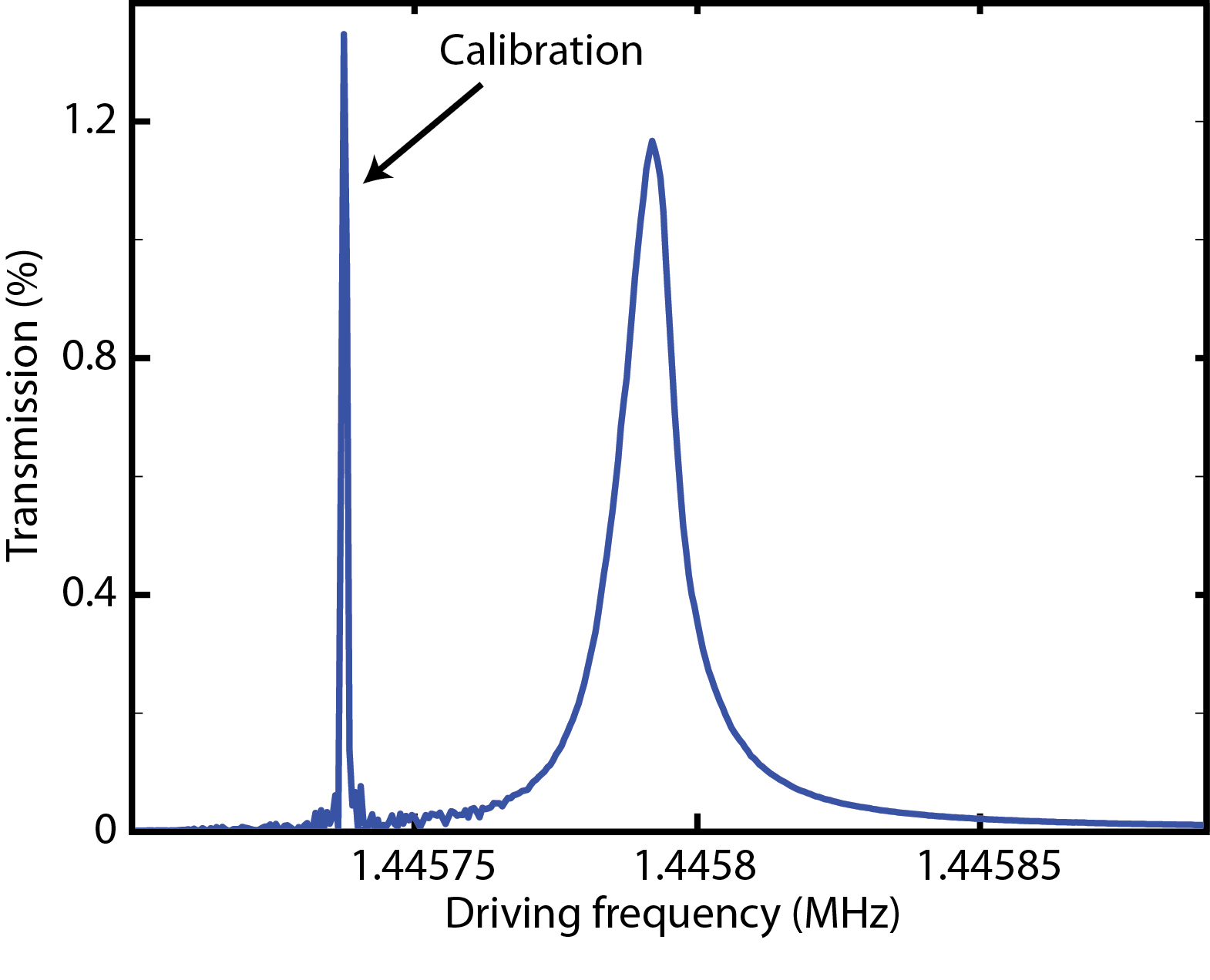
where the transduction function is calibrated by applying a frequency modulation of the pump tone at frequency Hz, with a modulation index of . As the effective noise bandwidth chosen in the spectral analyzer is much narrower than the spectral features of the mechanical mode, and assuming the signal at is dominated by the modulation, the transduction function can then be calibrated in absolute terms at this frequency, via the relation
| (4) |
where ENBW is the bandwidth given in direct frequency, i.e. in Hz. With the homodyne detection at zero detuning (), i.e. the pump tone is on cavity resonance , in this experiment, the transduction function is sufficiently constant () over the relevant range of frequencies. With equation (2)-(4), the vacuum coupling rate is derived from the measurement, knowing the mechanical occupancy number , via Gorodetsky2010
| (5) |
II Sample Fabrication
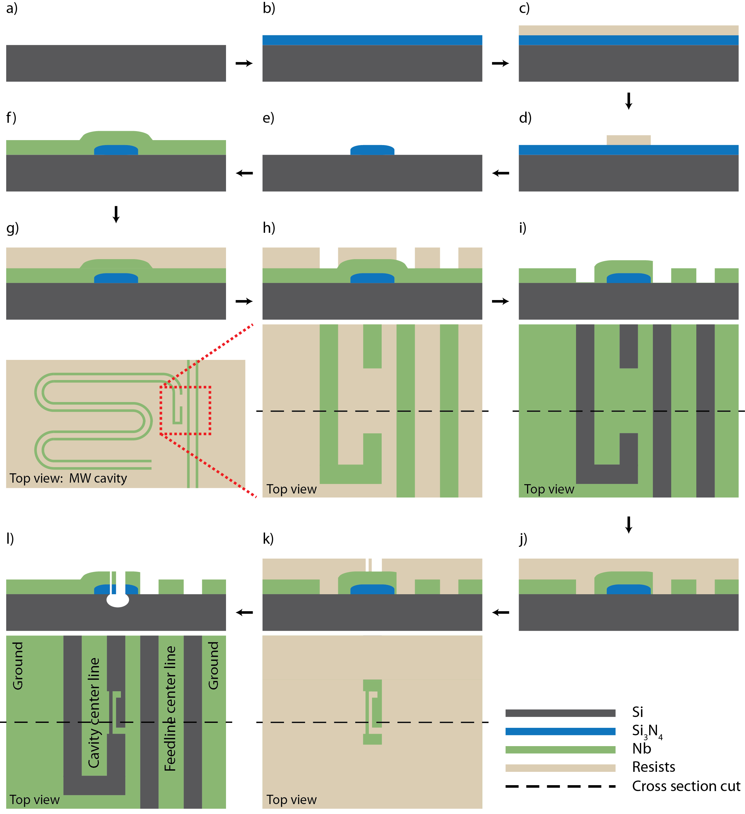
The fabrication starts with a Si substrate (Figure S1 a)). A high tensile-stressed layer of 100 nm is deposited with low pressure chemical vapor deposition (LPCVD) on top of the Si substrate (Figure. S1 b)). is patterned into small patches using electron beam (e-beam) lithography, reactive ion etching (RIE) and buffered hydrogen fluoride (HF) etching. The mechanical beams will later sit on those patches (Figure. S1 c,d,e)). A thin Nb film of 130 nm is deposited on top of the substrate, and microwave cavities are patterned with e-beam lithography and the Nb film is etched through with RIE (Figure. S1 f,g,h,i)). A short patch of Nb is left on top of the patch, which is between the center and ground of the MW cavity CPWs. At this exact location, the mechanical beam is patterned with e-beam lithography and released in the following fabrication steps, i.e., anisotropic- and isotropic- RIE. (Figure. S1 j,k,l))
III Measurement setups
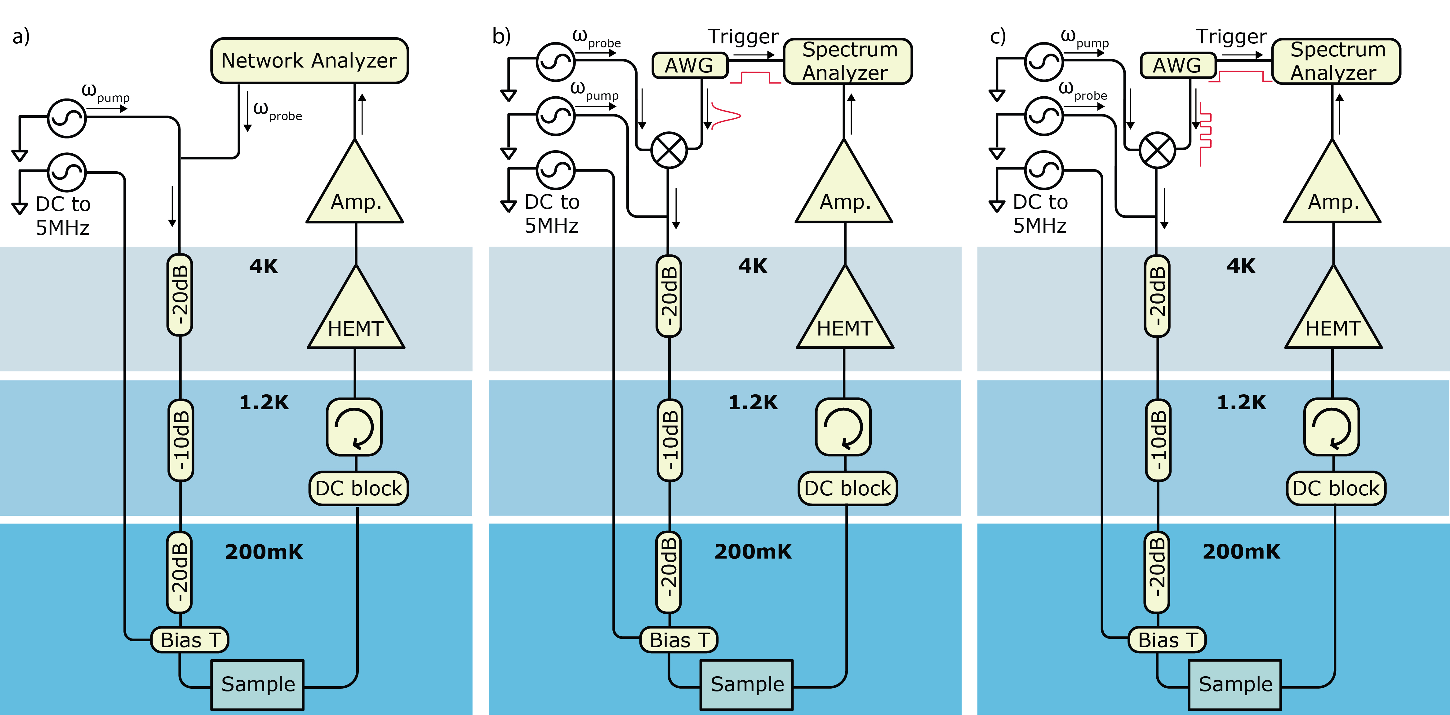
The experiments are carried out at cryogenic temperature around 200 mK in a dilution refridgerator. In the dilution refrigerator there are three signal lines: two coaxial-cable lines connecting the two ends of the sample feedline for the microwave input- and output-signal, and a low-frequency line to carry a drive signal (MHz) that enables resonant excitation of the nano-mechanical beam via Coulomb force. A sample of dimension 10 mm6 mm is mounted in a gold-plated copper box. SMA coaxial connectors are silver-glued to the coplanar wave guide (CPW) feedline at two ends, transmiting signals to/from the sample. Thermal noise from the tones at room temperature is suppressed using various attenuators at successive temperature stages, and by the attenuation of the coaxial cable. The DC-block filter (Minicircuits BLK-18 S+)) besides the sample prevents DC currents in the overall transmission loop. A high electron mobility transistor(HEMT) amplifier is anchored to 4 K and is isolated from the sample output by a circulator (Pamtech CTH 1392KS)).
For the OMIT measurement shown in Figure S2 a), a pump tone from a signal generator (R&S SMF 100A) and a probe tone from a network analyzer (R&S ZVA8) are coupled at room temperature and are transmitted down to the sample.
To experimentally explore the delay and advance of microwaves, as shown in Figure S2 b), a continuous-wave pump tone tuned to the red sideband () is sent from a signal generator (R&S SMF 100A) to the cavity. A weak probe tone tuned in resonance () with the cavity is generated from a second microwave source (R&S SMF 100A). The probe tone is amplitude-modulated by a Gaussian-shaped envelope generated with an arbitrary waveform generator (LeCroy arbstudio 1104D). The emission of this pulse triggers the acquisition of the transmitted probe field via an electronic spectrum analyzer (R&S FSV-30) in zero-span mode. The actual delay of the output pulse due to the OMIT is compared to the pulse output without a pump tone present.
To study the dynamics of OMIT, the pump tone generated from a signal generator(R&S SMF 100A) is tuned to the red sideband (), and switched by modulating its amplitude with rectangular pulses generated from an arbitrary wave generator (LeCroy arbstudio 1104D). The probe tone generated from an independent microwave source (R&S SMF 100A), tuned in resonance with the cavity (), is constantly on. An electronic spectrum analyzer in zero-span mode (R&S FSV-30) is triggered on with the first rectangular pulse, and the probe transmission is recorded.
IV Model for mechanical Duffing nonlinearity
In a frame rotation at the pump frequency, with , neglecting quantum noise and thermal noise terms, we have
| (6) |
| (7) |
| (8) |
where is the annihilation operators of the cavity mode, and are the position and momentum operators of the mechanical degree of freedom having effective mass and Duffing nonlinearity parameter , and is the drive amplitude normalized such that is the photon flux at the input of the cavity. In the steady state, all time derivative terms are zero, and the self-consistent static solutions for intra-cavity field and mechanical displacement are:
| (9) |
| (10) |
In order to solve the equations in the presence of the pump and probe fields , we use the ansatz , , and chose the phase reference of the cavity field so that is real and positive. Then we have
| (11) |
| (12) |
For a given , and a probe field of , we furthermore use the ansatz for the sideband fields of the pump (one of which is the probe):
| (13) |
| (14) |
| (15) |
Sorting the rotation terms, the relevant equations with are given by
| (16) |
| (17) |
| (18) |
In the resolved side band regime, the lower sideband is far off-resonance and is much smaller than , we therefore write and approximate . Here, the resolved-sideband regime is assumed (), as well as a large mechanical quality factor , so that the dynamic (resonant) response of the mechanical oscillator is much larger than the static displacement . Taking into account that , and using where , we have the pair of equations in the main article:
| (19) |
| (20) |
The transmission ratio of the probe field is given by:
| (21) |
An independent calibration measurement of the Duffing parameter is carried out by a direct mechanical driving through the low-frequency line coupled to the cavity via a bias-T. A vector networkanalyzer centered around the mechanical frequency probes over a 200 Hz wide spectrum. A probe tone of is sent simultaneously into the cavity with a frequency modulation at Hz and a modulation index of . The frequency modulation from the driven mechanical oscillation is calibrated with this injected frequency modulation, from the homodyne readout spectrum in Figure S3. The amplitude of the mechanical displacement is given by
| (22) |
From these measurements, the critical displacement and the Duffing parameter can be calculatedNayfeh1979 .
V Theory of Slowing microwave
The presence of the pump beam does not only induce a strong modification of the transmission of the probe field, and at the same time leads to a fast variation of the phase of the transmitted probe field across the transmission window
| (23) |
This can lead to significant group delays Schliesser2010 ; Weis2010 ; Safavi-Naeini2011 ; Jiang2011a , analog to that achieved with the electromagnetically induced transparancy in atomic Phillips2001 ; Liu2001 and in solid state media Longdell2005 .
| (24) |
In the case of red-detuned pumping () and , the group delay is approximated as,
| (25) |
assuming only the mechanical susceptibility contributes to the phase of the transmission spectrum (). Here denotes the optomechanical cooperativity parameter, and is cavity coupling parameter defined as the ratio of the cavity coupling rate to the cavity damping rate (. The maximum group delay is reached when
| (26) |
The maximum group delay is given by
| (27) |
when the cooperativity approaches .
In the case with a slightly detuned probe tone, , a good approximation of the group delay is given by
| (28) |
This equation allows the group delay to be negative, i.e. the advancing of the microwave waveforms, as long as the condition of is met.
The pulse delay is limited by the bandwidth of the transparency window ( ), as the medium becomes increasingly opaque at frequencies outside the transparency window, resulting in spreading of the pulse. In order to preserve the pulse, the Gaussian pulse bandwidth should be smaller than the bandwidth of the transmission window (). In the main test, we study the group delay of a pulse with a full-width-half-maximum (FWHM) duration of 83 ms, which satisfies this condition. To study the pulse distortion, a Gaussian pulse of 17 ms FWHM is sent to to cavity as a probe, and readout with a spectrum analyzer. As shown in Figure S4, the distortion reaches its maximum at the largest group delay.
VI Theory of dynamical switching of optomechanically induced transparency
We study the switching dynamics in a frame rotating at the pump frequency . We have the following set of ansatz
| (29) |
| (30) |
| (31) |
The intra-cavity field has a fast converge to its steady-state value (either or ) at a rate of . Applying the set of ansetz to equation (11)(12), and sort by rotation terms, the relevant equations with are
| (32) |
Note that we have assumed small excitation amplitudes so that the Duffing nonlinearity is negligible. Due to the low mechanical damping rate, we assume a the very slowing varying envelope of the displacement of the mechanical oscillator, , with . Further in the resolved-sideband regime, . The cavity field amplitude varies slowly as well, and therefore we have . The set of equations32) can then be simplified as
| (33) |
the solution of with detunning is approximately given by
| (34) |
Note the temporal dynamics of the amplitude is only determined by the temporal dynamics of the mechanical displacement amplitude . Using this solution in the equation of motion for , we have
| (35) |
Switch-on dynamics
Without loss of generality, we assume that at the time the pump tone is injected into the cavity and the initial mechanical oscillation amplitude , the solution of equation (35) has the form
| (36) |
where is its steady-state amplitude. Physically this means that rings up to its steady-state amplitude at a rate . The solution of is then given by
| (37) |
having the initial amplitude , and the steady state amplitude . This implies that theintra-cavity amplitude rings down at a rate close to and reaches its stead state amplitude . The readout of the transmitted field , therefore, rings up at a rate close to , as shown in Figure S5.
Switch-off dynamics
Moreover, when the pump field is switched off, the intra-cavity photon from the pump decays to at a fast rate of , resulting in a fast increase of the intra-cavity field to , corresponding to a fast decay of transmission amplitude shown in Fig.S5a) at . Due to the absence of the pump tone (=0), and further with , the mechanical oscillation amplitude (35) decays, in this case, as
| (38) |
A qualitative measure of this decay is given by the Raman-scattered field amplitude at the blue sideband of the cavity (i.e. ), to which the mechanical oscillation scatters part of the probe light even in absence of the pump. As is proportional to , the scattered field rings down at a rate of , as shown in Figure S5 b). The strong initial rise is associated with the fast rise of the intra-cavity probe amplitude to as the pump field is switched off.
References
- (1) Gorodetsky, M., Schliesser, A., Anetsberger, G., Deleglise, S., and Kippenberg, T. J. Optics Express 18, 23236–23246 (2010).
- (2) Ali H. Nayfeh, D. T. M. Nonlinear Oscillations. Wiley, (1979).
- (3) Schliesser, A. and Kippenberg, T. J. In Advances in atomic, molecular and optical physics, Arimondo, E., Berman, P., and Lin, C. C., editors, volume 58, chapter 5, 207–323. Elsevier Academic Press (2010).
- (4) Weis, S., Rivière, R., Deléglise, S., Gavartin, E., Arcizet, O., Schliesser, A., and Kippenberg, T. J. Science 330, 1520–1523 (2010).
- (5) Safavi-Naeini, A. H., Alegre, T. P. M., Chan, J., Eichenfield, M., Winger, M., Lin, Q., Hill, J. T., Chang, D. E., and Painter, O. Nature 472(7341), 69–73 April (2011).
- (6) Jiang, C., Chen, B., and Zhu, K. EPL (Europhysics Letters) 94(3), 38002 May (2011).
- (7) Phillips, D. F., Fleischhauer, A., Mair, A., Walsworth, R. L., and Lukin, M. D. Physical Review Letters 86, 783–786 (2001).
- (8) Liu, C., Dutton, Z., Behroozi, C., and Hau, L. Nature 409, 490–493 (2001).
- (9) Longdell, J. J., Fraval, E., Sellars, M. J., and Manson, N. B. Physical Review Letters 95(6), 063601 (2005).