Nonviscous motion of a slow particle in the dust crystal under microgravity conditions
Abstract
Subsonic motion of a large particle moving through the bulk of a dust crystal formed by negatively charged small particles is investigated using the PK-3 Plus laboratory onboard the International Space Station. Tracing the particle trajectories show that the large particle moves almost freely through the bulk of plasma crystal, while dust particles move along characteristic -shaped pathways near the large particle. In the hydrodynamic approximation, we develop a theory of nonviscous dust particles motion about a large particle and calculate particle trajectories. A good agreement with experiment validates our approach.
pacs:
52.27.Lw, 83.10.Rs, 82.70.DdI INTRODUCTION
Complex or dusty plasmas Morfill and Ivlev (2009); Fortov and Morfill (2009) are low temperature plasmas consisting of electrons, ions, neutral gas atoms, and charged microparticles or dust particles. Due to the higher electron mobility, these particles acquire large negative charges up to , where is the electron charge. Thus, the particle ensemble is a strongly coupled classical Coulomb system, in which plasma crystal, i.e., ordered structures of dust particles can be observed Thomas and Morfill (1996); Chu and I (1994); Thomas et al. (1994); Melzer et al. (1994); Hayashi (1999); Fortov et al. (2005). In experimental setups, dusty plasmas are usually studied in gas discharges at low pressures, e.g., in radio frequency (RF) discharges Thomas and Morfill (1996) or in striations of dc discharges Fortov et al. (2004a, 1996); Thomas, Jr. et al. (2007). In ground-based experiments, the electric field present in a discharge compensates the force of gravity and plays the role of a trap for dust particle structures. Three-dimensional structures obtained in RF and dc discharges are inhomogeneous ones. A large homogeneous bulk of dusty plasma, which almost fills the entire discharge volume, can be observed under microgravity conditions either in parabolic flights Morfill et al. (2006); Caliebe et al. (2011); Piel et al. (2008); Menzel et al. (2011); Arp et al. (2011) or onboard the International Space Station (ISS) Morfill et al. (2006); Schwabe et al. (2008); Morfill et al. (1999); Khrapak et al. (2011); Thomas et al. (2008); Schwabe et al. (2011).
Recently, self-excited dust–density waves caused by streaming ions were studied Menzel et al. (2011), and freezing and melting of dusty plasma upon variation of the neutral gas pressure was investigated Khrapak et al. (2011). The motion of a large particle inside the dust crystal of smaller particles was reported in Caliebe et al. (2011); Arp et al. (2011); Schwabe et al. (2011). It was demonstrated that supersonic motion is accompanied by the formation of the Mach cones, causing noticeable perturbation of plasma crystals. There were also relatively slow particles observed, moving with almost a constant velocity or even accelerating, which is incompatible with common notion of the interaction between the particle and dust crystal. Such particles appear to move freely, without long-range distortion of the ambient structure.
Using the PK-3 Plus laboratory onboard the ISS we have investigated motion of the dust particles in the vicinity of moving large particle. Such relatively slow particles are accelerated spontaneously on the outside of the particle cloud in RF discharge, penetrate into the dust cloud, and move inside it. We have made a series of snapshots of this motion in the plane of a laser sheet with a high-resolution camera, which allowed us to trace the trajectories of individual particles. Motion of small particles caused by the passage of a large particle has already been studied and used as a source of valuable information in the course of a ground-based experiment Fortov et al. (2004b), where heavy particles were dropped down to the cloud of dust particles levitating in the plasma sheath region of a RF capacitive planar discharge. Trajectories of particles suspended in low pressure glow discharges have also been studied in Chang et al. (2011). Dust particles were arranged in chains, and a heavy particle falling between neighboring dust chain bundles caused the elliptical motions of the background dust particles.
Superposition of successive frames recorded in our experiment reveals that many more dust particles in a close neighborhood of a moving particle circumscribe typical -shaped trajectories, while other particles remain almost at rest. We interpret this motion as a nonviscous flow about a large particle, for which we used a hydrodynamic approach. This approach is widely used as applied to the collective motion of dust particles Fortov and Morfill (2009); Nosenko and Goree (2004); Morfill et al. (2004); Ivlev et al. (2007). Based on classical solution for the velocity field Landau and Lifshits (1959), we integrate it to obtain streamline pathways for individual dust particles. A good agreement between recorded and calculated trajectories validates our basic assumption. Since a nonviscous motion is associated with zero momentum transfer, the force acting on a large particle vanishes in the idealized hydrodynamic model. If the particle interact only with the dust particles in its close neighborhood, as in the case of a nonviscous flow, the estimate of the direct particle–dust interaction force suggests that it is not greater than other major forces operating in low-pressure gas discharges (such as the ion drag and electric forces).
The paper is organized as follows. In Sec. II, we describe the experimental setup and results of tracing the dust particle motion caused by the passage of a large particle. A hydrodynamic approach is developed in Sec. III, where both numerical and analytical solutions for dust particle trajectories are obtained. Results are summarized in Sec. IV.
II EXPERIMENTAL SETUP AND RESULTS
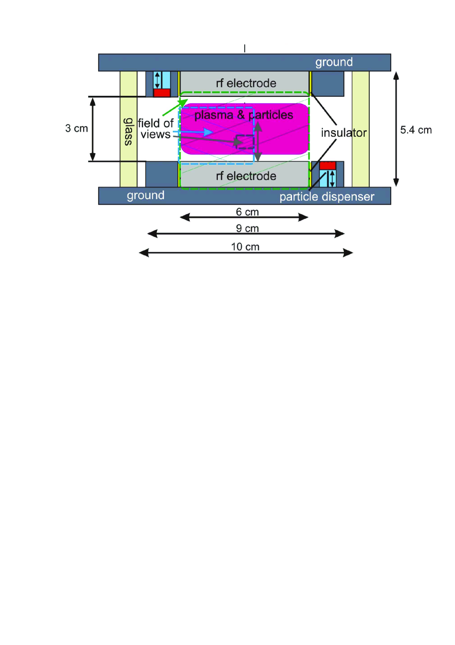
Here, we present an observation of a subsonic nonviscous motion of a large particle in the bulk of a three-dimensional complex plasma in the PK-3 Plus laboratory onboard the ISS. Details on the setup can be found in Thomas et al. (2008). The heart of this laboratory consists of a capacitively coupled plasma chamber with circular electrodes of 6 cm diameter and 3 cm apart (see Fig. 1). Microparticles can be injected into the main plasma with dispensers. The particles then form a cloud around the center of the chamber, typically with a central void caused by the ions streaming outwards. Generally, some larger particles are present in the chamber as well. The origin of these particles is not yet understood; these might be, for instance, agglomerates or larger particles left over from previous experiments (not removed during the cleaning procedure). They normally accumulate themselves at the periphery of the particle cloud, because of the dependence of the ratio of the electric and ion drag force on the particle diameter Goree et al. (1999). Sometimes, one of these larger particles gets sporadically accelerated and penetrates into the cloud – we shall term it projectile. The reason for such behavior remains a puzzle (for instance, it might be caused by a laser-induced rocket force Nosenko et al. (2010)). Nevertheless, these particles can be used as natural probes of the microparticle cloud Schweigert et al. (2002); Liu et al. (2003), in the same way as particles injected on purpose Caliebe et al. (2011); Arp et al. (2011); Buttenschön et al. (2011). Projectiles enable various active experiments to be performed in a wide range of testing parameters, thus providing the opportunity to reveal new features of strongly coupled complex plasmas. In particular, velocities of projectiles can vary significantly, and when they move through a cloud of background microparticles at supersonic velocities they excite Mach cones Schwabe et al. (2011). On the other hand, obvious disadvantages of experiments with projectiles is that their velocities cannot be controlled.
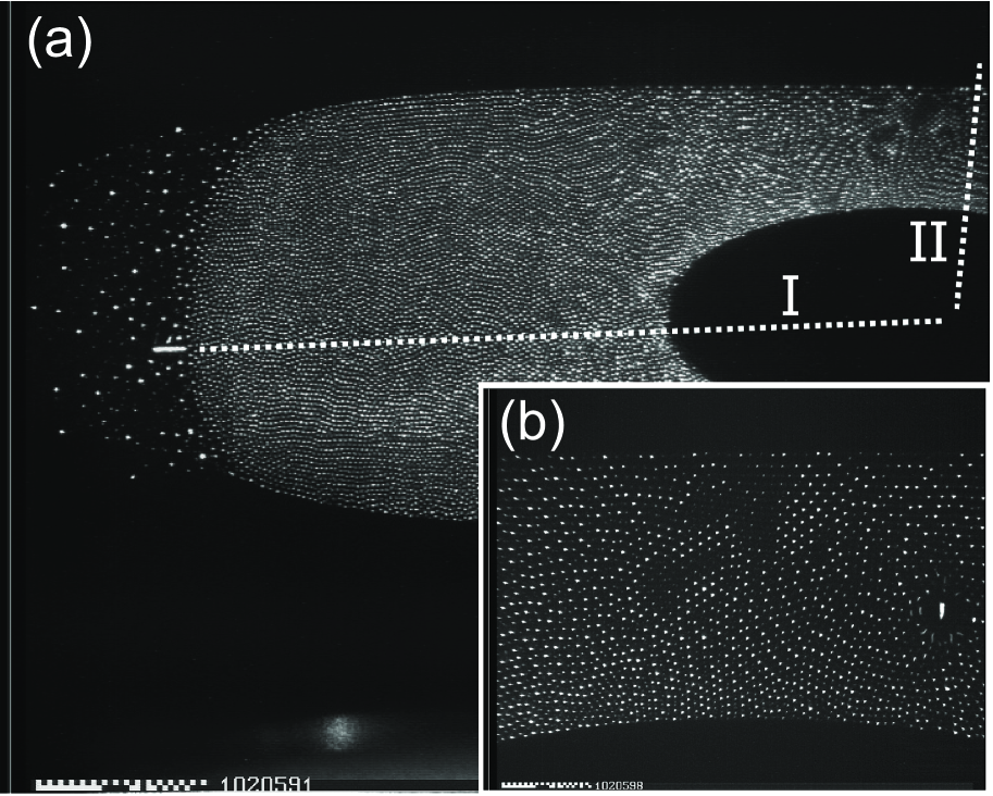
In what follows, we discuss in detail one example of a slow (subsonic) motion of a projectile. The experiment was performed during the 13th mission of PK-3 Plus on the ISS. Argon was used as buffer gas at a pressure of 10 Pa, and the main microparticle cloud was composed of melamine-formaldehyde particles with m diameter. The projectile was accelerated from the side and penetrated into the main cloud, moving almost horizontally from the left to the right (see Fig. 2a, phase I). To determine the size of the projectile, this experiment was compared with others performed with larger particles, which allowed us to conclude that the projectile radius was m. During its path towards the void, the velocity of the projectile varied, decreasing from 80 mm/s to 37 mm/s. Inside the void, the horizontal motion further slowed down. The particle was then accelerated upwards (see Fig. 2a, phase II), where it again penetrated into the microparticle cloud (see the discussion of microparticle trajectories in Ref. Schwabe et al. (2011)). In the region above the void, the particle was slower than before. It did, however, push the microparticles away to clear its path. Figure 2b shows the projectile motion during phase II. The microparticles that were pushed away moved in vortices around the probe particle. The projectile accelerated while traveling upwards through the microparticle cloud, so that its velocity increased from 7 to 14 mm/s. This value is still lower than the speed of sound.
In the experiments, we monitored the motion of dust particles in the vicinity of the projectile, by manually determining its position recorded by a high-resolution camera at 50 frames/s (a video frame is illustrated in Fig. 2b). The horizontal and vertical resolution of the camera was m per pixel and m per pixel, respectively.
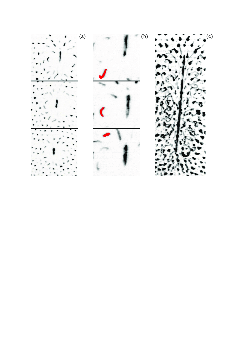
Experimental results on the motion of dust particles in the neighborhood of a slowly moving projectile are summarized in Fig. 3. The projectile motion from the void to chamber wall is represented by frames from bottom to top in Fig. 3a. Dust particles form a dust crystal, which can be represented as a set of the Wigner–Seitz cells around each particle. We estimate the dust particle number density as , hence the cell radius is cm. We can define the coupling parameter of interaction between the projectile and dust particles (or the scattering parameter) as the ratio of characteristic Coulomb energy at the plasma (ion) screening length (where and are the charges of the projectile and dust particle, respectively, in units of the electron charge ) to the kinetic energy of a dust particle in the reference frame co-moving with the projectile (where g is the dust particle mass and cm/s is the projectile velocity). Based on the analysis of recent melting experiments performed under identical conditions Khrapak et al. (2011), we estimate cm, and, assuming a linear scaling of charge with size, . This yields and, hence, the estimate for the radius of strong interaction between the projectile and dust particles gives Fortov et al. (2005) cm. This value turns out to be fairly close to the average distance between the projectile and nearest dust particle neighbors, cm (see Fig. 3a). Figure 3b shows successive phases of motion of an individual dust particle. Trajectories of such particles are revealed by frame superposition (Fig. 3c). It is evident that many more particles that interact with the projectile move along loops of similar form. The absence of loops in some regions can be accounted for by the following facts: first, the projectile trajectory is not exactly parallel to the laser illumination plane as well as dust crystal planes, so one can see only projections of dust particle trajectories. Second, visible pathways of the dust particles terminate at the points where particles go out of the laser sheet. Third, as the distance from the projectile increases, dust particles come at rest and become a part of the crystal. Upon such local crystallization, the particle can be pushed away from its initial trajectory.
III THEORY OF NONVISCOUS DUST PARTICLE MOTION
Let us first estimate the major forces acting on the projectile, in order to enlighten the physics of interaction between the projectile and the surrounding complex plasmas. We shall confine ourselves to treatment of the neutral drag force , the ion drag force , the electric force , and the force from dust particles .
We start the analysis with the neutral drag force, for which we can provide the most accurate estimate. This force is naturally pointed in the direction opposite to the projectile velocity. Assuming, as usual, diffuse scattering of neutrals from the particle surface (with full accommodation) we obtain Fortov et al. (2005)
where is the accommodation coefficient, cm-3 is the number density of neutral gas at the pressure of 10 Pa, g is the mass of argon atom, and cm/s is the thermal velocity of neutrals.
To estimate the plasma-induced forces, we need to know the magnitude of a dc electric field, . The field is generated due to ambipolar diffusion and can be deduced from the scaling Raizer (1991) , where cm is the distance between the RF electrodes (see Fig. 1) and eV is the electron temperature (here and in what follows, the temperature is expressed in the energy units). Then the electric force is
We note, however, that in dense clouds of dust particles, where the Havnes parameter is large, can be dramatically reduced (by an order of magnitude or even more, see Refs Land and Goedheer (2006); Sütterlin et al. (2009)). Therefore, the obtained value only be treated as a crude upper-bound estimate.
The ion drag force is determined by the ion drift velocity . Assuming the mobility-limited ion drift we get cm/s, where is the ion–neutral collision frequency, is the ion thermal velocity, and cm-2 is the ion–neutral collision cross section. The magnitude of the ion drag force is determined by the ion scattering parameter , which is of the order of 10 for our conditions. In this case, the force on the projectile is dominated by the direct ion collisions (absorption) and can be estimated from the following formula Fortov et al. (2005):
Here, we took into account that the ion drift velocity is of the order of the thermal velocity, and estimated the ion number density from the quasineutrality condition at large Havnes parameter, cm-3. Thus, and occur to be of the same order of magnitude. Note that the ion drag force, which always opposes the electric force, is pointed away from the center.
As regards the interaction between the projectile and dust particles, we assume that the Coulomb interaction is screened at short distances. Then the upper-bound estimate would suggest total transfer of the momentum from dust particles that find themselves inside this cylinder to the projectile. The force is given by Fortov et al. (2005)
which is not greater than the upper-bound estimates for the plasma-induced forces.
We conclude that the major known force acting on the projectile is the neutral drag which opposes the unknown driving force and, presumably, results in the observed (locally) steady-state motion (the neutral damping rate is s-1, i.e., the transition to steady state occurs within s). Leaving the discussion of possible driving mechanisms aside, let us focus on the flow of dust particles caused by the projectile. We assume that the plasma crystal is melted in the neighborhood of the projectile that is streamlined by dust particles. If the stream flow is a potential nonviscous one the total momentum is conserved, and must vanish. This assumption can be validated by comparison between dust particle trajectories calculated theoretically and those obtained from experiment.
We apply a hydrodynamic approach to describe the dust particle motion, which is widely used in physics of complex and dusty plasmas Fortov and Morfill (2009). Based on the discussion above, we can treat the projectile–dust interaction as that of hard spheres characterized by the length scale . Consider a steady flow of an incompressible liquid of dust particles, described by the Navier–Stokes equation,
| (1) |
where is the velocity field, and are the pressure and density, respectively, and is the shear viscosity of the particle fluid. For an incompressible fluid, when const, Eq. (1) is completed by the continuity equation
| (2) |
Let us estimate the relevant Reynolds number, , which characterizes the relative importance of the viscous term in Eq. (1). Using results of the molecular dynamics simulations of Yukawa fluids Saigo and Hamaguchi (2002), we obtain that for our conditions the kinematic viscosity can be estimated as , where s-1 is the dust plasma frequency, so that the Reynolds number is . Thus, we can reasonably neglect the viscosity and thus reduce Eq. (1) to the Euler equation for an ideal fluid,
| (3) |
For an irrotational flow of incompressible liquid (), the substitution transforms (2) to the form
| (4) |
where is the velocity field potential.
Consider a streamline about a sphere with the radius moving with a constant velocity . The boundary conditions are and , where is the radius vector from the center of the sphere and is the radial unit vector. The unique solution of Eq. (4) with these boundary conditions is , so that Landau and Lifshits (1959)
| (5) |
The pressure field can be derived from Eq. (3) but it is unnecessary for our purposes.
The streamlines can be obtained by integration of Eq. (5) in the laboratory frame of reference. Let the -axis be directed along the motion of a sphere. Then vector has the components , where and . We introduce the variables , , and , where , to rewrite Eq. (5) as a set of differential equations,
| (6) |
with the initial conditions and (). Due to the axial symmetry, the third equation for -axis coincides with the second equation (6) and is therefore redundant.
Because the decay of particle velocity (5) with the distance from projectile is rather fast, , we can assume that particles move in a thin fluid tube in the vicinity of a sphere with the radius so that the difference between and can be neglected and Equations (6) are then reduced to
| (7) |
with the initial conditions and . Within the framework of this approximation, we have to assume also that a particle is quiescent until it finds itself on the surface of a moving sphere (projectile cell). This instant corresponds to the time and to the distance between the particle and direction of projectile motion (impact parameter). Obviously, solution of Eqs. (6) obeys the condition . Due to the time reversibility of Eqs. (7), the particle must stop at and further remain quiescent, the total time of motion being . Thus, the initial conditions should be completed by the ‘collision’ condition , where the sign of defines the direction of particle motion. We integrate Eqs. (7) to derive and . In conventional units, we obtain
| (8) |
From the second equation (8) we obtain
| (9) |
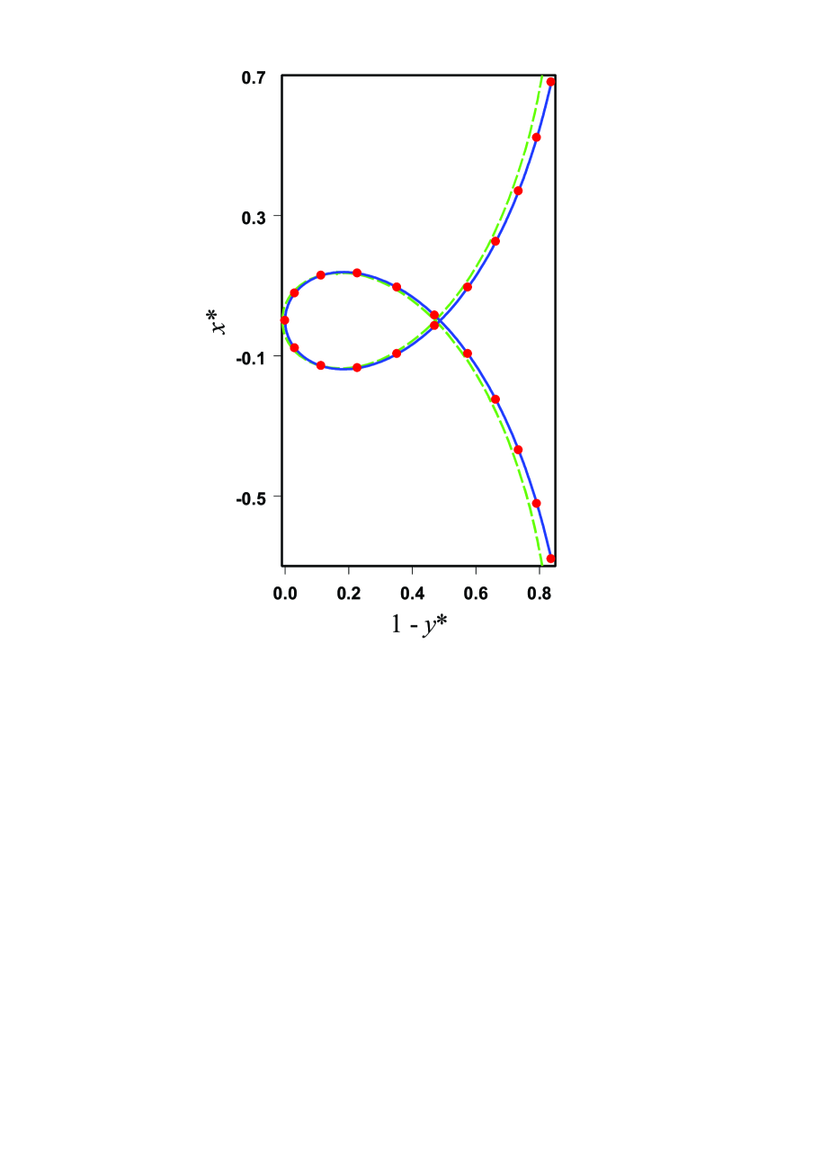
If , we find approximately for a grazing collision. At , we have . Streamline (8) is shown in Fig. 4 for , which corresponds to in the framework of used approximation. It is seen in Fig. 4 that the approximate solution almost coincides with the numerical solution of equation set (6) corresponding to the same . Our approximation is valid even at a large impact parameter because in this case, numerical solution of (6) yields , i.e., the distance between the particle and projectile is still not much different from . Figure 5 shows a good correspondence between solution (8), (9) and experimentally observed traces of individual particles extracted from Fig. 3c in their closed portions. Indication of this correspondence is a good agreement between the ratio of the height of a closed loop to determined experimentally (Figs. 3c and 5), which amounts to about , while the theoretical value is (cf. Fig. 4). This ratio is independent of the loop position relative to the projectile path. Note that since the streamline takes place in a close neighborhood of the projectile and farther regions are crystallized, an approximate solution (8), (9) utilizing the same approximation seems to be even more adequate to treated system than the numerical solution. Open portions of particle traces reveal some differences from theory. In Fig. 5, the upper trace portion of the bottom loop on the left-hand side seems to disappear due to the fact that the particle go out of the illumination plane. On the contrary, the upper trace portion of the top loop on the left-hand side would not appear at all but the particle was probably pushed towards the projectile due to spatial re-distribution of particles in the course of local crystallization.
We have demonstrated that the stream flow of dust particles is almost a potential nonviscous one. In an ideal model, the momentum transferred from dust particles to projectile and back must coincide, so that the force of interaction between the dust particles and projectile vanishes. In reality, however, is never equal to zero. It follows from solutions for the particle trajectories obtained above that the motion of particles outside the cylinder (whose axis coincides with the projectile trajectory) can be disregarded, as we originally assumed. The lower-bound estimate stems from the momentum not transferred back to the projectile, due to collisions between neutrals and dust particles moving along the loops with the velocity estimated as :
where cm is the dust particle radius. Thus, proves to be of the same order of magnitude as its upper-bound estimate obtained above and as . However, if treated damping effect was taken into account in Eq. (1) the solution for trajectories (8), (9) would not change because it is a consequence of unchanged Eq. (2) with the same boundary conditions.
IV CONCLUSION
In this study, we have observed that a heavy particle (projectile) going through the dust crystal with a relatively low (subsonic) velocity appears to move almost freely. We have proposed a new explanation of this fact implying a nonviscous flow of the dust particles about the projectile, in which the force of interaction between the projectile and dust particles vanishes. To prove this, we monitored the particle dynamics by means of a high-resolution camera. Superposition of successive frames revealed typical -shaped pathways of dust particles in the neighborhood of projectile. Since the system is strongly coupled, it can be divided into the Wigner–Seitz cells around each particle including the projectile, whose motion does not break close ordering. However, the projectile melts the crystal in its neighborhood, and the dust particles flow about the projectile cell boundary in such a way that the distance between individual dust particles and the projectile, which can be measured using recorded frames, is the sum of radii of the Wigner–Seitz cells around dust particles and the projectile. In the framework of our model, we have to imply that the cells around particles rather than the particles themselves take part in the interaction. In the absence of direct interparticle contacts, the shear viscosity must vanish and we can consider the nonviscous flow of the cells.
The classical solution for the velocity field in a potential nonviscous flow about a sphere moving with a constant velocity can be regarded as a set of differential equations for the trajectories of individual dust particles. We have solved these equations numerically and obtained an analytical solution, which approximates closely the numerical one. This solution, which defines the coordinates of dust particles as explicit functions of time, is in a good agreement with particle trajectories obtained experimentally by superposition of successive frames. This supports our main assumption concerning the nonviscous nature of particle flow. Because such motion implies no momentum transfer from liquid to the projectile, the drag force arising from the interaction between the projectile and dust particles must vanish. Note that examples of such type of dust particle collective motion were previously not encountered in physics of complex and dusty plasmas.
A real system does not show idealized behavior. Not all the particles move along the -shaped pathways, which we attribute (i) to the fact that the illumination plane does not coincides with one of the crystalline planes and is not exactly parallel to the direction of the projectile motion, (ii) to the finite thickness of the laser sheet, so that particles can leave the illuminated space, and (iii) to a local crystallization after the projectile passage. In addition, the force of interaction between the projectile and dust particles does not vanish exactly. However, a general conclusion of the developed theory, that only the dust particles inside a cylinder with the radius are involved in collective motion, is strongly confirmed by Fig. 3a. Note that this is a consequence of the boundary condition imposed on the projectile cell, which implies a nonzero tangential velocity field component. In the case of a viscous flow (e.g., Refs Nosenko and Goree (2004); Ivlev et al. (2007)) the situation can be different due to vanishing of this component, resulting to much larger number of moving particles.
We can conclude that a large particle can move almost freely inside the bulk of a strongly coupled dust crystal. Our investigation also points to the fact that a hydrodynamic approach can be valid at small length scales down to several interparticle distances. The processes of local dust crystal melting and freezing, which were not treated in detail in the present study, will be addressed in future work.
Acknowledgements.
The microgravity research is supported by the space agency of the Deutsches Zentrum für Luft- und Raumfahrt e.V., with funds from the federalministry for economy and technology according to a resolution of the Deutscher Bundestag under grant No. 50WP0203 and 50WM1203. We additionally acknowledge financial support from the European Research Council under the European Union’s Seventh Framework Programme (FP7/2007-2013) / ERC Grant agreement 267499, and from the Russian Basic Research Foundation and ROSCOSMOS. We like to thank the industry teams from RSC-Energia and Kayser-Threde and the cosmonauts who turned the ambitious research on the ISS into a success.References
- Morfill and Ivlev (2009) G. E. Morfill and A. V. Ivlev, Rev. Mod. Phys. 81, 1353 (2009).
- Fortov and Morfill (2009) V. E. Fortov and G. E. Morfill, eds., Complex and Dusty Plasmas: From Laboratory to Space, Series in Plasma Physics (CRC Press, New York, 2009).
- Thomas and Morfill (1996) H. M. Thomas and G. E. Morfill, Nature 379, 806 (1996).
- Chu and I (1994) J. H. Chu and L. I, Phys. Rev. Lett. 72, 4009 (1994).
- Thomas et al. (1994) H. Thomas, G. E. Morfill, V. Demmel, J. Goree, B. Feuerbacher, and D. Möhlmann, Phys. Rev. Lett. 73, 652 (1994).
- Melzer et al. (1994) A. Melzer, T. Trottenberg, and A. Piel, Phys. Lett. 191, 301 (1994).
- Hayashi (1999) Y. Hayashi, Phys. Rev. Lett. 83, 4764 (1999).
- Fortov et al. (2005) V. Fortov, A. Ivlev, S. Khrapak, A. Khrapak, and G. Morfill, Phys. Rep. 421, 1 (2005).
- Fortov et al. (2004a) V. E. Fortov, A. G. Khrapak, S. A. Khrapak, V. I. Molotkov, and O. F. Petrov, Phys.-Usp. 47, 447 (2004a).
- Fortov et al. (1996) V. E. Fortov, A. P. Nefedov, V. M. Torchinskii, V. I. Molotkov, A. G. Khrapak, O. F. Petrov, and K. F. Volykhin, JETP Lett. 64, 92 (1996).
- Thomas, Jr. et al. (2007) E. Thomas, Jr., R. Fisher, and R. L. Merlino, Phys. Plasmas 14, 123701 (2007).
- Morfill et al. (2006) G. E. Morfill, U. Konopka, M. Kretschmer, M. Rubin-Zuzic, H. M. Thomas, S. K. Zhdanov, and V. Tsytovich, New J. Phys. 8, 7 (2006).
- Caliebe et al. (2011) D. Caliebe, O. Arp, and A. Piel, Phys. of Plasmas 18, 073702 (2011).
- Piel et al. (2008) A. Piel, O. Arp, M. Klindworth, and A. Melzer, Phys. Rev. E 77, 026407 (2008).
- Menzel et al. (2011) K. O. Menzel, O. Arp, and A. Piel, Phys. Rev. E 83, 016402 (2011).
- Arp et al. (2011) O. Arp, D. Caliebe, and A. Piel, Phys. Rev. E 83, 066404 (2011).
- Schwabe et al. (2008) M. Schwabe, S. K. Zhdanov, H. M. Thomas, A. V. Ivlev, M. Rubin-Zuzic, G. E. Morfill, V. I. Molotkov, A. M. Lipaev, V. E. Fortov, and T. Reiter, New J. Phys. 10, 033037 (2008).
- Morfill et al. (1999) G. E. Morfill, H. M. Thomas, U. Konopka, H. Rothermel, M. Zuzic, A. Ivlev, and J. Goree, Phys. Rev. Lett. 83, 1598 (1999).
- Khrapak et al. (2011) S. A. Khrapak, B. A. Klumov, P. Huber, V. I. Molotkov, A. M. Lipaev, V. N. Naumkin, H. M. Thomas, A. V. Ivlev, G. E. Morfill, O. F. Petrov, V. E. Fortov, Y. Malentschenko, and S. Volkov, Phys. Rev. Lett. 106, 205001 (2011).
- Thomas et al. (2008) H. M. Thomas, G. E. Morfill, V. E. Fortov, A. V. Ivlev, V. I. Molotkov, A. M. Lipaev, T. Hagl, H. Rothermel, S. A. Khrapak, R. K. Suetterlin, M. Rubin-Zuzic, O. F. Petrov, V. I. Tokarev, and S. K. Krikalev, New J. Phys. 10, 033036 (2008).
- Schwabe et al. (2011) M. Schwabe, K. Jiang, S. Zhdanov, T. Hagl, P. Huber, A. V. Ivlev, A. M. Lipaev, V. I. Molotkov, V. N. Naumkin, K. R. Süutterlin, H. M. Thomas, V. E. Fortov, G. E. Morfill, A. Skvortsov, and S. Volkov, EPL 96, 55001 (2011).
- Fortov et al. (2004b) V. E. Fortov, O. F. Petrov, A. D. Usachev, and A. V. Zobnin, Phys. Rev. E 70, 046415 (2004b).
- Chang et al. (2011) M.-C. Chang, Y.-P. Tseng, and L. I, Phys. of Plasmas 18, 033704 (2011).
- Nosenko and Goree (2004) V. Nosenko and J. Goree, Phys. Rev. Lett. 93, 155004 (2004).
- Morfill et al. (2004) G. E. Morfill, M. Rubin-Zuzic, H. Rothermel, A. V. Ivlev, B. A. Klumov, H. M. Thomas, U. Konopka, and V. Steinberg, Phys. Rev. Lett. 92, 175004 (2004).
- Ivlev et al. (2007) A. V. Ivlev, V. Steinberg, R. Kompaneets, H. Höfner, I. Sidorenko, and G. E. Morfill, Phys. Rev. Lett. 98, 145003 (2007).
- Landau and Lifshits (1959) L. D. Landau and E. M. Lifshits, Fluid Mechanics (Pergamon Press, 1959).
- Goree et al. (1999) J. Goree, G. E. Morfill, V. N. Tsytovich, and S. V. Vladimirov, Phys. Rev. E 59, 7055 (1999).
- Nosenko et al. (2010) V. Nosenko, A. V. Ivlev, and G. E. Morfill, Phys. Plasmas 17, 123705 (2010).
- Schweigert et al. (2002) V. A. Schweigert, I. V. Schweigert, V. Nosenko, and J. Goree, Phys. Plasmas 9, 4465 (2002).
- Liu et al. (2003) B. Liu, J. Goree, V. Nosenko, and L. Boufendi, Phys. Plasmas 10, 9 (2003).
- Buttenschön et al. (2011) B. Buttenschön, M. Himpel, and A. Melzer, New J. Phys. 13, 023042 (2011).
- Raizer (1991) Y. P. Raizer, Gas Discharge Physics (Springer, Berlin, 1991).
- Land and Goedheer (2006) V. Land and W. J. Goedheer, New J. Phys. 8, 8 (2006).
- Sütterlin et al. (2009) K. R. Sütterlin, A. Wysocki, A. V. Ivlev, C. Räth, H. M. Thomas, M. Rubin-Zuzic, W. J. Goedheer, V. E. Fortov, A. M. Lipaev, V. I. Molotkov, O. F. Petrov, G. E. Morfill, and H. Löwen, Phys. Rev. Lett. 102, 085003 (2009).
- Saigo and Hamaguchi (2002) T. Saigo and S. Hamaguchi, Phys. Plasmas 9, 1210 (2002).
FIGURE CAPTIONS
Fig. 1: The cross-sectional schematic of the plasma chamber
Fig. 2: (a), snapshot of the microparticle cloud from quadrant view camera (field of view is 35.7 mm x 26.0 mm). On the left-hand side, a small track of initial movement of the probe particle (projectile) into the cloud is visible. The horizontal dashed line arrow shows schematically the path of projectile on the left-hand side (phase I); the vertical dashed line arrow, the path of projectile from the void into the upper part of microparticle cloud (phase II). (b), snapshot of the microparticle cloud from high-resolution view camera (field of view is 8.1 mm x 5.9 mm). A small track on the right-hand side shows the projectile motion in phase II
Fig. 3: Recorded positions of dust particles and the projectile (negative images). Time interval between individual frames is (a), 0.1 s and (b), 0.02 s; (c) is a superposition of 12 frames with the time interval of 0.02 s. The projectile motion from void to chamber wall corresponds to frames from bottom to top
Fig. 4: Calculated trajectory of a dust particle moving about the projectile for . Solid line shows calculation using (8), (9) and dashed line, numerical integration of Eqs. (6) for the same . Dots mark the intervals
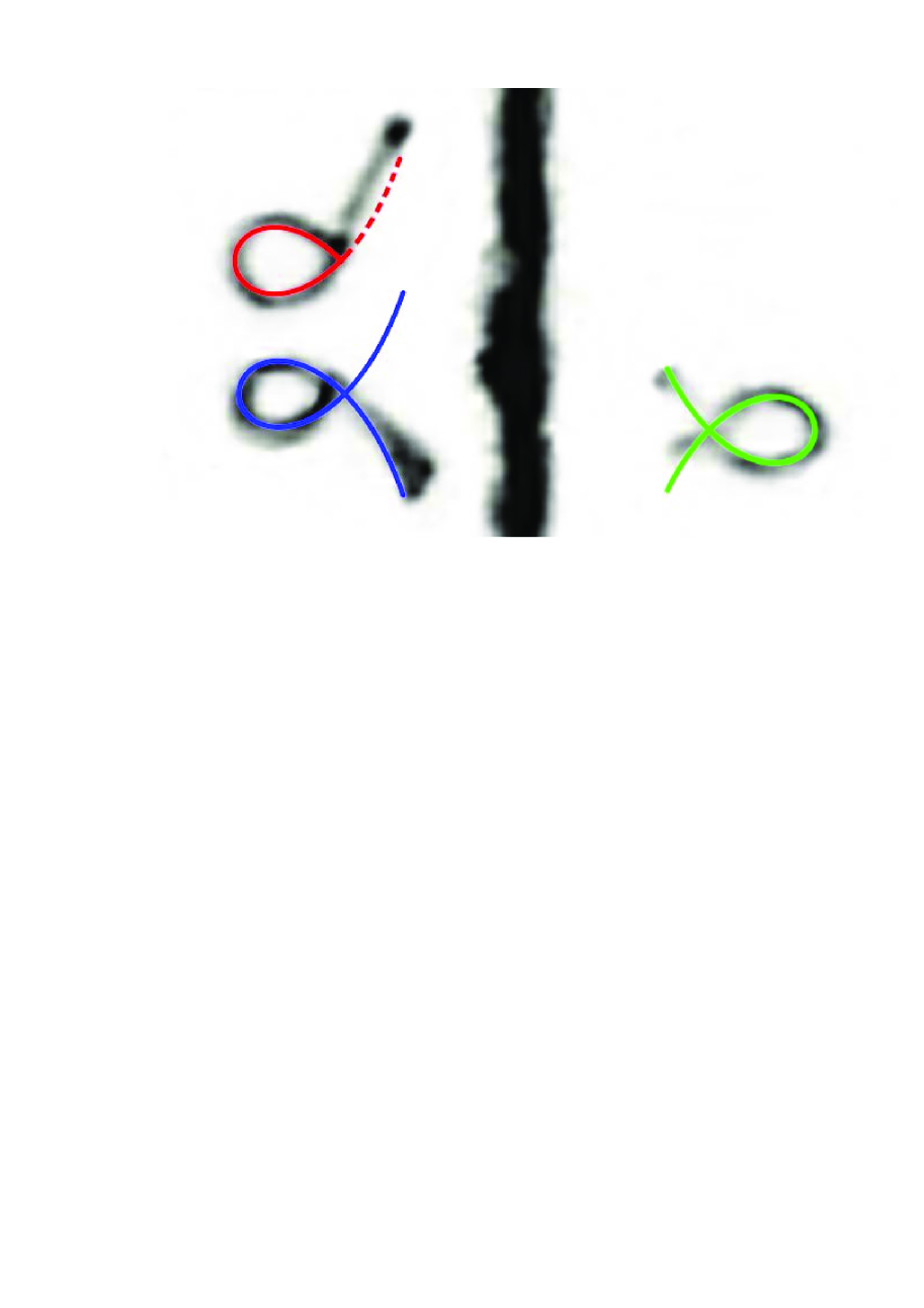
Fig. 5: Individual dust particles moving along the -shaped pathways. Traces are the superposition of frames obtained in the experiment (negative image, vertical trace marks the projectile trajectory), solid lines show calculation by formulas (8) and (9), dashed line indicates the trajectory portion ‘forced’ by local crystallization