Ion irradiation tolerance of graphene as studied by atomistic simulations
Abstract
As impermeable to gas molecules and at the same time transparent to high-energy ions, graphene has been suggested as a window material for separating a high-vacuum ion beam system from targets kept at ambient conditions. However, accumulation of irradiation-induced damage in the graphene membrane may give rise to its mechanical failure. Using atomistic simulations, we demonstrate that irradiated graphene even with a high vacancy concentration does not show signs of such instability, indicating a considerable robustness of graphene windows. We further show that upper and lower estimates for the irradiation damage in graphene can be set using a simple model.
Since the isolation of graphene in 2004 Novoselov2004 , a multitude of applications have been proposed for this one-atom-thick carbon membrane Geim2009a . Although graphene is probably best known for its unique electronic properties CastroNeto2009 , it is also the strongest material ever measured Lee2008 . Moreover, on the one hand, even a single layer of graphene can withstand pressure imposed by a macroscopic amount of gas Stolyarova2009 , and does not allow even the smallest atmospheric molecules to permeate Bunch2008 . On the other hand, porous graphene has been considered to be the ultimate membrane for gas separation Jiang2009c and an ideal material for supercapasitors Zhu2011a . At the same time, graphene is virtually transparent to high energy ions, which pass through the material without creating substantial damage due to negligible interaction cross section Lehtinen2010b . Due to the unique combination of strength and impermeability to gases, graphene can be used as a window material in external ion beam experiments with samples which cannot be put into vacuum required for the operation of the ion-beam system Lehtinen2010b , replacing silicon-nitride membranes Dran2004 currently used for this purpose. Very recently, a similar technology has been demonstrated with graphene oxide windows for in situ environmental cell photoelectron spectroscopy Kolmakov2011 .
Nevertheless, irradiation damage can accumulate with increasing ion dose, so that the operation of graphene as an ion-transparent but gas-separating membrane depends crucially on its ability to withstand continuous irradiation during the experiment. Although the ion irradiation response of graphene has been recently studied both experimentally Tapaszto2008 ; Chen2009 ; Compagnini2009 ; Giannazzo2009 ; Zhou2010a ; Mathew2011 ; Ney2011 ; Mathew2011a ; Compagnini2011 ; Chen2011 ; Diaz-Pinto2011 ; Buchowicz2011 ; Cancado2011 ; Ugeda2011 ; Ugeda2012 and theoretically Lehtinen2010b ; Ahlgren2011 ; Lehtinen2011b , the atomic-scale details of damage accumulation during continuous exposure to the ion beam remain unknown. In the experiments, ion doses were either very low creating only spatially well-separated defects or so high that graphene was completely destroyed, and it was not possible to get any insight into damage accumulation process. Similarly, the theoretical work has hitherto concentrated on the effects of individual ion impacts on pristine graphene. Continuous high-dose irradiation has been taken into account only in a stochastic manner disregarding the actual dynamics of consecutive ion impacts on a defective graphene structure Lehtinen2011b .
In this Letter, we utilize atomistic simulations to study the effects of ion irradiation on graphene with defects to understand the details of damage accumulation. We demonstrate that irradiated graphene with vacancy concentration of at least 35% does not show any signs of structural failure, pointing to considerable stability of graphene windows in ion beam experiments. Our results can be directly utilized both in estimating the wear of graphene windows used to separate ion beam systems from volatile targets as well as in designing optimum parameters for carving nanopores into graphene membranes using a focused ion beam.
We created our graphene target structures by randomly removing atoms from the pristine lattice, then running a 3 ps annealing simulation at 800 K to allow saturation of open bonds where possible, and finally relaxing the structure to its local energy minimum by quenching to 0 K. At this point we also removed all isolated fragments leaving only the largest continuous atomic network to be used as a target for our ion irradiation simulations, as illustrated in Fig. 1. The initial structure consisted of 1250 carbon atoms. We performed in total 200,000 irradiation simulations for individually created structures with impact points randomly selected in the middle of the simulation cell. For each structure, ion species (He, Ar, Xe), ion energy () and initial vacancy concentration () combination, we performed on average more than 1050 independent simulations in order to collect representative statistics.
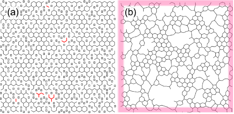
Irradiation simulations were carried out using the molecular dynamics (MD) method as implemented in the parcas simulation code Nordlund1998a . The carbon-carbon interaction was described by the reactive bond-order potential developed by Brenner et al. Brenner1990b ; Brenner1992 , disregarding the bond conjugation term which is not important for ion irradiation effects Krasheninnikov2001 . The interactions between noble gas ions 111We refer to the projectile as ion throughout the text although the charge of the impinging particle is not explicitly taken into account in our simulation setup. and carbon atoms were modeled by the universal repulsive potential by Ziegler, Biersack and Littmark Ziegler1985 . A similar repulsive potential was fitted to the carbon-carbon interaction at short distances in order to properly describe high energy collisions between carbon atoms. A few atomic rows at the edges of the periodic directions were coupled to the Berendsen thermostat Berendsen1984 kept at 0 K in order to model the dissipation of heat from the irradiated area, as indicated in Fig. 1b. We have previously used a similar simulation setup for modeling ion irradiation of carbon nanotubes Tolvanen2007a ; Krasheninnikov2002b , pristine graphene Lehtinen2010b ; Ahlgren2011 and hexagonal boron nitride mono-layers Lehtinen2011 . After each ion impact we again quenched the system into a local energy minimum for analysis.
In Fig. 2 we present sputtering yield () for different ions and irradiation energies as a function of . Note that in the limit , the results approach those for pristine graphene Lehtinen2010b , as expected. Despite the fact that the presented results are averaged over a large number of simulations, significant statistical variations remain present in the data. However, the qualitative behavior of as a function of vacancy concentration is nevertheless apparent. For instance, it is clear that tends to decrease with increasing due to increased probability for the ion to pass through an existing vacancy with an energy-dependent slope until the highest considered vacancy concentrations (%). Perhaps the most surprising result is the continuity of all of the curves (except for some statistical fluctuations), since one could assume that at some point the defective membrane would become structurally unstable so that it would break showing an abrupt increase in the sputtering yield (corresponding to a lost membrane). Our results show that such an instability point is not reached within any reasonable vacancy concentration. Indeed, a careful analysis of the distribution of the number of sputtered atoms as a function of shows no abrupt changes in the relative probabilities for sputtering smaller or larger numbers of atoms at once. The structural stability of the membranes was further checked by 1 ns anneal simulations at 1500 K for 150 structures with different after the analysis. No apparent instabilities, e.g., disintegration or crumpling, were observed. We also point out that although mechanical properties of perforated graphene are inferior as compared to the pristine material, the fracture stress remains as high as GPa corresponding to nearly 10% strain for graphene with up to 2 nm holes Khare2007 .
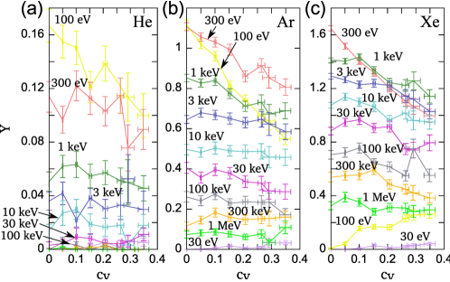
An additional surprise is the clearly evident ion energy-dependent slope of the data presented in Fig. 2. Based purely on geometrical arguments, should decrease with due to a drop in target density and thus smaller collision cross section as
| (1) |
where corresponds to pristine graphene. Since this equation does not depend on the energy of the impinging ion, it is clear that it cannot completely describe the data shown in Fig. 2. Therefore, to quantify the differences between the data and the geometric model, we introduced a new dimensionless variable in Eq. 1 to obtain
| (2) |
Fitting the data presented in Fig. 2 to Eq. 2 allows us to systematically analyze the deviation from the geometric model as a function of ion energy. The results of the fits are presented in Fig. 3. Naturally, the fitted sputtering yield at zero vacancy concentration () for each energy/ion combination (Fig. 3a) is nearly identical to the simulation data for pristine graphene Lehtinen2010b . The modified equation reduces to the simple geometric model (Eq. 1) for , whereas negative values indicate increasing for increasing (a positive slope), and would suggest sputtering yield which does not depend on .
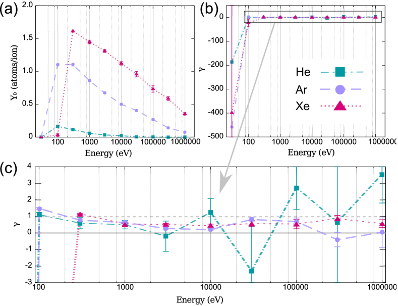
As evident from Fig. 3(b), is negative at low ion energies. In the case of He and Ar, this occurs only up to eV, whereas for the heaviest Xe also the 100 eV data has a positive slope. For energies immediately above these, indicating a perfect agreement with the simple geometric model. Then, decreases until an apparent saturation towards a constant value (within our statistical accuracy) at an ion-dependent energy. At the saturation the average values of are , and for He, Ar and Xe, respectively (notice that the statistical uncertainty decreases for increasing ion mass).
The varying values of can be understood taking into account how the collision process changes with increasing ion momentum (and thus energy) Lehtinen2010b . At low energies, the collision cross section is large, and the collision process is relatively slow. The pre-existing vacancies in the structure on average lower the binding energy of the target atoms which makes an important contribution to the sputtering when the transferred energies are very close to the displacement threshold (22 eV in pristine graphene Kotakoski2010 ; Meyer2012 and somewhat lower for under-coordinated atoms Kotakoski2011b ). As our data shows, this effect is large enough to overcome the effect of the lowered target density at the lowest ion energies. While ion energy increases, a larger fraction of the recoil atoms will receive – during the collision – energies clearly higher than the threshold. Therefore, the weaker binding is not significant anymore, and the data agrees better with the simple geometric model. However, at even higher energies the collision cross section is very small and the time during which the ion interacts with the target atoms is very short. This means that the target atom will remain essentially immobile during the interaction, which correspondingly becomes symmetric over the graphene plane. Therefore, the transferred momentum will almost completely be in the in-plane direction. In this case the role of the target density is negligible after the initial impact, since the displaced target atom will travel in the in-plane direction as long as it takes to collide with another target atom. While the overall binding of the defective membrane is lowered, these secondary collisions can displace more atoms from the structure than what would happen in the case of a pristine target. This sets also for the highest irradiation energies, as can be seen in Fig. 3c. Thus, for energies keV, the modified geometric model can be used to set the upper and lower bounds for irradiation-induced damage in graphene.
We stress that defective graphene layers with relatively large defects are still hardly permeable Leenaerts2008 for small atoms and molecules. Moreover, vacancies in graphene tend to partially “heal” themselves by forming non-hexagonal rings due to bond rotations Lee2005b ; Kotakoski2011a ; Kotakoski2011 ; Meyer2012 . As ion beam can give rise to dissociation of atmospheric molecules, passivation of dangling bonds by hydrogen atoms or incorporation of foreign atoms (e.g., nitrogen Meyer2011 ) as substitutional impurities should also decrease the permeability of graphene membranes.
In conclusion, we have shown that the response of graphene to ion irradiation remains consistent to remarkably high vacancy concentrations (up to 35%). Although the damaging process varies with the mass of the impinging ion as well as its energy, we never observed sudden breakage of the membrane indicating severe structural instabilities with respect to the ion irradiation. Naturally, whether the mechanical stability of a perforated graphene membrane is high enough for a particular application depends on the actual experimental conditions. However, taking this into account, our results can be used to predict the effects of ion irradiation on the membrane during the experiment using the presented simple geometric model in order to estimate the usability of graphene windows. Our results can also be used to design optimal conditions for carving nanopores into graphene using a focused ion beam.
The authors acknowledge financial support by the University of Helsinki Funds and the Academy of Finland as well as generous grants of computer time provided by CSC Finland.
References
- (1) K. S. Novoselov, A. K. Geim, S. V. Morozov, D. Jiang, Y. Zhang, S. V. Dubonos, I. V. Grigorieva, and A. A. Firsov, Science 306, 666 (2004).
- (2) A. K. Geim, Science 324, 1530 (2009).
- (3) A. Castro Neto, F. Guinea, N. Peres, K. Novoselov, and A. Geim, Rev. Mod. Phys. 81, 109 (2009).
- (4) C. Lee, X. Wei, J. W. Kysar, and J. Hone, Science (New York, N.Y.) 321, 385 (2008).
- (5) E. Stolyarova, D. Stolyarov, K. Bolotin, S. Ryu, L. Liu, K. T. Rim, M. Klima, M. Hybertsen, I. Pogorelsky, I. Pavlishin, et al., Nano Lett. 9, 332 (2009).
- (6) J. S. Bunch, S. S. Verbridge, J. S. Alden, A. M. van der Zande, J. M. Parpia, H. G. Craighead, and P. L. McEuen, Nano Lett. 8, 2458 (2008).
- (7) D.-E. Jiang, V. R. Cooper, and S. Dai, Nano Lett. 9, 4019 (2009).
- (8) Y. Zhu, S. Murali, M. D. Stoller, K. J. Ganesh, W. Cai, P. J. Ferreira, A. Pirkle, R. M. Wallace, K. A. Cychosz, M. Thommes et al., Science 332, 1537 (2011).
- (9) O. Lehtinen, J. Kotakoski, A. V. Krasheninnikov, A. Tolvanen, K. Nordlund, and J. Keinonen, Phys. Rev. B 81, 153401 (2010).
- (10) J.-C. Dran, J. Salomon, T. Calligaro, and P. Walter, Nucl. Instr. Meth. Phys. Res. B 219-220, 7 (2004).
- (11) A. Kolmakov, D. A. Dikin, L. J. Cote, J. Huang, M. K. Abyaneh, M. Amati, L. Gregoratti, S. Günther, and M. Kiskinova, Nature Nanotech. 6, 651 (2011).
- (12) L. Tapasztó, G. Dobrik, P. Nemes-Incze, G. Vertesy, P. Lambin, and L. Biró, Phys. Rev. B 78, 233407 (2008).
- (13) J.-H. Chen, W. G. Cullen, C. Jang, M. S. Fuhrer, and E. D. Williams, Phys. Rev. Lett. 102, 236805 (2009).
- (14) G. Compagnini, F. Giannazzo, S. Sonde, V. Raineri, and E. Rimini, Carbon 47, 3201 (2009).
- (15) F. Giannazzo, S. Sonde, V. Raineri, and E. Rimini, Appl. Phys. Lett. 95, 263109 (2009).
- (16) Y.-B. Zhou, Z.-M. Liao, Y.-F. Wang, G. S. Duesberg, J. Xu, Q. Fu, X.-S. Wu, and D.-P. Yu, J. Chem. Phys. 133, 234703 (2010).
- (17) S. Mathew, T. Chan, D. Zhan, K. Gopinadhan, A.-R. Barman, M. Breese, S. Dhar, Z. Shen, T. Venkatesan, and J. T. Thong, Carbon 49, 1720 (2010).
- (18) A. Ney, P. Papakonstantinou, A. Kumar, N.-G. Shang, and N. Peng, Appl. Phys. Lett. 99, 102504 (2011).
- (19) S. Mathew, T. K. Chan, D. Zhan, K. Gopinadhan, A. Roy Barman, M. B. H. Breese, S. Dhar, Z. X. Shen, T. Venkatesan, and J. T. L. Thong, J. Appl. Phys. 110, 084309 (2011).
- (20) G. Compagnini, G. Forte, F. Giannazzo, V. Raineri, A. L. Magna, and I. Deretzis, J. Mol. Struct. 993, 506 (2011).
- (21) J.-H. Chen, L. Li, W. G. Cullen, E. D. Williams, and M. S. Fuhrer, Nature Phys. 7, 535 (2011).
- (22) C. Diaz-Pinto, X. Wang, S. Lee, V. Hadjiev, D. De, W.-K. Chu, and H. Peng, Phys. Rev. B 83, 235410 (2011).
- (23) G. Buchowicz, P. R. Stone, J. T. Robinson, C. D. Cress, J. W. Beeman, and O. D. Dubon, Appl. Phys. Lett. 98, 032102 (2011).
- (24) L. G. Cancado, A. Jorio, E. H. M. Ferreira, F. Stavale, C. A. Achete, R. B. Capaz, M. V. O. Moutinho, A. Lombardo, T. S. Kulmala, and A. C. Ferrari, Nano Lett. 11, 3190 (2011).
- (25) M. M. Ugeda, D. Fernández-Torre, I. Brihuega, P. Pou, A. J. Martínez-Galera, R. Pérez, and J. M. Gómez-Rodríguez, Phys. Rev. Lett. 107, 116803 (2011).
- (26) M. Ugeda, I. Brihuega, F. Hiebel, P. Mallet, J.-Y. Veuillen, J. Gómez-Rodríguez, and F. Ynduráin, Phys. Rev. B 85, 121402 (2012).
- (27) E. Å hlgren, J. Kotakoski, and A. Krasheninnikov, Phys. Rev. B 83, 115424 (2011).
- (28) O. Lehtinen, J. Kotakoski, A. V. Krasheninnikov, and J. Keinonen, Nanotechnology 22, 175306 (2011).
- (29) K. Nordlund, M. Ghaly, R. S. Averback, M. Caturla, T. Diaz de la Rubia, and J. Tarus, Phys. Rev. B 57, 7556 (1998).
- (30) D. Brenner, Phys. Rev. B 42, 9458 (1990).
- (31) D. Brenner, Phys. Rev. B 46, 1948 (1992).
- (32) A. Krasheninnikov, K. Nordlund, M. Sirviö, E. Salonen, and J. Keinonen, Phys. Rev. B 63, 245405 (2001).
- (33) We refer to the projectile as ion throughout the text although the charge of the impinging particle is not explicitly taken into account in our simulation setup.
- (34) J. F. Ziegler, J. P. Biersack, and U. Littmark, The Stopping and Range of Ions in Matter (Pergamon, New York, 1985), .
- (35) H. Berendsen, J. Postma, W. Van Gunsteren, A. DiNola, and J. Haak, J. Chem. Phys. 81, 3684 (1984).
- (36) A. Tolvanen, J. Kotakoski, A. V. Krasheninnikov, and K. Nordlund, Appl. Phys. Lett. 91, 173109 (2007).
- (37) A. Krasheninnikov, K. Nordlund, and J. Keinonen, Appl. Phys. Lett. 81, 1101 (2002).
- (38) O. Lehtinen, E. Dumur, J. Kotakoski, A. Krasheninnikov, K. Nordlund, and J. Keinonen, Nucl. Instr. Meth. Phys. Res. B 269, 1327 (2011).
- (39) R. Khare, S. L. Mielke, J. T. Paci, S. Zhang, R. Ballarini, G. C. Schatz, and T. Belytschko, Phys. Rev. B 75, 075412 (2007).
- (40) J. Kotakoski, C. Jin, O. Lehtinen, K. Suenaga, and A. Krasheninnikov, Phys. Rev. B 82, 113404 (2010).
- (41) J. C. Meyer, F. Eder, S. Kurasch, V. Skakalova, J. Kotakoski, H. J. Park, A. Chuvilin, G. Benner, A. V. Krasheninnikov, and U. Kaiser, Phys. Rev. Lett. 108, 196102 (2012).
- (42) J. Kotakoski, D. Santos-Cottin, and A. V. Krasheninnikov, ACS Nano 6, 671 (2012).
- (43) O. Leenaerts, B. Partoens, and F. M. Peeters, Appl. Phys. Lett. 93, 193107 (2008).
- (44) G.-D. Lee, C. Wang, E. Yoon, N.-M. Hwang, D.-Y. Kim, and K. Ho, Phys. Rev. Lett. 95, 205501 (2005).
- (45) J. Kotakoski, J. Meyer, S. Kurasch, D. Santos-Cottin, U. Kaiser, and A. Krasheninnikov, Phys. Rev. B 83, 245420 (2011).
- (46) J. Kotakoski, A. V. Krasheninnikov, U. Kaiser, and J. C. Meyer, Phys. Rev. Lett. 106, 105505 (2011).
- (47) J. C. Meyer, S. Kurasch, H. J. Park, V. Skakalova, D. Künzel, A. Groß, A. Chuvilin, G. Algara-Siller, S. Roth, T. Iwasaki et al., Nature Mater. 10, 209 (2011).