Disclosing the spatio-temporal structure of PDC entanglement through frequency up-conversion
Abstract
In this work we propose and analyse a scheme where the full spatio-temporal correlation of twin photons/beams generated by parametric down-conversion is detected by using its inverse process, i.e. sum frequency generation. Our main result is that, by imposing independently a temporal delay and a transverse spatial shift between two twin components of PDC light, the up-converted light intensity provides information on the correlation of the PDC light in the full spatio-temporal domain, and should enable the reconstruction of the peculiar X-shaped structure of the correlation predicted in gatti2009 ; caspani2010 ; brambilla2010 . Through both a semi-analytical and a numerical modeling of the proposed optical system, we analyse the feasibility of the experiment and identify the best conditions to implement it. In particular, the tolerance of the phase-sensitive measurement against the presence of dispersive elements, imperfect imaging conditions and possible misalignments of the two crystals is evaluated.
pacs:
42.50.-p,42.65.Ky,42.50.ArIntroduction
Recent theoretical investigations gatti2009 ; caspani2010 ; brambilla2010 outlined a peculiar spatio-temporal geometry of the biphoton correlation characterizing the entanglement of twin beams generated by parametric down-conversion (PDC). In collinear phase matching conditions, the biphotonic correlation displays a X-shaped geometry as a function of the relative spatial and temporal coordinates. This structure is non-factorable in space and time, offering thus the relevant possibility of manipulating the temporal bandwidth of the entanglement of twin photons by acting on their spatial degrees of freedom. The name ”X-entanglement” was used gatti2009 to describe this geometry. A key feature that emerged was the extreme spatial and temporal localization of the biphotonic correlation, on the micrometer and femtosecond range, respectively, which is present only when twin photons are detected in the near field of the PDC source. This feature allows in principle the generation of ultra-broadband temporally entangled photons, via a proper control of their spatial degrees of freedom. We also showed that these features of X-entanglement persist in the high gain regime of PDC, where stimulated down-conversion becomes the main source of twin photon pairs. A detailed study can be found in gatti2009 ; caspani2010 for type I phase-matching, and in brambilla2010 for type II phase-matching.
The goal of the present work is a careful theoretical investigation of a scheme based on the use of sum frequency generation (SFG) as a tool to explore the predicted X-shaped geometry of PDC entanglement. An experiment based on this scheme is currently under development at the Insubria University in Como jedr2011 ; jedr2012 .
At low gains, a prominent way to probe the twin photon correlation is the Hong-Ou- Mandel (HOM) detection scheme HOM . However, the experiment in Como works in the high gain regime of PDC, where the visibility of a HOM dip would be exceedingly low. We consider therefore an alternative detection scheme based on the SFG process taking place in a second nonlinear crystal, onto which the PDC source is imaged. This second crystal operates as an ultrafast optical correlator, the up-converted field containing the information about the correlation of the injected source.
Recent experimental works dayan2005 ; dayan2007 ; peer2005b ; odonnel2009 ; harris2007 used SFG to test the twin photon/twin beam correlation in the purely temporal domain, by imposing a controlled temporal delay between the twin photons. A careful theoretical modeling of such schemes, and of related schemes based on two-photon absorption dayan2004 , has been developed in dayan2007 . However, this analysis is restricted to models considering only the temporal degrees of freedom of light. A fully spatio-temporal model for PDC/SFG has been considered in odonnel2009 , however this model is in turn valid only in the coincidence count regime of PDC.
The aim of the experiment being developed in Como is to use SFG for exploring the PDC correlation in the whole spatio-temporal domain, by manipulating independently the temporal and the spatial degrees of freedom of the twin beams. To this end, we develop here a fully spatio-temporal model in order to describe the non linear processes taking place in the two crystals and the propagation between the crystals. This model is valid both in the high gain of PDC, where the experiment in Como is being performed, and in the low-gain regime, where twin photons can be resolved by coincidence counting.
We demonstrate that the proposed scheme allows in principle the reconstruction of the X-shaped spatio-temporal correlation of twin beams/ twin photons, and we identify the best conditions under which an experimental observation can be performed. In particular, we analyse important issues such as the visibility of the information thereby obtained (which becomes crucial in the high gain regime of PDC), and the tolerance of the scheme with respect to common experimental imperfections, such as errors in the imaging scheme that maps the PDC light onto the SFG crystal or misalignments of the two nonlinear crystals.
Besides being necessary to describe the detection of the spatio-temporal X-correlation, we remark that our fully spatio-temporal model for PDC and SFG is also crucial to interpret the results of similar schemes aimed at exploring the purely temporal correlation of twin photons, at least when the temporal bandwidths in play are large. This statement, further demonstrated by the experiment reported in jedr2012 , originates from the intrinsic nonfactorability of spatial and temporal degrees of freedom of the PDC correlation, which implies that the temporal properties of twin photons depend also on the way their spatial degrees of freedom are manipulated before being up-converted (by the use e.g. of pupils that restrict the acceptance angle). A clear example is given in Sec. VIIb, where we show that the effect of spatial diffraction introduced by an imperfect imaging scheme is a temporal broadening of the correlation, in addition to the more obvious spatial broadening.
The paper is organized as follows. Sec.I illustrates the proposed scheme , while in Sec. II we develop a modeling of the setup. In Sec. III we derive a general solution for the coherence function of the generated SFG light, so that in SecIV we are able to demonstrate how the full spatio-temporal X-correlation can be retrieved by monitoring the SFG light intensity as a function of the temporal delay and the spatial transverse shift between the twin beams. Section VI discusses the issue of the visibility of the information, while Sec.VII analyses the tolerance of the scheme with respect to some common experimental imperfections.
I General description of the scheme
The main features of the scheme we propose and of its theoretical modeling are the following:
i) Both the spatial and the temporal degrees of freedom of the optical fields are taken into account. In order to observe X-entanglement, a large temporal bandwidth (hundreds of nanometers) of PDC radiation needs to be collected gatti2009 ; caspani2010 , so that special care will be taken to model broadband field propagation. The spatial bandwidth is also rather large so that we assume that optical elements have large acceptance angles.
ii) Our description is valid in any gain regime of PDC, so that it models both the generation and detection of twin-photons and of twin-beams.
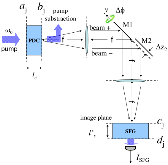
iii) A simplified scheme is illustrated in Fig.1. A first nonlinear crystal, pumped by a broad coherent pump beam, generates PDC radiation. After eliminating the pump beam, the exit face of the PDC crystal is imaged onto the entrance face of a second nonlinear crystal, where the inverse SFG process takes place. This is described in Fig.1 by a 4-f lens imaging system: in a real implementation, however, dispersive optical elements should be avoided as much as possible, since dispersion would drastically deteriorate the phase-sensitive correlation. The use of parabolic mirrors in place of lenses is a valid alternative, as we recently demonstrated in jedr2011 ; jedr2012 .
iv) In order to have an efficient up-conversion process, the SFG and PDC crystals must be of the same material and cut for the same phase-matching conditions, while their lengths can differ.
v) We focus on type I PDC, and in the following we shall always refer to the case of BBO (Beta-Barium-Borate) crystal pumped at 527nm in a e-oo phase-matching configuration. The PDC field is then described by a single field operator (ordinarily polarized), while the pump field is extraordinarily polarized.
vi) In order to explore the full spatio-temporal structure of PDC entanglement, a key requirement is the ability to impose independently a temporal delay and a transverse spatial displacement between the two twin components of PDC radiation. The twin components of the signal beams can be manipulated separately in the 2f plane of the imaging device (the far-field plane with respect to both the PDC crystal exit face and the SFG crystal entrance face): the reason is that for a broad pump beam twin photons are always emitted with opposite transverse wave-vectors and , so that when a photon is found in the upper half of the 2-f plane, its twin will always be in the lower half plane. We shall denote by beam + and beam -, respectively, the upper and lower portions of the 2f plane, which correspond to the two portions of the PDC radiation having positive and negative components of the transverse wave vector along the -axis in Fig.1.
vii) Since the PDC correlation is strongly localized both in space and time (in the micrometer and femtosecond range respectively gatti2009 ; caspani2010 ; brambilla2010 ), the temporal and spatial relative displacements of the twin beams must be scanned with micrometric precision. This can be realized by means of the two plane mirrors M1 and M2 placed in the 2-f plane of the telescopic system. As it will be described in detail in the following , a rotation of mirror M1 by an angle generates at the SFG crystal input face a transverse displacement of beam + of an amount , while a translation of mirror M2 by a distance generates a temporal delay .
The intensity of the up-converted field generated by the SFG process in the second crystal is then monitored as a function of the relative temporal delay and spatial shift of the twin beams. The main idea that we will demonstrate is that this quantity is able to give a precise information about the structure of the correlation of twin beams generated in the first crystal and can be used in order to reconstruct the shape of this correlation in space and in time.
In the treatment that follows we develop a model that takes fully into account the propagation effects and the phase-matching mechanism that selects the spatio-temporal frequencies in both crystals.
II Modeling the optical system
In order to describe the scheme of Fig.1, we consider
separately the propagation in the PDC crystal (Step I), the linear propagation between the two crystals (Step II) and the up-conversion process in the second crystal (Step III).
As indicated in Fig.1, the field operators in the different planes of interest will be labeled with
- at the input plane of the PDC crystal;
- at the output plane of the PDC crystal;
- at the input plane of the SFG crystal;
- at the output plane of the SFG crystal.
The index refers to beams with central frequency (either the pump field in the first crystal or the up-converted field in the second crystal), the index to the beams of central frequency (either the down-converted field in the first crystal or the fundamental field in the SFG crystal).
The description of field evolution along , the mean propagation axis of the system, will be performed either in the direct spatio temporal space , where is the 2D transverse coordinate and is time, or in the Fourier spatio-temporal domain where is the transverse component of the wave-vector and denotes the frequency offset from the central frequency.
For convenience, we shall use a compact notation for these space-time coordinates
by making the substitutions
| (1a) | |||
| (1b) | |||
| (1c) | |||
Our analysis will be carried out at two levels
1) In the limit where the pump beam driving the PDC process is broad and long enough, we shall adopt the plane-wave pump approximation (PWPA), which allows us to derive analytical or semi-analytical results. This model will be presented in the next sections II-VI .
2)In order to obtain results for a finite pump, we also developed a full 3D+1 numerical model, based on stochastic simulation of field evolutions. This model will be introduced in Sec. VI
Step I: propagation in the PDC crystal
In this section we describe the model we use to describe PDC (also derived in gatti2003 ; gatti2009 ; caspani2010 ), and we recall the main features of the space-time correlation of PDC light that we called X-entanglement gatti2009 ; caspani2010 ; brambilla2010 .
The pump and down-converted fields are described by two field operators and , centered around the frequencies and , respectively. Normalization is such that gives the photon number per unit area and unit time. The generation of the PDC field along the nonlinear crystal takes its simplest form in the Fourier domain
| (2) |
where we recall that is the set of 3D Fourier coordinates, , while is the longitudinal coordinate along the mean propagation direction in the crystal. Next, we introduce the slowly varying amplitudes
| (3a) | |||||
| (3b) | |||||
where is the z-component of the wave-vector for the -field. These amplitudes vary slowly along the -coordinate, because their evolution is only due to the nonlinear interaction, since we have subtracted the effect of the fast linear propagation contained in the phase factor . We can assume the pump beam is undepleted by the PDC, so that its evolution is only linear . In the same approximation, the pump operator can be substituted by its c-number amplitude . The propagation equation for the signal field contains only first-order z-derivatives and takes the form gatti2003 ; gatti2009
| (4) | |||||
Here the phase matching function
| (5) |
describes the phase-mismatch between the two generated signal modes , and the pump mode . Efficient down-conversion takes place only in those modes for which the phase-mismatch is small. The coupling constant is defined by
| (6) |
where is the effective second order susceptibility of the nonlinear crystal, and are the refraction indexes at the central frequencies and .
Eq.(4) can be analytically solved in the plane-wave pump approximation, , where denotes the pump field peak value in direct space. As analyzed in detail in caspani2010 , such an approximation holds as long as the pump beam waist and duration are larger than the spatial transverse displacement and temporal delay experienced by the pump and signal beams along the crystal because of walk-off and group velocity dispersion (in the example of a 4mm long BBO, a pump pulse with a waist larger than m and a duration above fs satisfies this condition). The solution is expressed by a unitary transformation linking the field operators at the output face of the crystal, , to those at at the input face, :
| (7) |
The explicit expression of the functions and can be found e.g. in caspani2010 . Here we notice that they depend on only through the plane-wave phase mismatch
| (8) |
where is the wave number of the pump. All the properties of the PDC light are described by the following second-order field correlation functions
| (9a) | |||
| (9b) | |||
In particular, from Eq. (9b), we see that the function
| (10) |
represents the probability amplitude that a pump photon at is down-converted into a pair of phase-conjugated photons and . Its explicit expression is
| (11a) | |||||
| (11b) | |||||
where is the dimensionless gain parameter proportional to the pump peak amplitude
| (12) |
The other relevant function is the PDC spatio-temporal spectrum
| (13) |
which gives the photon number distribution in the spatio-temporal Fourier domain.
We remark that equations (4)-(13) are valid in any gain regime of PDC. In the low gain regime they describe the down-conversion of pump photons into pairs of signal-idler photons that can be resolved individually. In the high gain regime stimulated down-conversion becomes important, and these equations describe the generation of macroscopic twin beams of light made of ”bunched” pairs of twin photons.
In particular, in the low-gain regime Eq. (11) takes the well known Sinc dependence on the phase mismatch:
| (14) |
In Ref. gatti2009 the name X-entanglement was used to describe the shape of the spatio-temporal correlation of the biphoton amplitude at the crystal output face. The quantity of interest is therefore:
| (15) |
which in the stationary plane-wave pump regime depends only on the relative spatial and temporal coordinates . It can be expressed caspani2010 as the Fourier transform of the spectral probability amplitude of generating photons in phase conjugate modes and , that is
| (16) |
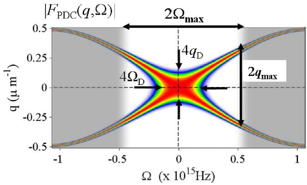
Fig. 2 shows the behaviour of for collinear phase matching, calculated by using the Sellmaier relations for the refractive indexes boeuf2000 . As can be inferred from Eqs. (11) and (14), in any gain regime is strongly peaked around the phase matching curves defined by . The hyperbolic geometry displayed in the neighborhood of degeneracy can be understood
by making a quadratic expansion of around
| (17) |
where , and . 111A detailed discussion on the range of validity of the approximations (17) can be found in brambilla2010 in the context of type II phase-matching. The phase-matching function (8) takes then the quadratic form
| (18) |
where is the collinear phase-mismatch parameter, and
| (19) |
and determine the characteristic scale of variations of along the -axis, at fixed , and along the -axis at fixed , respectively. They scale with the inverse square root of the crystal length and are generally much smaller than the range of frequencies of the whole PDC emission spectrum (the latter can in principle extend up to the pump optical frequency). When tuning the crystal for collinear phase matching, i.e for , phase-matching occurs along the lines . Under this condition, we notice that the first zeros of the function (see Eq.(11b)) along the and axis, evaluated using approximation (18)
| (20) |
provide good estimates of the widths of along those axis, which takes into account the gain broadening effect in the spectral domain. For the example shown in Fig.2, with , we have , , as indicated by the arrows.
The hyperbolic geometry of phase matching in the spectral domain turns into a characteristic X-shaped geometry for the spatio-temporal biphoton correlation (16). Figure 3a shows the profile of as a function of the relative spatial and temporal coordinates. (only one transverse dimension is shown).
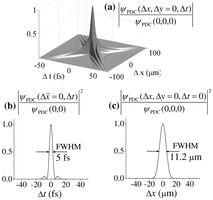
The tails of the structure are oriented along the lines , a feature expressing a linear relation between the temporal delay and the spatial transverse separation acquired by the twin photons when arriving at the crystal output face gatti2009 ; caspani2010 , i.e. making use of the equations (19)
| (21) |
As described in detail in caspani2010 , when tilting the crystal away from collinear phase matching, this linear relation becomes less and less stringent: as a consequence the tails of the structure become progressively less visible. The phase-matching condition represents therefore the optimal configuration to observe the X-entanglement.
A relevant feature of the X-entanglement is the strong localization of the central peak of the correlation function, whose cross-sections along the temporal and the spatial axes are shown in the lower part of Fig.3 . The width of the peak is in principle determined by the inverse of the full PDC emission bandwidth, or in practice by the bandwidth intercepted in the measurement. In the example of the figure, we simulated the presence of a filter in the temporal frequency of width Hz (indicated by the unshaded region in Fig.2), which corresponds to a wavelength interval ranging from nm up to the conjugate wavelength nm. The temporal profile of the correlation in Fig.3 has a full width half-maximum fs, close to that of the Fourier transform of a box function of width . The spatial width of the correlation peak, in turn, is determined by the range of spatial frequencies involved in the PDC emission, and typically is on the order of a few microns.
Step II: propagation between the two crystals
We assume ideally that the optical setup illustrated in Fig.1 behaves as a perfect imaging system, free from dispersion and losses. In the absence of any temporal delay and spatial shift (), the PDC field at the PDC crystal exit face is then mapped into the SFG crystal entrance face 222For simplicity we neglect here and in the following the spatial reflection with respect to the -axis , as well as constant phase factors . In order to model the effect of a small rotation of mirror and a small translation of mirror M2 we assume that the propagation angles in play are such that the paraxial approximation holds.
Let us first consider the temporal delay applied to the Fourier modes of the PDC light (beam -). By translating the mirror M2 by the separation between the two lenses in Fig. 1 becomes . The fields at frequency at the left and right focal planes of the imaging device are related through the algebraic transformation (the reflection is omitted)
| (22) |
The effect of diffraction due to the additional propagation is described, within the paraxial approximation, by the quadratic phase factor proportional to . Its effect can be neglected as long as
| (23) |
Referring to the conditions of the experiment jedr2011 ; jedr2012 , for cm, m and mm the condition reads cm. In order to explore the X-shaped PDC correlation, delays of a few hundreds femtoseconds at most are sufficient (see e.g. the plot in Fig. 3a), so that in practice condition (23) is always fulfilled. Each Fourier mode of beam - undergoes therefore, within a very good approximation, the following diffractionless transformation
| (24) |
where an inessential constant phase factor has been omitted.
We now consider the manipulation of beam + through the rotating mirror M1. As shown in App.A, a rotation of M1 by a small angle around a given axis generates a transverse shift of the beam at the entrance face of the SFG crystal (the imaging plane), in the direction orthogonal to the rotation axis. According to Eq. (6), the complete transformation undergone by beam + between the input and output planes of the 4- telescopic system can be written in the Fourier domain in the form (the reflection and the minus sign are here omitted for simplicity)
| (25) |
where denotes the transverse shift generated by a rotation of mirror M1 around a generic axis. Putting together relation (24) and (25), the overall transformation describing propagation from the PDC crystal output face to the SFG crystal input face can therefore be synthesized into the following unitary input-output relation
| (26) |
where denotes the step function, equal to 1 for , to zero for , and
| (27) |
are the transfer functions associated to beam and beam , respectively. The identity guarantees that the commutation rules are preserved by the transformation.
It is important to notice that the correlation measurement depends on the particular choice of the rotation axis of M1, as it will be shown in Sec.IV. We shall consider explicitly the two configurations illustrated in Fig.4: in case a) M1 is rotated around the -axis orthogonal to the gap between the two mirrors, while in case b) the rotation axis of M1 is coincident with the -axis (orthogonal to the figure plane). We have thus
| (28a) | |||
| (28b) | |||
where and denote a small rotation angle applied to the mirror around the -axis in configuration (a), around -axis in configuration (b).
Step III: propagation in the SFG crystal
We now model the generation of the up-converted field inside the SFG crystal. This process is just the reverse of the down-conversion described in Sec. II. Following the same procedure outlined there, we work in the Fourier domain and we introduce the slowly varying amplitudes of the fundamental (carrier frequency ), and second harmonic (carrier frequency ) fields along the SFG crystal
| (29a) | |||||
| (29b) | |||||
which vary along only because of the nonlinear interaction, since we have subtracted the effect of linear propagation. Their evolution is described by the following pair of coupled equations:
| (30a) | |||||
| (30b) | |||||
Equation (30a) describes all the up-conversion processes where a pair of fundamental photons in modes , are up-converted into a SFG photon in mode . Accordingly, in this equation represents the phase mismatch of such a process in the second SFG crystal. Equation(30b) is obviously just the same as Eq. (4) describing the down-conversion process.
Equations (30) need to be considered together with the initial conditions at the crystal input face. For the fundamental field we have
| (31) |
where is the field down-converted in the first PDC crystal, after Step I and II. For the second harmonic field, we assume that the pump field is completely eliminated after the PDC crystal, so that it is in the vacuum state at the SFG crystal input.
We now assume that the SFG crystal is short enough so that only a small fraction of the PDC light is up-converted. In these conditions, the fundamental field remains basically unchanged during propagation, and Eq.(30) can be solved with a perturbative approach similar to that used in the low gain regime of PDC in Ref.caspani2010 (see App.A therein). In this way, we obtain an explicit expression that links the operators at the SFG crystal output plane to those at the SFG input plane:
| (32a) | |||||
| (32b) | |||||
where
| (33) |
The function can be interpreted as the probability amplitude density 333Its square modulus gives the probability per unit of spectral bandwidth. that a pair of photons in the fundamental modes and are up-converted into the second-harmonic mode : this up-conversion probability is non negligible only for those pair of modes for which the phase-mismatch . As it can be expected, the probability amplitude for such a process is formally identical to that of the reverse process of down-conversion. Eq.(33) has indeed the same form as Eq. (14), the main difference being that Eq. (14) describes PDC only in the plane wave pump limit, where the only allowed down-conversion processes are those leading to twin photons in modes and .
III General solution: the SFG coherence function
We now put together the chain of field transformations presented in the previous section. Our main goal will be to evaluate the intensity of the SFG field, but we start from a more general result, i.e. the coherence function of the SFG field in the spectral domain, evaluated at the output face of the SFG crystal
| (34) |
Inserting the input output relation (32b) for the SFG crystal inside this expression, we obtain an equation that links the SFG coherence function to the correlation functions of the fundamental field at crystal input face. These correlations can be calculated by using relations (9) together with the identities and . We obtain the following expression
| (35a) | |||||
| (35b) | |||||
Using these relations we obtain after some manipulations the following result
| (36) |
with
| (37a) | |||
| (37b) | |||
where and are the spectral probability amplitude defined in Eqs.(11) and (33).
The incoherent term (37a) originates from the up-conversion of PDC photons which do not belong to phase-conjugated mode pairs. By contrast, the coherent term (37b) originates from the up-conversion of photon pairs coming from phase-conjugate PDC modes, this latter process leading to the partial reconstruction of the original coherent pump beam as described in the experiment in Ref.jedr2011 . In this regard, it is convenient to introduce a special symbol for the up-conversion probability amplitude appearing in Eq.(37b), namely
| (38a) | |||||
| (38b) | |||||
where
| (39) |
is the phase mismatch function for these coherent up-conversion processes. The function plays a fundamental role in determining the properties of the coherent component of the SFG field. It describes the efficiency with which photons belonging to a particular pair of phase-conjugated modes and undergoes the inverse process of the original PDC event, i.e. the back-conversion into the monochromatic plane-wave mode corresponding to the original pump driving the PDC. The corresponding phase-mismatch is identical to the PDC phase-matching function (8) except for the presence of the wavenumber , which differs from the pump wave number only in the case when the two crystals are not perfectly aligned (for the type I e-oo phase-matching we are considering only the pump beam -vector depends on direction). When the two crystals are aligned, coincides with the probability amplitude for the reverse PDC process in the low-gain regime, as given by Eq.(14) (apart from a constant factor).
As can be inferred by comparing Eq.(37b) and Eq.(16), only the coherent contribution contains the information about the biphoton correlation we are looking for. The incoherent contribution rather acts as a background which tends to deteriorates the visibility of the correlation measurement dayan2007 .
Notice also that the coherent component (37b) factorizes into the product of the SFG field mean values:
| (40) |
with
From Eqs.(36)-(37) we can evaluate the SFG intensity (number of photons per unit area and unit time) at the exit face of the 2nd crystal, obtaining
| (42) |
with
| (43a) | |||
| (43b) | |||
The intensity distribution of the SFG light in the near-field is uniform in space and time, an artifact due the spatio-temporal invariance of our model deriving from the monochromatic and plane-wave pump approximation. By comparing Eq.(37b) and Eq.(43b), we obtain the following relevant identity
| (44) |
which shows that the coherent component of the SFG field contains the same kind of information on the biphoton amplitude both in the space-time domain and in the spectral domain. The most important difference lies in that the coherent intensity in the spectral domain is concentrated in a single peak at the origin , i.e. in the mode corresponding to the original pump field. On the other hand, the spectrum of the incoherent background is delta-correlated in space and time, and spreads over a very broad range of spatial and temporal frequencies, its particular shape being related to the phase-matching conditions inside the SFG crystal as it will be elucidated in brambilla2012 . This circumstance suggests that either far-field or spectral measurement may be conveniently used to enhance the visibility of the coherent contribution with respect to the incoherent background.
IV Retrieving the PDC correlation
Let us now investigate how the information on the correlation of twin beams/ twin photons can be effectively extracted from the coherent component of the SFG light, given by Eq.(43b). Making explicit the dependence on the temporal delay and spatial shift applied to beam + and beam - contained in the transfer functions (27), it can be written in the form
| (45) |
where
| (46) |
and .
In this section we consider the configuration shown in Fig.4a, where mirror M1 is rotated orthogonally to the gap between the two movable mirrors so that . In this case, the r.h.s. of Eq.(45) coincides with the square modulus of the following quantity
| (47) | |||
The step function could be eliminated from Eq.(46) by
exploiting the parity of integrand with respect to , the latter being a consequence of
the radial symmetry of and in the -plane.
The function , like , is therefore an even function of both the spatial and the temporal coordinates,
a feature not holding for the alternative configuration with mirror M1 rotating around the -axis (see Fig.4b)
which will be discussed in the next section.
Figure 5 plots the coherent contribution of the SFG intensity as a function of the applied spatial and
the temporal shifts. In this example,
the two crystals have the same lengths mm and the PDC gain is .
The structure preserves the nonfactorable X-shaped geometry of the original PDC correlation function shown in Fig.3,
with symmetric tails developing along the bisector lines (corresponding to the diagonals of the plot frame).
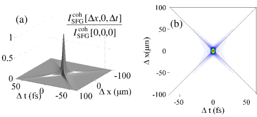
The SFG coherent component (47) differs from the PDC biphoton correlation defined in Eq.(16) only for the presence of the SFG spectral amplitude . The latter describes how the phase matching mechanism selects the spatio-temporal modes in the coherent up-conversion process. We shall analyse in detail how it affects the PDC correlation measurement in the next subsection. In this regard, it is useful to recast Eq.(46) in the form of a convolution of the PDC biphoton amplitude - the quantity under investigation - with the Fourier transform of , i.e.
| (48) |
where
| (49) |
This identity has been written taking into account that , so that the step function could be eliminated as for Eq.(47). Noticing that Eqs.(49)-(38) are formally identical to Eqs.(16)-(14), we see that is proportional to the low gain biphoton amplitude in the space-time domain for the second SFG crystals. It represents the probability amplitude that a pair of photons delayed by a time and displaced by are coherently back-converted into the plane-wave pump mode . This function can be also interpreted as the optical response function of the SFG crystal in the measurement of via SFG.
IV.1 Thin SFG crystal limit
Let us assume that the two crystals are tuned for the same phase matching conditions, so that ,
but the SFG crystal is much shorter than the PDC crystal . In this limit, the PDC biphoton amplitude can be exactly reconstructed by monitoring the SFG coherent component.
This can be shown by inspection of Eq. (46). When the same phase matching conditions hold in the two crystals, the spectral probability amplitudes and are peaked around the same geometrical curve . However, for the spectral bandwidths in the SFG crystal are much wider than in the PDC crystal (the bandwidths of exceeds those of by a factor , according to Eq.(19). As a result,
is almost constant in the region where is not negligible, close to its maximum value .
Under these conditions, the filtering effect due to phase-matching in the SFG crystal becomes ineffective and we have
| (50) |
Thus the coherent component of the SFG output reproduces the biphoton correlation as anticipated.
The same conclusion can be derived also looking at Eq. (48): in the limit , the biphoton amplitude , defined by Eq. (49), has scales of variation in space and time much shorter than , because it is the Fourier transform of a much wider spectral amplitude. It behaves therefore as a -function inside the convolution integral (48), so that the PDC biphoton amplitude
is recovered.
For completeness, we mention that in the limit the incoherent contribution (43a) takes the form
| (51) |
where
| (52) |
is the PDC photon flux evaluated at the output face of the first crystal [as can be easily inferred from relation (9a)]. However, we shall see in Sec.VI that the temporal walk-off between the PDC field and the generated incoherent SFG field plays a fundamental role in the formation of the incoherent component even when considering short propagation distances. In practice, the validity of expressions (51) fails as soon as the finite length of the SFG crystal is taken into account.
IV.2 Long SFG crystal
We now investigate how propagation in the SFG crystal affects the retrieval of the PDC correlation via the measurement of , showing that both the X-shaped geometry and the strong localization of the biphoton correlation are preserved, at least when the two crystals are equally tuned.
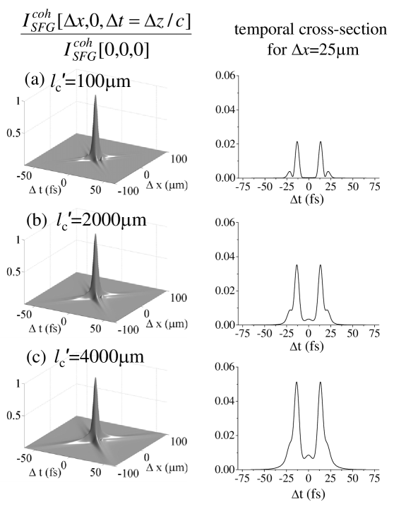
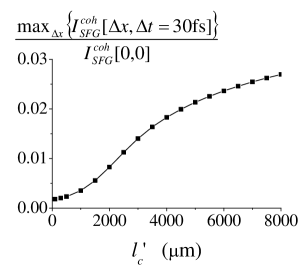
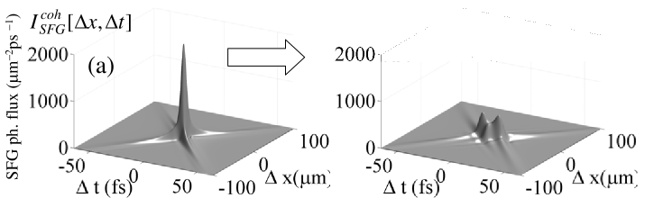
The left panels of Fig.6 plot the retrieved quantity for increasing values of the SFG crystal length . The most evident effect is that the tails of the correlation becomes progressively more visible with respect to the central peak, as the propagation distance inside the SFG crystal increases. This is clearly shown by the temporal cross-sections at m of the same quantity (right panels of Fig.6). Figure 7 shows that the height of the tails, at a fixed time delay fs, increases almost linearly with up to the value of the PDC crystal length mm. We expect therefore that the choice of a few millimeter long SFG crystal, with respect to that of a very short crystal, presents a twofold advantage: i) the total number of up-converted photons is obviously larger and ii) the visibility of the tails, although small with respect to that of the central peak, will be enhanced, a feature which should facilitate the experimental observation of the X-shaped structure through the scanning of and . A further advantage lies in that the overall visibility of the coherent component with respect to the incoherent background improves substantially as the SFG crystal length is raised above a few hundred of microns, as it will be shown in Sec.VI.
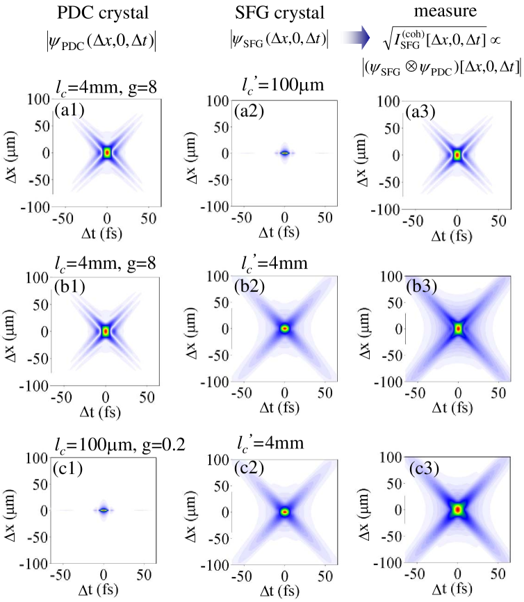
An explanation of the behaviour depicted in Fig.6 can be obtained considering the convolution integral in Eq.(48) and referring to the density plots of Fig. 8, which illustrate the effect of the convolution (48) under three different
conditions:
(a) : the SFG crystal response function behaves as a Dirac -function both in the spatial and temporal
domain (see plot a2), so that the 2nd crystal works as an ultrafast correlator with instantaneous and localized response.
The coherent component of the SFG intensity (plot a3) provides therefore the PDC biphoton amplitude
square modulus , in agreement with the short crystal limit result (50).
(b) : if the SFG crystal has a length comparable to that of the PDC
crystal, it displays a nonlocal spatio-temporal response. However, provided the two crystals are tuned for the same phase matching conditions, the response of the SFG crystal has the same geometrical X-shape as the original biphoton correlation [see plots (b1) and (b2)].
This does not come unexpected: as a matter of fact, the function is identical to in the low PDC gain limit (apart from a constant factor). In the high gain regime of PDC considered in this example, the PDC biphoton amplitude displays a faster decay of the tails than its low gain counterpart,444The faster decay of the PDC correlation along its tails for high gain is due to the broadening of the spectral amplitude with described by Eq.(20).
but nevertheless keeps the same geometrical shape. Therefore is
the convolution of two functions which have almost the same X-shaped structure in the space-time domain, and the
main effect of this convolution is to enhance the weight of the tails with respect to the central peak,
as can be seen from plot (b3).
Most-importantly from our point of view, the non-factorable X-shaped geometry of the PDC biphoton amplitude is preserved, as well as its strong localization in time (or in space) when particular temporal (or spatial) cross-sections are considered.
(c) .
Because of the symmetrical role played by and in Eq.(48),
a configuration with would provide a direct measure of , which is proportional to the
PWP biphoton amplitude in the SFG crystal at low parametric gains (accordingly, the density plots (c2) and (c3) are nearly identical,
as for the plots (a1) and (a3) in case a).
However, in this case the SFG photon flux would be strongly reduced because of the lower gain of the PDC field associated with short crystals.
V Alternative detection scheme
We now focus on the alternative configuration (b) for mirror M1 shown in Fig.4b, considering rotations performed around the -axis. In contrast to configuration (a) treated in the previous section, the step function cannot be eliminated from Eq.(46) and the SFG coherent component is now given by the square modulus of
| (53) |
with .
Because of the presence of the step function, the even symmetry with respect to the spatial coordinate is lost. As shown in Fig.9, the retrieved correlation function in the -plane display a V-shaped geometry: the tails extends along the lines in the half-plane, while they disappears for . Moreover, compared to the result obtained in configuration (a) shown in Fig.5, the tails are strongly enhanced with respect to the central peak. From simple geometrical optics considerations, it can be shown that negative values of the rotation angle of mirror M1 around the -axis prevents the overlap of beam + and beam - inside the SFG crystal, so that the up-conversion efficiency becomes much lower under this condition (i.e for ). On the contrary, a negative rotation increases the overlap of beam + and beam -, enhancing thereby the up-conversion efficiency compared to configuration (a) in the region.

Noticing that the complex amplitude and given by Eq.(47) and Eq.(53) are linked through the relation
| (54) |
from which it can be inferred that the temporal profile across the central peak [obtained by setting in case (a), in case (b)] is identical in the two configurations (see Fig.10a). On the other hand, being in the region not too close to the central peak, relation (V) implies that for and for . The tails of the coherent SFG component, extending only in the region in configuration (b), are thus about four times more intense than in configuration (a). This behaviour is shown in Fig.10b,c, which compares the temporal profile in the two configurations for the spatial shifts m and m respectively.
We notice that configuration (b) offers the relevant benefit that the tails are more visible and can be therefore detected more easily than in configuration (a). Although in principle configuration (b) does not allow the reconstruction of the symmetric X-shaped correlation as configuration (a), we found the following approximate empirical relation that links the results in the two configurations:
this approximation holding as long as is sufficiently large, i.e. far from the central peak. This relation should allow to infer from experimental data collected in configuration (b) the data that would be collected in configuration (a) , thus allowing the reconstruction of the X-shaped PDC correlation in configuration (b) .
VI Visibility of the information
The issue of the visibility of the information contained in the coherent SFG contribution, against the incoherent background, is a crucial one, especially for the observation of the tails of the PDC X-shaped correlation.
As already remarked, the expression (37) of the spectral coherence function of the SFG light, suggests that the visibility should be greatly enhanced by measuring the SFG light in the far-field of the second crystal, where the coherent contribution propagating in the forward direction is separated from the incoherent background propagating over a broad angle. This issue will be discussed in Sec.VI.2. We start here by considering the visibility of a measurement of the total number of SFG photons, which provides a useful estimation of the overall weight of the coherent component with respect to the incoherent one.
VI.1 Bucket detection of the SFG photons
The photon fluxes and given in Sec.III, Eqs.(43), have been evaluated at the SFG crystal output face and are are uniform in the transverse plane because of the artifact of the plane-wave pump approximation. Within this limit, the ratio
| (56) |
defines therefore the visibility of the correlation peak at against the incoherent background either in the case of a near-field detection of the SFG intensity or assuming all the SFG photons are collected without discrimination (e.g. by using a bucket detector).
Figure 11 plots the visibility as a function of the length of the SFG crystal for increasing PDC parametric gain, starting from values of below unity (Fig.11a) up to very high values (Fig.11b), the latter corresponding to the regime of the experiment reported in jedr2011 . The contributions of both the coherent and the incoherent components (43b) and (43a) have been estimated numerically with a Monte Carlo integration, assuming a 550 nm FWHM temporal bandwidth is selected with a super-Gaussian frequency filter from 850 nm up to 1400 nm.
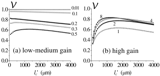
In a regime of low parametric gain, i.e. for , the PDC spectral probability amplitude
scales as [see Equation (14)], while the spectrum given by Eq.(13) scales as .
For this reason and scale as and ,respectively,
and the visibility (56) is close to . This behaviour can be physically understood by noticing
that the probability of finding pair of photons that are not twins becomes exceedingly low in this regime.
As the PDC parametric gain increases, the incoherent component rapidly increases and becomes comparable to the coherent one.
As a consequence, decreases to lower values, the degradation being particularly relevant in
the limit. For longer propagation distances in the SFG crystal, the generation of incoherent SFG photons
becomes less efficient because of spatial walk-off and GVM, while the coherent component is not affected by those phenomena,
as it will be further discussed in brambilla2012 .
The visibility remains therefore above even for high PDC gains,
as long as the propagation distance inside the SFG crystal exceeds a few hundred micrometers. However, we notice that such
visibility, although not negligible, would make the detection of the full X-correlation very challenging in a practical implementation, because the tails would be hidden by the incoherent background.
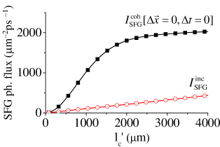
Fig.12 displays separately and as a function of , evaluated in the high-gain case () from Eq.(43). It shows that the coherent component increases almost quadratically up to mm, while for larger propagation distance in the SFG crystal the coherent up-conversion becomes less efficient. The initial quadratic behaviour reflects the result of Eq. (50) derived in the ”thin SFG crystal” limit, where the filtering effect due to the SFG spectral probability amplitude in Eq.(43b) is almost ineffective.
By inspecting the expression of the typical bandwidths of and [only the latter depends on the parametric gain according to Eq.(20)], we find that they become comparable for mm for , mm. For above this characteristic length the SFG spectral probability amplitude becomes narrower than , and the integral (43b) spans a volume in the Fourier space , so that does not scale any more as .
On the other side, the SFG incoherent component increases only linearly with , except for very short propagation distances for which approximation (51) holds. This is due to the fact that the up-conversion probability appearing inside the integral at r.h.s. of (43a) decays rapidly when , because of the effect of the spatial walk-off and the temporal group velocity mismatch arising between the ordinary fundamental beam and the extraordinary up-converted beam. This issues will be further elucidated in a forthcoming related publication brambilla2012 .
VI.2 Far-field detection of the SFG light
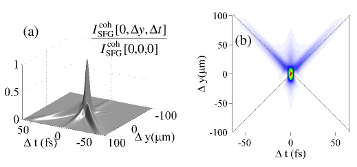
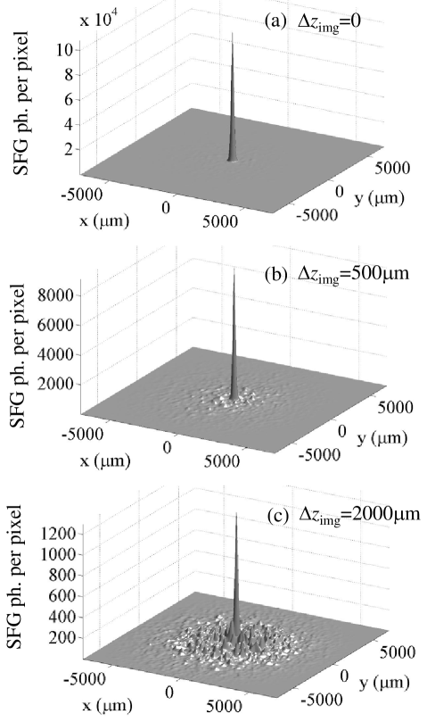
According to the plane-wave pump result of (37), the spectral distribution of the PDC light consists of a coherent contribution, concentrated in the original plane-wave pump mode at and , superimposed to an incoherent background that spreads over a large bandwidth of spatio-temporal modes. The PWP approximations leads to artificial divergences (the -functions factors) that do not allow a direct evaluation of the visibility of the coherent component against the incoherent background in the Fourier domain. For this reason, we implemented a full 3D+1 numerical simulation of our proposed setup (see Fig.3), and modeled the result of the detection of the SFG intensity distribution in the far field of the SFG crystal, as shown in fig.13a. The generation of the broadband PDC field is simulated in the framework of the Wigner representation as described in brambilla2004 , taking into account both the finite cross section and duration of the pump pulse, and the phase-matching conditions inside the two crystals (the full BBO Sellmeier dispersion relation boeuf2000 are used in the simulation). The propagation in the two crystals, described by Eqs.(4) and (30), is simulated through a pseudo-spectral (split-step) method using a numerical grid in the and the spaces. The parameters of the numerical simulations are chosen to reproduce the conditions of the experiment being developed in Como jedr2011 , which operates in a pulsed regime of high parametric gain . The broadband PDC field injected into the SFG crystal after the extraction of the pump beam undergoes the three-wave mixing process described by Eqs.(30) and the up-converted SFG field is mapped into the far-field with an f-f lens system, as shown schematically in Fig.13a. We expect that a single stochastic realization of our simulations roughly reproduces the field distribution obtained from a single pump shot.
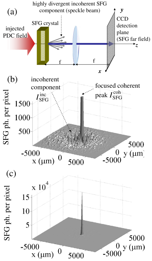
The typical far-field intensity distribution of the up-converted SFG field obtained in the detection plane from a Gaussian pump pulse of waist
m and duration ps is shown in Fig.13b,c.
We verified that for the chosen PDC gain g=8
the injected PDC field (not shown in the figure) is only slightly depleted during propagation in the second crystal (),
a feature which confirms the validity of the perturbative approximation (32b) for the SFG field used in the PWPA model.
The narrow central peak results from coherent processes in which pairs of phase conjugate photons back-convert to a coherent field component reproducing partially the far-field distribution of the original pump beam. This peak is fixed, in the sense that it is reproduced identically in each stochastic simulation. The broad speckled background instead is noisy and changes in each realization, giving rise on average to a broad distribution. It originates from the incoherent processes where not phase-conjugated photon pairs are up-converted.
These kind of simulations reproduce very closely the results on the far-field detection of SFG reported in jedr2011 (see in particular Fig.4 therein).
The full scale plot in Fig.13 c shows that in such ideal conditions (perfect imaging, no dispersive optical elements, no misalignments between the two crystals) the visibility of the coherent vs incoherent component for is very high, close to .
We can therefore expect that this far field detection scheme is well suited for performing the measurement of the full X correlation.
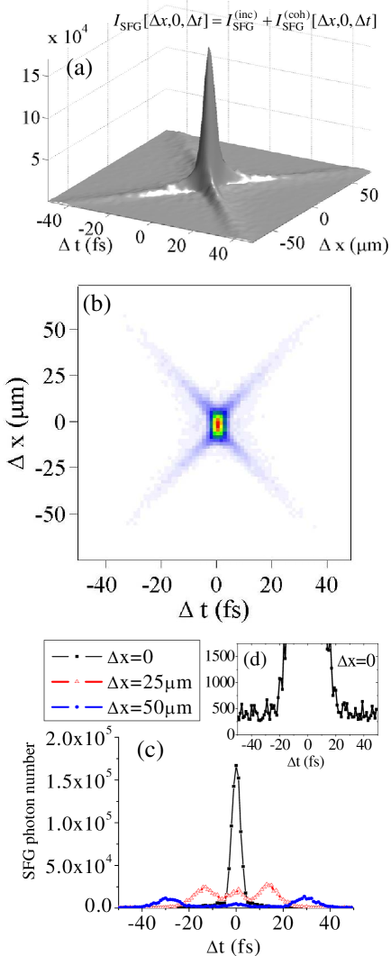
Figure 14 simulates the reconstruction of the X-shaped correlation obtained by monitoring the number of photons in the central peak of the SFG far-field as a function of the temporal delay and the spatial shift imposed on the two twin PDC components (more precisely, it reports the number of SFG photons over a pixel 56 x 56 wide, in the focal plane of a lens with f=20 cm, placed at a focal distance from the SFG crystal). We verified that for the chosen pump pulse parameters, the retrieved structure in the -plane is very close to that obtained by evaluating the coherent component (47) within the PWPA (see e.g. Fig.9a). Notice that despite the fact that both the coherent and the incoherent components are displayed in Fig.14, the visibility of the tails of the correlation with respect to the speckled background is very high. The relative weight of the incoherent background, about 0.2% of the coherent peak value, can be inferred from the height of the baseline of the temporal profile plotted in inset (d) for .
VII Fragility of the correlation measurement
The previous simulations that display nearly 100% visbility for the correlation measurement have been obtained assuming a perfect imaging of the PDC source into the SFG crystal input face. The coherent component is however strongly phase-sensitive and therefore extremely fragile against dispersion, imperfect imaging conditions, as well as small misalignments between the two crystals. For this reason, the slightest imperfection in the imaging device that maps the PDC output plane into the SFG input plane deteriorates the coherent component of the SFG field which contains the correlation information. On the other hand, the incoherent component (43a) remains unaffected because of its phase-insensitive nature, so that the overall visibility of is strongly sensitive to those imperfections. In the following we shall study the effects of the main sources of experimental imperfection.
VII.1 Temporal dispersion
It is well known dayan2005 ; peer2005b ; dayan2007 ; odonnel2009 that the scheme is very sensitive to the presence of any dispersive optical elements. As an example, Fig. 15 shows the effect of a half millimeter thick slab of BK7 glass inserted in the propagation path between the PDC and the SFG crystals.
It shows that not only the central correlation peak is broadened, but the X-shaped structure of correlation is strongly distorted. As a matter of fact, in order to compensate the detrimental effect of dispersion introduced by optical lenses, prisms have been used in the experimental works dayan2005 ; peer2005b ; odonnel2009 ; a valid alternative approach, which we implemented in jedr2011 ; jedr2012 is rather to replace dispersive lenses by achromatic parabolic mirrors.
VII.2 Imperfect imaging
Because of the smallness of the variation scale of the PDC X-correlation along the spatial dimension (m), we expect that the scheme shows very little tolerance with respect to errors in the positioning of the SFG crystal with respect to the image plane of the telescopic system illustrated in Fig.1. Under ideal imaging conditions, the spatial width of the correlation peak is indeed determined by the collected PDC bandwidth considered in the simulation, i.e. , which gives a spatial correlation profile of width m (see Fig.2a and Fig.3c).
Let us suppose for example that the second crystal entrance face is set at a distance from the second lens of the 4-f system. This error introduces an additional phase factor to the transfer function product that enters in Eq.(43b), which is now given by
| (57) |
The condition for neglecting the diffraction term reads
| (58) |
where is the maximal transverse wave-vector of the PDC emission in the collected bandwidth. For the temporal bandwidth Hz assumed in the simulations, we have a tolerance on on the order of hundred micrometers.
This is confirmed by our numerical modeling of the experiment. A first effect of an error in the imaging system is that the efficiency of the coherent up-conversion drops substantially with respect to the ideal configuration. Figure 16
shows the far-field distribution of the SFG light (as it would be detected in the scheme of Fig.13a), for increasing values of the error in the imaging plane . A displacement of is sufficient to decrease the back-conversion efficiency of the twin photons by a factor 12, and for mm the coherent peak becomes comparable in magnitude to the incoherent background (which is not sensitive to ).
Even more dramatical is the deterioration of the shape of the correlation function.
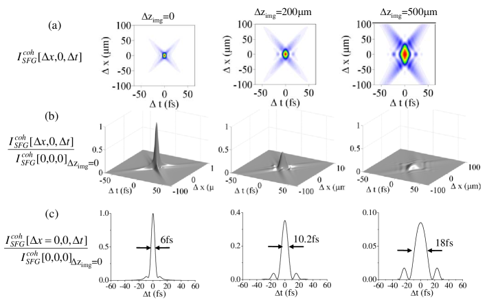
Figure 17 plots the spatio-temporal profile of the detected PDC correlation (row a and b) and of its temporal cross-section at (raw c) for increasing values of the error , evaluated from the PWPA result (43b).
The density plots in row a) shows that a large broadening occurs along the spatial direction. This is not unexpected: with to respect an error in the imaging plane, the reconstructed spatial correlation as a function of behaves as the spatial resolution of an ordinary optical image with respect to the depth of focus of the imaging system, i.e. it roughly broadens as
.
Less expected is perhaps the broadening of the correlation along the temporal direction, evidenced by raw c) in Fig.17. This temporal broadening is a clear consequence of the non-factorability of the twin-beam correlation in space and time. In turns, this is a consequence of the non-factorable character of phase matching: the phase matching condition [see Eq. (18)]
| (59) |
can indeed be read as a compensation of the temporal dispersion experienced by twin photons inside the PDC crystal due to diffraction.
Only if the entrance face of the second crystal is placed exactly in the image plane of the first crystal, this compensation occurs
and the biphoton correlation is a nearly transform limited coherent sum of the phase-matched spectral modes.
On the contrary, if the second crystal is misplaced with respect to the image plane, free propagation
deteriorates this exact compensation of dispersion and diffraction.
By making the simple assumption that only phase matched modes contribute to the coherent SFG
component (43b), we can make the substitution
in the propagation term at the r.h.s. of (57).
It transforms then into the dependent phase factor
which describes a quadratic dispersion-like chirp of the twin beams.
VII.3 Effect of misalignments of the two crystals
The coherent component of the SFG light is also strongly sensitive to misalignments of the SFG crystal with respect to the PDC crystal orientation. We investigated numerically the effect of a small tilt of the SFG crystal with respect to the PDC crystal orientation, the latter satisfying perfect phase-matching at degeneracy, i.e. . Figure 18 shows how the peak of the coherent contribution , i.e [see Eqs.(45)-(46)]:
| (60) |
rapidly goes to zero as the tilt angle exceeds a few tenths of degrees. As expected, takes its maximum value when the two crystals are perfectly aligned, as and , are peaked around the same phase-matching curves and their overlap integral is maximized.
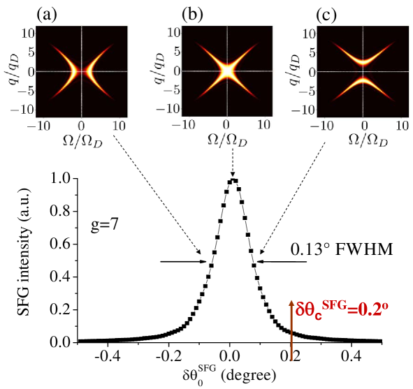
We can give a quantitative estimate of the angular tolerance in the alignment of the two crystals by considering explicitly the case when the second crystal is slightly tilted with respect to the first crystal, the latter being tuned for collinear phase matching. Denoting with the orientation angle of the PDC (SFG) crystals with the pump axis (i.e. the -axis), and assuming the tilt angle between the two crystals is small, the following approximate relation between the pump mode wavenumbers in the two crystals holds
| (61) |
where is the positive defined walk-off angle of the extraordinary wave at frequency . Since by assumption , according to Eq.(61) a negative tilt leads to a positive collinear phase-mismatch in the second crystal. At degeneracy the phase-matched spatial modes in the second crystal lye therefore on a circumference of radius
| (62) |
Close to degeneracy, the region of overlap of and can be expected to reduce drastically when coincides with the first node of the PDC probability amplitude along the spatial frequency axis, which is found to be well approximate by [see Eq.(20)]. Following this criterium, the overlap integral (60) will be reduced by a large amount when the tilt angle exceeds the critical value
| (63) |
Taking e.g. it gives us a tolerance in the alignment of the second BBO crystal with respect to the first. This value is in agreement with the numerical evaluation of as a function of shown in Fig.18.
VIII Conclusions
Our treatment shows that the SFG process represents a powerful tool for exploring the biphotonic correlation in the full spatio-temporal domain. Through a careful manipulation of both the spatial and the temporal degrees of freedom of the PDC field emitted by the first crystal, the proposed optical setup allows to retrieve the strongly localized X-shaped PDC correlation in the space time domain, predicted in gatti2009 ; caspani2010 ; brambilla2010 . The analytical result obtained within the PWPA shows that the coherent component of the up-converted SFG field contains the desired information on the PDC correlation function. In particular, this coherent component can be expressed in the form of a convolution between the PDC biphotonic function in direct space, the quantity under investigation, with the corresponding probability amplitude describing the up-conversion process in the SFG crystal, the convolution being evaluated at the applied temporal delay and spatial shift between two conjugate PDC components. It is shown that the measured quantity retains the main features of the biphotonic correlation, namely its nonfactorable X-shaped geometry and its strong localization in space and time. The latter, which can in principle reduce to a few pump optical cycles gatti2009 , is determined by the acceptance bandwidth of the up-conversion process. Finally, a fully 3D+1 numerical modeling of the optical setup that takes into account the pump pulse finite size has been implemented in order to provide a more realistic simulation of the experiment being implemented in Como. This allowed us to show that, even in the high gain regime of PDC, the visibility of the correlation measurement con be close to 100% when the up-converted light is collected in the far-field of the SFG crystal, and for evaluating the tolerance of the phase-sensitive correlation measurement against imperfection of the imaging system.
Acknowledgements.
We are grateful to Paolo di Trapani for precious suggestions and discussions. This work was realized in the framework of the Fet Open project of EC 221906 HIDEAS.Appendix A Derivation of Eqs.(26)-(27)
In this appendix we describe the effect of a rotating mirror set in the 2f-plane of a 4-f telescopic system. Let us consider a rotation by of the mirror across the -axis (orthogonal to the figure plane) with respect to its normal position set at with respect to the incident beam (dashed line in Fig.19). Because of reflection, the -vector of an incident mode with free space wavenumber and direction angle in the -plane is tilted by an additional angle with respect to the direction.

Accordingly, the -vector transverse and longitudinal component in the plane orthogonal to the rotation axis, and , transforms according to the orthogonal transformation
| (1a) | |||||
| (1b) | |||||
For small angles, i.e. for and , relations (1) reduces to
| (2) |
where all powers of and have been neglected except the linear terms. Under this approximation the relation between the reflected and the incident field, and , can be written as
| (3) |
The field Fourier transformation performed by the second lens of the system (see Fig.3) can be written as
| (4) | |||||
while that performed by the first lens can be written as
| (5) |
Combining Eqs.(3)-(5) together, we readily obtain the following transformation between the input and the output planes of the telescopic system
| (6) |
where denotes the transverse displacement of the field at the SFG crystal input plane produced by the mirror rotation. It is worth noticing that, under this approximation, the transverse shift is the same at all temporal frequencies.
References
- (1) A. Gatti, E. Brambilla, L. Caspani, O. Jedrkiewicz, and L. A. Lugiato, Phys.Rev. Lett. 102, 223601 (2009).
- (2) L. Caspani, E. Brambilla and A. Gatti, Phys. Rev. A 81, 033808 (2010).
- (3) E. Brambilla, L. Caspani, L.A. Lugiato and A. Gatti, Phys. Rev. A 82, 013835 (2010).
- (4) O. Jedrkiewicz, J.L. Blanchet, A. Gatti, E. Brambilla and P. Di Trapani, Opt. Expr., 19, 12903 (2011).
- (5) O. Jedrkiewicz, J.-L. Blanchet, E. Brambilla, O. Jedrkiewicz, L. A. Lugiato, and A. Gatti, submitted to Phys. Rev. Lett., preprint arXiv:1203.3661v1.
- (6) C.K. Hong, Z.Y. Ou, L. Mandel, Phys. Rev. Lett. 59, 2044 (1987)
- (7) Barak Dayan, Avi Peer, Asher A. Friesem, and Yaron Silberberg Phys. Rev. Lett. 94, 043602 (2005)
- (8) Avi Peer, Barak Dayan, Asher A. Friesem, and Yaron Silberberg Phys. Rev. Lett. 94, 073601 (2005)
- (9) S. E. Harris, Phys. Rev. Lett. 98, 063602 (2007)
- (10) K. A. O’ Donnel and A. B. U’Ren, Phys. Rev. Lett 103, 123602 (2009).
- (11) B. Dayan, Phys. Rev. A 76, 043813 (2007).
- (12) B. Dayan, Avi Peer, Asher A. Friesem, and Y. Silberberg, Phys. Rev. Lett.93 023005 (2004).
- (13) A. Gatti, R. Zambrini, M. San Miguel, and L.A. Lugiato, Phys. Rev. A 68, 053807 (2003).
- (14) E. Brambilla, O. Jedrkiewicz and A. Gatti, Coherent and incoherent up-conversion of PDC light, in preparation
- (15) E.Brambilla, A.Gatti, M.Bache and L.A. Lugiato, Phys. Rev. A 69, 023802 (2004)
- (16) V. G. Dmitriev, G. ,G. Gurzadyan, D. N. Nikogosyan, Handbook of nonlinear optical crystals, Springer series in optical sciences, Springer-Verlag, Berlin (1991); N. Boeuf et al., Optical Engineering, 39, 1016 (2000).