Spin-polarized electric currents in diluted magnetic
semiconductor heterostructures
induced by terahertz and microwave radiation
Abstract
We report on the study of spin-polarized electric currents in diluted magnetic semiconductor (DMS) quantum wells subjected to an in-plane external magnetic field and illuminated by microwave or terahertz radiation. The effect is studied in (Cd,Mn)Te/(Cd,Mg)Te quantum wells (QWs) and (In,Ga)As/InAlAs:Mn QWs belonging to the well known II-VI and III-V DMS material systems, as well as, in heterovalent AlSb/InAs/(Zn,Mn)Te QWs which represent a promising combination of II-VI and III-V semiconductors. Experimental data and developed theory demonstrate that the photocurrent originates from a spin-dependent scattering of free carriers by static defects or phonons in the Drude absorption of radiation and subsequent relaxation of carriers. We show that in DMS structures the efficiency of the current generation is drastically enhanced compared to non-magnetic semiconductors. The enhancement is caused by the exchange interaction of carrier spins with localized spins of magnetic ions resulting, on the one hand, in the giant Zeeman spin-splitting, and, on the other hand, in the spin-dependent carrier scattering by localized Mn2+ ions polarized by an external magnetic field.
pacs:
73.21.Fg, 72.25.Fe, 78.67.De, 73.63.HsI I. Introduction
Transport of spin-polarized carriers in low-dimensional semiconductor structures is in the focus of intensive research aiming at spintronics Maekawa ; Fabian ; spinbook ; spintronics2008 ; Awschalombook2010 ; Wu2010 ; Tsymbal . In particular, spin transport phenomena in diluted magnetic semiconductors (DMS) are currently discussed as a key issue for the development of semiconductor based spintronic devices, see e.g. Ref. [Awschalombook2010, ; DMS2010, ; handbook2010, ; Ohno2010, ; Dietl2010, ; FlatteNature2011, ]. DMS materials represent semiconductors where paramagnetic ions, usually Mn, are introduced in the host III-V or II-VI materials Fur88 . The magnetic properties of the DMS structures can be widely tuned from paramagnetic to ferromagnetic behavior by varying concentration of magnetic ions, their location in the heterostructure and by the structure fabrication, Strong ”sp-d” exchange interaction, which couples free carrier spins with the localized spins of magnetic ions, greatly enhances magneto-optical and magneto-transport effects in DMS structures. An important issue in the field of spin-dependent phenomena is the generation of spin currents or spin polarized electric currents, e.g. due to electric spin injection, anomalous Hall effect, spin Hall effect, and spin polarized tunneling. A further way to generate spin-polarized currents provides a spin dependent scattering of free carriers excited by infrared or terahertz (THz) radiation. This effect was observed in various low dimensional non-magnetic semiconductor structures handbook2010 ; Nature06 ; PRBSiGe ; Shen10 and has been shown to be strongly enhanced in DMS structures PRL09 The advantage of DMS structures a nearly fully spin polarized electric current may be generated due to the strong ”sp-d” exchange interaction.
In this paper we give a detailed theoretical description of spin current mechanisms in DMS heterostructures. Experimental results are presented for DMS structures based on II-VI and III-V semiconductors as well as for hybrid II-VI/III-V heterostructures. We shown that the exchange interaction in DMS structures yields two roots of spin-polarized current generation. The one is related to the direct effect of a magnetic field on free carriers (the Zeeman splitting with intrinsic -factor) and another one to the strong exchange interaction (scattering) of free carriers with magnetic Mn2+ ions.
The paper is organized as follows. In Sec. II, we present a microscopic theory of optically-induced spin-polarized currents in DMS structures. We discuss corresponding models and the current behavior upon the variation of parameters of optical excitation (photon energy and polarization), sample characteristics and temperature. Section III describes the experimental technique and geometry of measurements as well as radiation sources used. In Sec. IV we describe the design and parameters of the samples, present experimental data and compare the results with theory. We start with the well known DMS material QW systems based on -(Cd,Mn)Te/(Cd,Mg)Te (Sec. IV A) and -(In,Ga)As/InAlAs:Mn (Sec. IV B) and then introduce the results obtained on recently designed heterovalent hybrid AlSb/InAs/(Zn,Mn)Te structures with a two-dimensional electron gas. The paper is summarized in Sec. V.
II II. Microscopic model
The origin of spin-polarized current generation is spin-dependent scattering of free carriers by static defects or phonons at the Drude absorption of radiation and subsequent relaxation of carriers handbook2010 . This is due to spin-orbit interaction in gyrotropic media, such as InAs-, GaAs-, and CdTe-based two-dimensional structures, that gives rise to linear in the wave vector terms in the matrix element of scattering. The total matrix element of scattering can be thus presented by Ivchenko08SST
| (1) |
where the first term on the right-hand side describes the conventional spin-independent scattering, are the Pauli matrices, and are the initial and scattered wave vectors, and and are the Cartesian coordinates. The linear in the wave vector contributions stem from bulk and structure inversion asymmetry of QWs. The spin and electron momentum dependent scattering results in an asymmetry of electron distribution in -space in each spin subbands if the electron gas is driven out of equilibrium. The corresponding processes for the Drude absorption, which is accompanied by scattering, and energy relaxation are illustrated in Figs. 1(b) and 1(c), respectively. Thus, the spin-dependent scattering leads to the emergence of oppositely directed electron fluxes in the spin subbands. For zero magnetic field the fluxes are of equal magnitude forming a pure spin current defined as . At nonzero magnetic field , the fluxes of electrons with the spin projections along become unbalanced giving rise to a net electric current , where is the electron charge, see Figs. 1(a)-(c). The microscopic calculation of the fluxes based on the Boltzmann approach is given in Appendix.
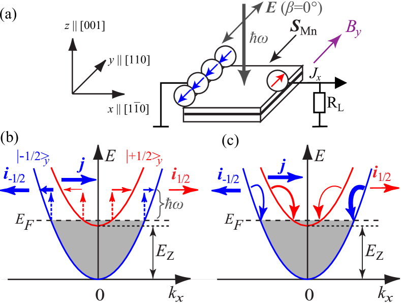
A straightforward mechanism causing the electric current is the unequal population of the spin subbands due to the Zeeman effect. The mechanism is sketched in Figs. 1(b) and 1(c) for the scattering-assisted optical excitation (excitation mechanism) and relaxation (relaxation mechanism), respectively. In the case of photoexcitation, Fig. 1(b), the transition rate in each spin subband depends on the subband population . Consequently, the electron fluxes in the spin subbands become unequal resulting in the electric current
| (2) |
where is the average electron spin projection along . For a low degree of spin polarization, it is given by
| (3) |
Here, is the Zeeman splitting energy and is the characteristic electron energy, equal to the Fermi energy for degenerate two-dimensional electron gas (2DEG) and for non-degenerate gas at the temperature , respectively. For linearly polarized radiation, photoexcited carriers are preferably aligned along the radiation electric field. Therefore, for a fixed magnetic field direction, e.g., , the polarization plane rotation, described by the azimuth angle, results in oscillations of the and current components as a function of . Similarly, the Zeeman splitting gives rise to an electric current in the case of energy relaxation of hot electrons. Of course, the latter mechanism, which is based on electron gas heating, is independent of the radiation polarization. Microscopic and symmetry analysis show that it results in a current along the -direction for . For (001)-oriented QWs, the polarization dependences of the total transverse, , and longitudinal, , photocurrents are given by (see Appendix)
| (4) |
where , and are polarization independent parameters, describing the relaxation mechanism () and excitation mechanism ( and ), is the azimuth angle ( for ), and and are the Cartesian coordinates. Note that while the direction of the polarization-independent current is determined by the magnetic field direction, QW crystallographic orientation and design, the directions of the polarization-dependent components can be varied just by rotation of the polarization plane.
In diluted magnetic semiconductors, the considered mechanism of the photocurrent generation is drastically enhanced due to the giant Zeeman splitting. In -type DMS structures, the splitting is given by the sum of intrinsic and exchange contributions Fur88
| (5) |
where is electron (hole) Lande factor in the absence of magnetic impurities, is the Bohr magneton, is the effective average concentration of Mn, is the exchange integral for conduction (valence) band carriers, is Mn -factor, is the Mn-spin system temperature. Parameters and account for the Mn-Mn antiferromagnetic interaction, and is the modified Brillouin function.
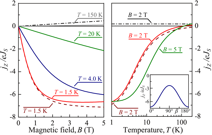
Shown in Fig. 2 are magnetic field and temperature dependences of the photocurrent calculated after Eqs. (2), (3) and (5) taking into account literature values of parameters for n-(Cd,Mn)Te QWs. In order to focus on the effect of magnetic impurities we normalized the current by the pure spin current , which depends on particular scattering mechanism and, therefore, may depend on temperature. At low temperatures, the current is dominated by the exchange interaction between free electrons and magnetic ions following the Brillouin function. As a result, the current first linearly grows with the magnetic field strength and then saturates. The increase in temperature leads to the decrease of the current magnitude and shifts the saturation to higher fields. Finally, at high temperatures, the exchange contribution to the Zeeman splitting becomes comparable or even smaller than the intrinsic one. In CdTe, where the sign of the intrinsic -factor is opposite to the exchange one Wojtowicz99 . This interplay results in a change of the photocurrent sign, see Fig. 2. In some other materials, e.g, -type (In,Ga)As:Mn DMS structures, both contributions have the same sign spinbook and inversion does not occur.
Equation (3) yielding the linear relation between the average electron spin and the Zeeman splitting is valid for a low degree of electron gas polarization only. This regime is relevant for the majority of structures at moderate magnetic fields of several Tesla. However, in DMS structures, where high degree of spin polarization can be achieved at moderate magnetic fields, the linear relation can be violated. This is another reason for the current saturation with rising the magnetic field. Indeed, in a fully spin-polarized electron gas, which can occur at low temperatures in DMS for magnetic fields even well below saturation of magnetization, the electron flux in one of the spin subbands vanishes. Therefore, the electric current becomes independent of the Zeeman splitting and is given by , where the sign is determined by the effective -factor sign.
The described variation of the photocurrent with temperature and magnetic field is relevant for both the excitation and relaxation mechanisms sketched in Fig. 1. However, an effective way to distinguish between these microscopically different mechanisms is to study the polarization dependence of the photocurrent. Indeed, for a fixed magnetic field, the excitation related photocurrent varies upon rotation the radiation polarization plane, see Eqs. (4), while the relaxation related current does not. An example of the dependence of the current containing both contributions on the azimuth angle is shown in the inset in Fig. 2(b).
So far, we have considered mechanisms of the spin polarized current formation based on the Zeeman splitting of electron spin subbands. However, there is an additional contribution to the photocurrent generation being specific for DMS structures. It is related to the spin-dependent electron scattering by polarized Mn2+ ions, which is described by the Hamiltonian of interaction between band electrons and magnetic ions Fur88
| (6) |
Here the index enumerates Mn ions, is the ion spin operator, is the electron spin operator, is the scattering potential without exchange interaction, the electron coordinate, and the ion position. Note that the parameter in Eq. (6) is also responsible for the giant Zeeman splitting in Eq. (5).
The external magnetic field polarizes the Mn spins leading to different scattering rates for band electrons with the spin projection along the ion polarization Egues . Accordingly, the momentum relaxation times in the spin subbands and become unequal. Since the electron fluxes depend on the momentum relaxation times in the spin subbands, they do not compensate one another giving rise to a net electric current . This photocurrent can occur even for equally populated spin subbands and, therefore, is superimposed on the Zeeman splitting related contribution . An estimation for can be made assuming that the momentum relaxation of electrons is determined by their interaction with Mn2+ ions. Taking into account the fact that the spin independent part of the Mn potential, characterized by , is usually much larger than the exchange term described by , we obtain
| (7) |
where is the electron momentum relaxation time for the case of non-polarized ions, is the average Mn spin projection along , , and is formally considered as a function of . Similarly to the current caused by the giant Zeeman splitting, the scattering related current (7) is determined by the Mn ions polarization and, therefore, is characterized by non-linear magnetic field dependence vanishing at high temperatures.
For a low degree of electron gas polarization, the photocurrent is given by the sum of two contributions
| (8) |
Due to the fact that both terms are caused by the exchange interaction, the resulting electric current will follow the Brillouin function no matter which contribution dominates. Depending on the structure material the currents and may interfere in constructive or distractive ways footnote0 . Possible ways to distinguish the relative contributions of and to the total spin-polarized electric current are to compare the temperature behavior of the current with that of the Zeeman splitting or to study the dependence of the current on the radiation frequency and structure mobility.
Finally we note, that at high temperatures, where the exchange enhancement of the current is absent, additional orbital mechanisms may contribute to the magnetic field induced photocurrent. The orbital contribution comes from an asymmetry in the electron scattering due to the Lorentz force acting upon carriers Tarasenko08 ; Tarasenko11 . Its sign depends on the QW design and scattering mechanism. Therefore, the interplay of spin and orbital mechanisms may influence the current behavior, e.g., results in shifting the temperature inversion point or even its appearance/disappearance. The orbital contribution to the photocurrent may also show up at low temperatures and high magnetic fields. Being linear in the magnetic field, it may lead to a deviation of the field behavior of the measured current from the Brillouin function expected for the exchange mechanism.
III III. Experimental technique
The experiments have been carried out on three different types of DMS low-dimensional structures with Mn2+ as the magnetic impurity. Here, spin-polarized photocurrents have been studied in the well known II - VI and III - V DMS systems, represented by -type (Cd,Mn)Te/(Cd,Mg)Te QWs and -type (In,Ga)As/InAlAs:Mn QWs, respectively, as well as in heterovalent hybrid II - VI/III - V -type AlSb/InAs/(Zn,Mn)Te QWs with Mn layers inserted into the II - VI barriers. All structures have been grown by molecular-beam epitaxy on semi-insulating (001)-oriented GaAs substrates with buffer layers corresponding to each material group in order to relax strain.
A set of mm2 sized samples from the quantum well structures having various density and spatial position of Mn-doping layers have been prepared. To measure the photocurrent two pairs of ohmic contacts at the center of the sample edges oriented along the and directions have been prepared [see inset in Fig. 4(b)]. The specific structures design and parameters are given in the beginning of the corresponding sections presenting the experimental results (see Sec. IV A-C). The samples were placed into an optical cryostat with -cut crystal quartz windows and split-coil superconducting magnet. The magnetic field B up to 7 T was applied in the QWs plane along axis. The sample temperature was varied from 1.8 up to 200 K.
The experimental geometry is sketched in Fig. 4(b). The measurements of magnetic-field-induced photocurrents are carried out under excitation of the (001)-grown QW samples with linearly polarized terahertz and microwave radiation at normal incidence. The experimental arrangement is chosen to exclude any effects known to cause photocurrents at zero magnetic field Ganichev02 . For optical excitation we use four different types of radiation sources: low power optically pumped CH3OH THz laser, Gunn diodes, backwards wave oscillator and high power pulsed optically pumped THz laser. The sources provided monochromatic radiation in the frequency range between 0.1 and 2.5 THz (corresponding photon energies, varied from 0.3 up to 10 meV). The radiation photon energies are smaller than the band gap as well as the size-quantized subband separation. Thus, the radiation induces indirect optical transitions in the lowest conduction subband (Drude-like free-carrier absorption).
Low power excitation with mW at the sample spot is obtained by the CH3OH THz laser emitting radiation with frequency THz (wavelength m) Kvon08 , backwards wave oscillator (Carcinotron) operating at GHz ( mm) and a Gunn diode with GHz ( mm). The incident power of the sources was modulated between 255 and 800 Hz by a pin switch (Gunn diode) or an optical chopper. The photocurrent is measured across a 1 M load resistor applying the standard lock-in technique. Pulsed high power THz radiation with THz (m), a peak power 40 kW at the sample spot, and a pulse duration of 200 ns is obtained by a NH3 laser optically pumped with a TEA CO2 laser physicaB99 ; Schneider2004 . In this set-up the signal is detected via a voltage drop over a 50 load resistor applying a fast amplifier and a storage oscilloscope. The radiation power has been controlled by either pyroelectric detectors or THz photon drag detector. The radiation is focused onto samples by one or two parabolic mirrors (for lasers and Carcinotron, respectively) or horn antenna (Gunn diode). Typical laser spot diameters varied, depending on the wavelength, from 1 to 3 mm. The spatial beam distribution had an almost Gaussian profile, checked with a pyroelectric camera. The spatial distribution of the microwave radiation at the sample’s position, and, in particular, the efficiency of the radiation coupling to the sample, by, e.g., the bonding wires and metalization of contact pads, could not be measured. Thus, all microwaves data are given in arbitrary units. In order to vary the angle between the light polarization plane and the magnetic field, the plane of polarization of the radiation incident on the sample was rotated by means of -plates. Hereafter, the angle = 0∘ is chosen in such a way that the incident light polarization is directed along the -axis, see inset in Fig. 4(b).
IV IV. Photocurrent experiments
In the following Sections (A-C) we present the experimental results for three different groups of DMS low dimensional structures. The sections are organized in a similar way; we start with the description of the structures design/parameters, than present a detailed study of the photocurrent behavior upon variation of the magnetic field strength, temperature, radiation intensity and polarization, and, finally give a comparison of the results with the theory described in Sec. II.
IV.1 A. -(Cd,Mn)Te/(Cd,Mg)Te quantum wells
Low dimensional structures based on wide band gap II-VI diluted magnetic semiconductors are the best understood DMS materials with the most studied electric and magnetic properties DMS2010 , and it is the DMS system in which the terahertz radiation induced spin-polarized electric current has been reported PRL09 ; Drexler10 . The experiments presented below have been carried out on 10 nm wide -type (Cd,Mn)Te single QWs embedded in (Cd,Mg)Te barriers. The DMS QWs were grown by molecular-beam epitaxy on (001)-oriented GaAs substrates Egues ; Crooker ; Jaroszynski2002 . Three groups of -(Cd,Mn)Te/Cd0.76Mg0.24Te structures with different Mn contents (A0, A1 and A2) were fabricated. In each group several samples from the same wafer were investigated. In the following we discuss the data obtained on the non-magnetic reference QWs (samples A0) and DMS QWs (with A0, A1 and A2 samples, discussed later being, the representative of each of those groups) having different magnetic properties. In samples A1 and A2 several evenly spaced Cd1-xMnxTe thin layers were inserted during the growth of the 10 nm wide QW applying the digital alloy technique Kneip2006 . In those samples the spin splitting can be described using Eq. (5).
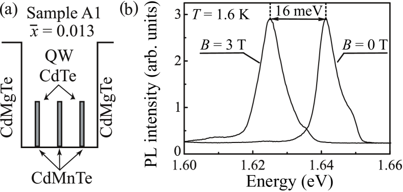
The sketch of sample A1 with three single monolayers of Cd0.86Mn0.14Te is shown in Fig. 3(a). Sample A2 has similar design but is fabricated with two insertions of three monolayers of Cd0.8Mn0.2Te. In the II-VI semiconductor compound the Mn atoms substitute the Cd atoms and providing a localized spin . In order to obtain a two-dimensional electron gas the structures have been modulation doped by Iodine donors introduced into the top barrier at 15 nm distance from the QW. The electron density, , and mobility, , obtained by magneto-transport measurements, as well as the effective average concentration of Mn and the Fermi energy , estimated from the photoluminescence (PL) spectra, are summarized in Table 1. PL spectra obtained from sample A1 at and 3 T are shown in Fig. 3(b). Here the line for T is substantially red-shifted (about 16 meV at K) relative to that for zero field. This shift corresponds to 32 meV giant Zeeman splitting of band states from which 6.4 meV fall into conduction band Fur88 .
| sample | , cm2/Vs | , cm-2 | , meV | ||
|---|---|---|---|---|---|
| A0 | 0 | 0 | 59000 | 4.2 | 10.4 |
| A1 | 0.14 | 0.013 | 16000 | 6.2 | 15.4 |
| A2 | 0.20 | 0.015 | 9500 | 4.7 | 11.7 |
We start by describing the results obtained with low power THz and mw sources. The signal in unbiased samples is observed under normal incidence with linearly polarized radiation for both transverse and longitudinal geometries, where the current is measured in the direction perpendicular, , and parallel, , to the magnetic field , respectively footnote . Figure 4 shows magnetic field dependence of the transverse photocurrent . The detected photocurrent is an odd function of the magnetic field: It increases with raising magnetic field strength, vanishes for and its sign depends on the magnetic field direction. The signal linearly scales with the radiation power and does not show a hysteretic behavior as ensured by sweeping magnetic field from positive to negative fields and back (both not shown). For convenience, in the discussion below we evaluate the data after
| (9) |
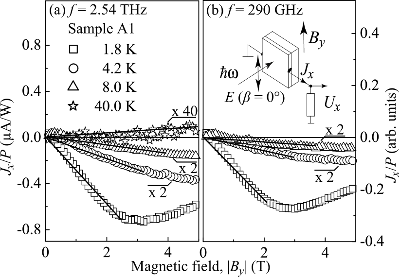
which yields solely the strength of the magnetic field induced photocurrent. Characteristic dependences of the photocurrent upon variation of temperature, magnetic field strength, radiation wavelength, intensity and polarization are the same for all samples within each group and are qualitatively the same for all DMS samples belonging to A1 and A2 groups. Thus, below we consistently present the data obtained on one of the A1 sample. Figures 4(a) and 4(b) show the magnetic field dependence of the transverse photocurrent measured in sample A1 under excitation with THz radiation ( THz) and mw radiation ( GHz), respectively. The experiments reveal that at high temperatures, or at low temperatures and moderate magnetic fields, the magnitude of is proportional to , see Ref. [footnote2, ]. At low temperatures and high magnetic fields, however, the photocurrent saturates with increasing . Moreover at K a small reduction of signal with increasing magnetic field is observed for T.
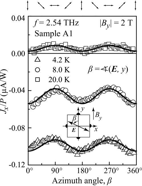
Figure 5 shows the polarization dependence of the photocurrent measured in DMS sample A1 excited by THz radiation. The data are obtained for T at which the photocurrent does not show a saturation in the whole temperature range, see Fig. 4(a). Consequently, the signal behavior upon variation of the azimuth angle or temperature is not affected by the photocurrent saturation. The current is well described by the first equation of Eqs. (4), see also inset in Fig. 2(b), and consists of a polarization-independent, , and polarization dependent, , components. Following Eq. (4) the individual contributions to the transverse photocurrent, and , can be deduced from the experiment by taking, respectively, a half-sum or a half-difference of the signals obtained at and . In the longitudinal configuration we detected only the polarization-dependent photocurrent well described by the second equation of Eqs. (4).
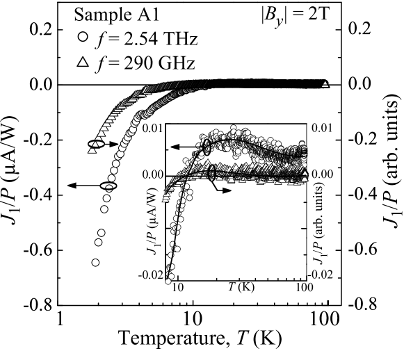
The most striking observation comes from the investigation of the temperature dependence of the polarization independent photocurrent . Figure 6 reveals that a cooling of the sample from 100 K down to 1.8 K results in, on the one hand, a change of the current direction, and, on the other hand, an increase of the photocurrent strength by about two orders of magnitude. Such a temperature dependence is observed for both the THz and mw radiation induced photocurrents and the corresponding data differs by a scalar factor only, see Fig. 6. By contrast, in the reference non-magnetic sample A0, the drastic enhancement of the signal magnitude and the inversion of the photocurrent direction with the temperature decrease have not been observed (not shown).
The peculiar temperature behavior observed in DMS QWs excited by low power radiation dwindle under application of high power pulsed THz radiation with kW, see Ref. [footnote3, ]. While at low power excitation the photocurrent direction changes upon cooling and its magnitude strongly depends on the temperature (Figs. 4 and 6) the current induced by high power pulsed THz radiation neither undergoes an inversion nor exhibit a significant dependence on in the range between 1.8 and 100 K, see Fig. 7. Furthermore, irradiation with high power leads to a strong decrease of the magnitude of signal normalized by the radiation power, , compared to the one for low power data ( instead of ). Moreover, the photocurrent saturation with increasing magnetic field observed at low power disappears, and the signal excited by high power laser linearly scales with magnetic field strength, Fig. 7(a). It is also remarkable that now DMS samples and non-magnetic samples show the same temperature dependence: The photocurrent is almost independent of the sample temperature below about 100 K and decreases for K, see Fig. 7(b).
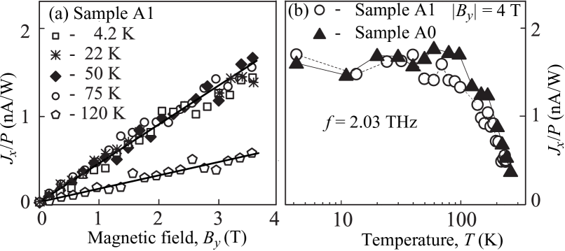
The experimental results described above are in a good agreement with the theory of radiation-induced spin-polarized electric currents in DMS quantum wells subjected to an in-plane external magnetic field, see Sec. II. Comparison of the photocurrent calculated after Eqs. (2) to (5) and shown in Fig. 2 , with the corresponding data, see Figs. 4 – 6, shows qualitative similarity of the theoretical and experimental results. In particular, the drastic enhancement of the photocurrent magnitude and the change of its direction upon samples cooling, as well as the observed saturation of the signal with raising magnetic field strength are clear consequences of the exchange interaction between the -type conduction band electrons and the half filled -shell of the Mn2+ ions. The observed photocurrent sign inversion upon temperature variation is caused by the opposite signs of the intrinsic and exchange Zeeman spin splittings, well known for these materials. Due to the strong dependence of the Brillouin function [see last term in Eq. (5)] on temperature sample heating results in the rapid reduction of the exchange part to the photocurrent and the dominance of the intrinsic one. The interplay of intrinsic and exchange -factors contributes also to the deviation from the saturation behavior observed at low temperatures. Here, instead of the saturation expected for the Brillouin function a slight decrease of the photocurrent at high magnetic fields is detected, see Fig. 4. Similar behavior is seen for the calculated photocurrent shown by the solid lines in Fig. 2(a), where both extrinsic and intrinsic contributions are taken into account, see Ref. [footnote3a, ].
While for low power radiation the heating of the sample or the manganese system plays no essential role and the signal linearly scales with radiation intensity a substantial increase of the radiation power qualitatively changes the photocurrent formation. Indeed, in the high power experiments neither an inversion nor a photocurrent enhancement by cooling down the sample have been observed, see Fig. 7. This indicates that at these conditions the polarization of the Mn2+ spins does not contribute to the generation of current. Figure 7 demonstrates that the photocurrent in DMS samples excited by high power radiation is at all temperatures proportional to the magnetic field and varies with temperature in the same manner as the one measured in non-magnetic reference sample A0. It can be well described with Eqs. (2), (3), and (5) assuming vanishing contribution of the exchange interaction. For low temperatures and degenerated electron gas the characteristic electron energy is equal to and the photocurrent is nearly independent of . In the case of a non-degenerated gas (higher temperatures) is given by and leads to a dependence of . These two regimes are clearly pronounced in Fig. 7(b) and, in fact, are well known for spin-polarized photocurrents in non-magnetic semiconductor structures Nature06 ; Belkov2008 .
The observed photocurrent variation with the orientation of the radiation polarization plane is also in agreement with the theory developed in Sec. II. The polarization dependence of the transverse photocurrent shown in Fig. 5 is in agreement with Eq. (4) and corresponding calculated curve shown in the inset in Fig. 2(b). It demonstrates that this current is a result of superposition of the polarization-independent current due to energy relaxation of hot electrons described by in Eqs. (4) (relaxation contribution) and the polarization-dependent one due to excitation given by the second term in the first equation in Eqs. (4). The longitudinal photocurrent is also observed and its polarization dependence is in agreement with the second equation in Eqs. (4).
The interplay of the giant exchange Zeeman splitting and the intrinsic one in the total spin splitting explains qualitatively the behavior of the photocurrent upon changing magnetic field strength, temperature, Mn doping as well as radiation intensity and polarization. However, the observed increase of the current strength at low temperatures is substantially larger than the giant Zeeman shift measured in the same structures by the photoluminescence data. For example in sample A1 at T the spin splitting, derived from PL data, changes from meV at high temperatures (intrinsic value given by ) to 2.6 meV at 4.2 K and, hence, its magnitude swells by about a factor 10. By contrast, the magnitude of the photocurrent at K increases by about factor of 100 compared to that measured for K, see Fig. 4(a). This quantitative disagreement together with the strong temperature dependence of the signal provide an evidence for the dominating contribution of another DMS specific mechanism. This is the spin current due to the spin-dependent electron scattering by polarized Mn2+ ions which was elaborated at the end of Sec. II and is shown to amplify the current conversion vastly.
IV.2 B. Mn-doped -(In,Ga)As/InAlAs quantum well structures
The second type of investigated samples III – V based DMS, with Mn as the magnetic impurity, are studied to a less extent than the principal II – VI DMS family, but are already well understood DMS2010 . Currently this type of DMS structures are intensively studied because of their prospect for spin-polarized carrier injection Ohno2010 ; Dietl2010 ; FlatteNature2011 ; Kohda06 required for spintronics applications. In III – V semiconductors, like InAs or GaAs, Mn atoms substitute the group III elements (In, Al or Ga), providing both localized magnetic moments with spin and free holes Dietl , in contrast to II – VI materials, where Mn is an isoelectric impurity.
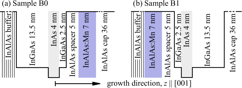
Samples investigated in the present work are compressively strained InAs quantum wells embedded in (In,Ga)As/InAlAs:Mn host material with an In mole fraction of 75% (for details, see Ref. [Wurstbauer09b, ]) High mobility Mn modulation-doped single QW structures were grown by molecular-beam epitaxy on semi-insulating GaAs (001)-oriented substrates. The layer sequences of two fabricated Mn-doped samples are depicted schematically in Fig. 8. The active layer consists of a 20 nm In0.75Ga0.25As channel with an additional strained 4 nm InAs QW, a 5 nm thick In0.75Al0.25As spacer, a 7 nm thick Mn doped In0.75Al0.25As layer, and a 36 nm In0.75Al0.25As cap layer. The samples differ in the position of the Mn-doped layer. In the ‘normal’ sample B0, see Fig. 8(a), a 5 nm In0.75Al0.25As spacer followed by the Mn doping layer was grown after the InAs/InGaAs channel, so that the InAs QW is free of Mn Prechtl03 ; Wurstbauer09 . In this sample the InAs QW is located 2.5 nm away from the channel border, it is facing the Mn site and is separated from Mn layer by 7.5 nm. The hole density and mobility obtained by magneto-transport measurements are cm-2 and cm2/Vs. In the ‘inverted’ doped structures B1, see Fig. 8(b), the Mn-doped layer is also separated from the InAs QW by 7.5 nm but is deposited before the channel growth. Due to segregation this growth leads to a significant concentration of Mn ions in the InAs QW. The hole density in this sample is cm-2 and the mobility is reduced by at least a factor of two compared to sample B0.
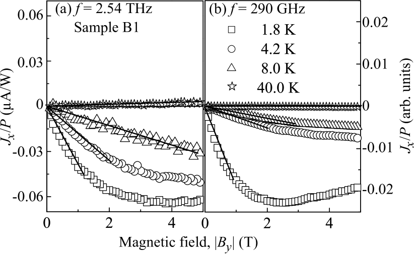
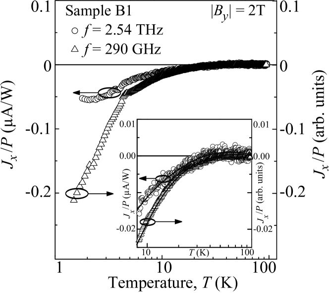
Figures 9 and 10 show the magnetic field and temperature dependences of the photocurrent generated in sample B1 under low power THz and mw excitation. These data reveal that the temperature decrease leads to a drastic enhancement of the photocurrent magnitude as well as it changes the linear in B dependence of the signal into a Brillouin-function-like saturation. footnote4 These results which are similar to that obtained in -type (Cd,Mn)Te DMS samples, are well described by Eqs. (2), (3), and (5), and provide a clear evidence for the exchange interaction based origin of the observed photocurrent. The inset in Fig. 10 demonstrate that for mw-excitation raising temperature does not result in the inversion of the current direction. This result is expected for -type InAs DMS structures, in which, in contrast to -type II-VI QWs, the intrinsic -factor for carriers and the exchange integral have the same sign. For terahertz excitation a tiny positive photocurrent is observed for K, which we attribute to the interplay of the negative intrinsic spin photocurrent and positive orbital photocurrent Tarasenko08 . Orbital photocurrent may also be responsible for a weaker temperature dependence of the THz radiation induced photocurrent compared to the one excited by mw radiation. The photocurrent excited in the normal Mn-doped sample B0, by contrast, is vanishingly small and we do not observe any substantial increase of its magnitude upon sample cooling. For both samples the signal is almost independent of the orientation of the radiation plane. This observation demonstrates that the photocurrent is dominated by the relaxation mechanism.
Experiments applying high power pulsed THz laser radiation to both B0 and B1 samples reveal that, similarly to the data obtained for -type (Cd,Mn)Te DMS samples [Fig. 7(a)], at all temperatures the signal linearly increase with raising magnetic field. Also the temperature dependence is very similar to that detected in -type (Cd,Mn)Te DMS samples [Fig. 7(b)]. The same results are obtained for the non-magnetic reference n-type InAs QW sample doped by Si excited by high power THz light as well by low power THz and mw radiation. All these observations are in a good agreement with the theory of spin-polarized photocurrents in non-magnetic semiconductor structures, see Sec. II.
While it was clearly observed in sample B1 at low power excitation, at the first glance, the Mn doping outside of the conducting channel should not result in a magnetic behavior, because the wave function of the carrier does not penetrate to the Mn location. However, the B1 sample is doped on the substrate side and the Mn atoms penetrate towards the conducting channel due to segregation of Mn atoms during the structure growth. The segregation results in the presence of Mn2+ ions in the vicinity of the two-dimensional hole gas. The enhanced magnetic properties manifest themselves by the colossal negative magnetoresistance and the associated field-induced insulator-to-metal transition observed in such structures Wurstbauer10 . By contrast, in the -type InAs QW sample with Mn doping on the surface side (sample B0) the segregation shifts the Mn atom distribution away from the 2D channel and the giant Zeeman splitting of the hole subbands in InAs QWs is almost absent. The absence of the giant Zeeman splitting in sample B1 substantiates the absence of residual Mn2+ ions in close vicinity to the two-dimensional hole gas. This further verifies the interpretation of earlier magnetotransport experiments Wurstbauer09b .
Similarly to II – VI DMS samples A1 and A2 we observed that in the inverted sample B1 the magnitude of the photocurrent measured at 1.8 K is about two orders of magnitude larger than that at 40 K. Such enhancement is larger than that expected for the giant Zeeman spin splitting and provides an indirect evidence for the substantial contribution of the photocurrent due to scattering by magnetic ions. However, the direct comparison of the current variation to the Zeeman spin splitting is impossible, because no PL or time-resolved Kerr rotation data for the InAs-based QWs are in our disposal.
IV.3 C. Heterovalent n-AlSb/InAs/ZnMnTe quantum wells
InAs based DMS structures are usually characterized by p-type conductivity Wurstbauer09b ; ohno1992 . Concerning n-type In(Mn)As DMS only thin films and superlattices with mobilities in the order of 100 to 1000 cm2/Vs have been reported so far Munekata89 ; Soo1996 ; Acbas ; Munekata03 . The realization of n-type InAs based DMS QWs with high mobility and controllably exchange interaction remains an important issue. A possible way to achieve this goal is to extend the heterovalent growth technology by the doping with magnetic ions. While III-V and II-VI DMS systems are widely studied and their magnetic properties are well known, heterovalent n-type AlSb/InAs/ZnMnTe quantum wells are new in the DMS family. These structures combine a narrow gap III – V QW with wide gap II – VI barriers Ivanov04 . Manganese is introduced into the ZnTe barrier where it substitutes Zn and keeps electrically neutral providing a localized spin . The enhanced magnetic properties are caused by the penetration of electron wave function of two-dimensional electrons into the (Zn,Mn)Te layer and can be controllably varied by the position and concentration of Mn2+ ions Terentjev11 .
To fabricate AlSb/InAs/(Zn,Mn)Te heterovalent structures with Mn-containing barriers two separate MBE chambers have been applied, one for the III – V and the other for the II – VI part. In the III – V MBE machine a buffer layer of GaSb containing a strained AlSb/GaSb superlattice was grown. It follows by a 4 nm thick AlSb barrier and a 15 nm thick InAs QW.
Before the first III – V part was transferred to the II – VI MBE setup the structure was passivated ex situ by sulfur exchanging a surface oxide, which then could be easily removed to start a coherent growth of ZnTe on top of InAs. In order to obtain a diluted magnetic semiconductor barrier of InAs QW, sample C1, a 1 ML ( 0.32 nm) MnTe was introduced into the ZnTe barrier at a 10 ML distance from the QW. By that, as a result of the segregation and diffusion processes, we obtain structure with Mn ions distributed over several monolayers of the surrounding ZnTe. The maximum content of the remaining MnTe is estimated to be well below 30 mol.. Structure C2 has the same spacer with an adjacent 10 nm Zn0.9Mn0.1Te layer of lower Mn concentration per ML. Sample C0 is a reference structure with non-magnetic ZnTe barrier.
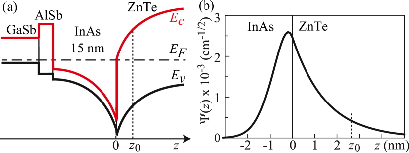
The two-dimensional electron gas has the density 1013 cm-2 and the mobility 103 cm2/Vs at K. The most of 2D electrons in hybrid QW originate from donor centers located at III – V/II – VI heterovalent interface resulting in the large surface density of positively charged donor centers at the interface, while the Fermi level within the InAs layer is pinned to that in the GaSb and ZnTe layers. Consequently, the structures become highly asymmetric due to a strong built-in electric field. The band structure of the sample C1 is sketched in Fig. 11(a).
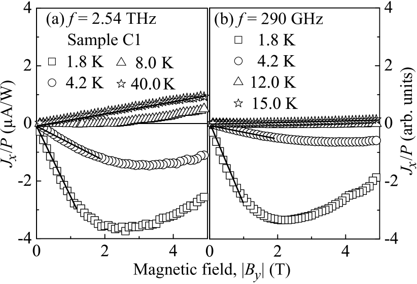
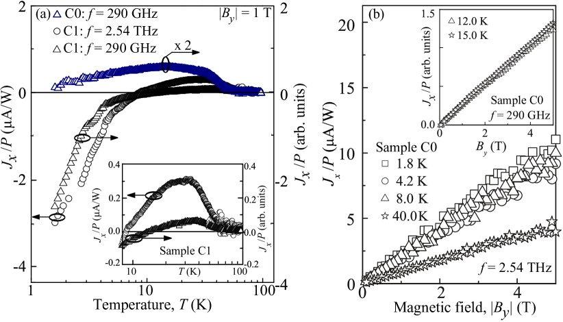
The magnetic field and temperature dependences of the photocurrent induced in the DMS sample C1 are shown in Figs. 12 and 13(a), respectively. Both plots demonstrate the characteristic influence of Mn2+ ions aligned by the external magnetic field. The sign inversion of the photocurrent and the strong enhancement of its magnitude by cooling the sample as well as the non-linear magnetic field behavior (saturation at high ) are clearly observed. footnote5 The picture remains qualitatively the same for both low power THz and mw radiations. The only difference is the value of the inversion temperature which is about 15 K for mw radiation induced photocurrent and about 9 K for THz photocurrent. Figure 13 also shows the data for the reference non-magnetic AlSb/InAs/ZnTe QW sample C0. Here, in contrast to the sample C1, the photocurrent shows linear dependence on the external magnetic field in the whole temperature range, it does not depend substantially on temperature for K and for K decreases as . In sample C2 with Zn0.9Mn0.1Te inserted in the barrier and distributed over a larger distance from QW we observed less pronounced DMS properties (not shown). The photocurrent changes its sign upon cooling the samples at K, but at low temperature its magnitude is substantially lower than that detected in sample C1.
All these findings give a strong evidence for a substantial influence of the exchange coupling between the 2D electrons and the Mn atoms introduced in the ZnTe barrier in sample C1 and less pronounced effect of magnetic impurities in the sample C2. In both magnetic samples C1 and C2 (Fig. 11) the Mn layers are separated from the QW by 10 ML thick spacer. Therefore the exchange interaction is supposed to be mediated via a penetration of the electron wave function into the barrier. Meilikhov_2010 The Zeeman splitting in structures with Mn ions -layer placed at can be estimated using the standard expression
| (10) |
where is the sheet Mn density. The necessary overlap of the electron envelope wave function with Mn2+ ions is ensured by the strong asymmetry of the QWs due to the built-in electric field discussed above. The calculations prove that the wave function deeply penetrates into ZnTe resulting in the substantial overlap of and Mn2+ ions in C1 structure, see Fig. 11(b). Due to the opposite signs of in InAs and , under sample cooling the sign of inverses resulting in the reversion of the photocurrent direction as observed for C1 structure, see Figs. 12 and 13, and as well as for C2 samples. In the sample C1 with Mn -layer the current behavior at low temperature is dominated by the exchange interaction and almost follows the Brillouin function: it is amplified by cooling the sample and, at low temperatures, saturates with raising magnetic field [see Figs. 12 and 13(a)]. Estimations of the Zeeman spin splitting in sample C1 made after Eq. (10) using cm-2 and meV cm3, see Ref. [Twardovski, ], show that at K and T exchange spin splitting should be one order of magnitude larger than the intrinsic Zeeman splitting. This estimated value agrees well with experimental findings, see Fig. 13(a), and indicates that the Zeeman splitting based mechanism dominates the current formation.
The photocurrent data obtained on the sample C2 show much less pronounced magnetic properties and give a further support of the suggested mechanism for exchange interaction in C-type DMS structures. Indeed, because of spatial distribution of the Mn over larger distance from QW, in sample C2 the overlap of the electron wave function with the Mn2+ ions should be substantially smaller than that in C1 structure.
V V. Summary
In summary, we demonstrate that the irradiation various types of low-dimensional diluted magnetic semiconductors by low power terahertz or mw radiation causes spin-polarized electric current if in-plane magnetic field is applied. Microscopically, the effect originates from the spin-dependent asymmetric scattering of carriers resulting in a pure spin current which is converted into a spin-polarized electric current by magnetic field. Furthermore, its behavior clearly reflects all characteristic features of the exchange interaction and is giantly enhanced at low temperatures. The spin-polarized electric current enhancement is caused by the exchange interaction of carriers with Mn2+ ions resulting in the giant Zeeman splitting. In the structures with the Mn2+ ions in the quantum well the efficiency of the current generation is additionally amplified due to the spin-dependent scattering of carriers by polarized Mn2+ ions. Our measurements carried out on II – VI, III – V and hybrid II – V/II – VI QW structures doped by Mn demonstrate that the effect is very general and can be used for the efficient generation of spin-polarized electric currents, e.g., applying conventional Gunn diodes, as well as for the study of DMS materials. The latter could be of particular importance for exploring DMS properties in materials hardly accessible by optical or transport measurements.
Acknowledgements.
The financial support from the DFG (SFB 689), the Linkage Grant of IB of BMBF at DLR, RFBR, RF President grant MD-2062.2012.2, and the Foundation “Dynasty” is gratefully acknowledged. The research in Poland was partially supported by the EU within European Regional Development Found, through grant Innovate Economy (POIG.01.01.02-00-008/08).VI Appendix. Calculation of electron fluxes in the spin subbands
Here we derive analytical equations for the electron fluxes in the spin subbands. We consider the excitation mechanism which is responsible for polarization-dependent spin current. In the framework of kinetic theory, the fluxes are given by
| (11) |
where , is the electron velocity, is the effective mass, and is the electron distribution functions in the spin subband.
VI.1 A. Quasi-classical theory
For low-frequency electromagnetic field, , the distribution functions of carriers in the spin subbands can be found from the Boltzmann equation
| (12) |
where is the electric field of radiation in QW, is the (complex) field amplitude, and is the collision integral. In the case of spin-conserving elastic scattering of electrons by impurities or structure defects, the collision integral has the form
| (13) |
where is the scattering rate in the spin subband, is the matrix element of scattering, , and the angle brackets denote averaging over scatterers. Taking into account -linear contributions to the matrix element of scattering Eq. (1), one obtains, e.g., for the spin projections onto the axis,
| (14) |
It is assumed in Eq. (14) that the matrix elements and are real, , and and are the only non-zero components of the tensor in (001)-grown QWs. Below we suggest that the scattering asymmetry is caused by short-range impurities or defects and, therefore, is independent of the directions of the wave vectors and .
To solve kinetic Eq. (12) we expand the distribution functions in series of powers of the electric field,
| (15) |
where is the equilibrium distribution functions of electrons in the spin subband, , and . The first order corrections to the equilibrium distribution function oscillate at the radiation field frequency and do not contribute to dc fluxes. The directed fluxes in the spin subbands are determined by the second order in corrections and obtained by multiplying by the velocity and summing up the result over the momentum, see Eq. (11). Such a procedure yields
| (16) | |||||
where
| (17) |
| (18) |
| (19) |
where and are the relaxation times of the first and second angular harmonics of the distribution function,
is the angle between and , and . The fluxes and are directed oppositely to each other forming a pure spin current for equal distribution functions in the spin subbands and equal scattering rates.
It follows from Eqs. (16)-(19) that the fluxes depend on the radiation polarization state. For linearly polarized radiation, the dependence of the and components on the azimuth angle is given by Eq. (4) because and for the experimental geometry used. The term proportional to in Eq. (16) describes the contribution to spin current that is sensitive to the sign of radiation helicity. It can be excited by circularly or, in general, elliptically polarized radiation and reversed by changing the sign of circular polarization. Equation (19) shows that the helicity-sensitive current in QWs emerges due to the energy dependence of the momentum relaxation time. If electrons are scattered by short-range impurities or defects, then the energy dependence of and can be neglected, , and the parameter takes the form
| (20) |
while and vanish. In this case, the excitation mechanism leads only to the current contribution which is sensitive to the linear polarization of radiation. The polarization independent fluxes in the spin subbands are completely determined by the energy relaxation mechanism.
VI.2 B. Quantum theory
The presented above quasi-classical approach is not valid if the photon energy is comparable or exceeds . In this spectral range, an adequate microscopic theory of spin current generation can be developed in the framework of quantum consideration of intrasubband optical transitions in QW. Such transitions are accompanied by electron scattering by impurities, acoustic or optical phonons, etc., because of the need for energy and momentum conservation. To first order in spin-orbit interaction, the matrix element of optical transitions in the subbands with the spin projection along accompanied by elastic electron scattering from short-range impurities has the form Nature06 ; Tarasenko06
| (21) |
where is the vector potential of the electromagnetic wave and is the speed of light. The first term on the right-hand side of Eq. (21) describes transitions with intermediate states in the conduction subband , the second term corresponds to the transitions via intermediate states in other bands.
We assume that the radiation frequency is high enough, . Then, the distribution functions of electrons in the spin subbands satisfy the kinetic equation
| (22) |
where is the optical generation rate,
| (23) |
and is the collision integral given by Eq. (13). Taking into account spin-dependent terms in the generation rate and the collision integral one can calculate the distribution functions and then, using Eq. (11), the fluxes . Such a calculation yields
| (24) | |||||
where is a dimensionless parameter that depends on the carrier distribution,
and is equal to 1 and 2 for the cases and , respectively. We note that, in the frequency range , both the quasi-classical theory Eqs. (16) and (20) and the quantum theory Eq. (24) give the same result.
References
- (1) S. Maekawa, Concepts in Spin Electronics (Oxford University Press, Oxford 2006).
- (2) J. Fabian, A. Matos-Abiague, C. Ertler, P. Stano, and I. Zutic, Acta Phys. Slov. 57, 565 (2007).
- (3) Spin Physics in Semiconductors, Ed. M. I. Dyakonov (Springer, Berlin 2008).
- (4) Spintronics, Eds. T. Dietl, D. D. Awschalom, M. Kaminska, and H. Ohno, in Semiconductors and Semimetals, v. 82 (Elsevier, Amsterdam 2008).
- (5) M. W. Wu, J. H. Jiang, and M. Q. Weng, Phys. Reports 493, 61 (2010).
- (6) Semiconductor Spintronics and Quantum Computation eds. D. D. Awschalom, D. Loss, and N. Samarth (Springer, Berlin 2010).
- (7) Handbook of Spin Transport and Magnetism eds. E. Y. Tsymbal and I. Zutic (Tailor & Francis 2012).
- (8) Introduction to the Physics of Diluted Magnetic Semiconductors, Eds. J. Kossut and J. A. Gaj (Springer, Berlin 2010).
- (9) Handbook of Spintronic Semiconductors, eds. W. M. Chen and I. A. Buyanova (Pan Stanford Publishing 2010).
- (10) H. Ohno, Nature Materials 9, 952 (2010).
- (11) T. Dietl, Nature Materials 9, 965 (2010).
- (12) M. Flatte, Nature Physics 7, 285 (2011).
- (13) J. K. Furdyna, J. Appl. Phys. 64, R29 (1988).
- (14) S. D. Ganichev, V. V. Bel’kov, S. A. Tarasenko, S. N. Danilov, S. Giglberger, Ch. Hoffmann, E. L. Ivchenko, D. Weiss, W. Wegscheider, Ch. Gerl, D. Schuh, J. Stahl, J. De Boeck, G. Borghs, and W. Prettl, Nature Phys. 2, 609 (2006).
- (15) S. D. Ganichev, S. N. Danilov, V. V. Bel’kov, S. Giglberger, S.A. Tarasenko, E. L. Ivchenko, D. Weiss, W. Jantsch, F. Schäffler, D. Gruber, and W. Prettl, Phys. Rev. B 75, 155317 (2007).
- (16) J. Dai, H.-Z.Lu, C. L. Yang, S.-Q. Shen, F.-C. Zhang, and X. Cui, Phys. Rev. Lett. 106, 246601 (2010).
- (17) S. D. Ganichev, S. A. Tarasenko, V. V. Belkov, P. Olbrich, W. Eder, D. R. Yakovlev, V. Kolkovsky, W. Zaleszczyk, G. Karczewski, T. Wojtowicz, and D. Weiss Phys. Rev. Lett. 102, 156602 (2009).
- (18) E. L. Ivchenko and S. A. Tarasenko, Semicond. Sci. Technol. 23, 114007 (2008).
- (19) T. Wojtowicz, M. Kutrowski, J. Kossut, F. J. Teran, and M. Potemski, Phys. Rev. B 59, 10437 (1999).
- (20) J.C. Egues and J.W. Wilkins, Phys. Rev. 58, R16012 (1998).
- (21) Since the average electron spin due to the giant Zeeman effect is parallel to , the directions of currents and caused by the relaxation mechanism coincide for .
- (22) S. A. Tarasenko, Phys. Rev. B 77, 085328 (2008).
- (23) S. A. Tarasenko, Phys. Rev. B 83, 035313 (2011).
- (24) S. D. Ganichev, E. L. Ivchenko, and W. Prettl, Physica E 14, 166 (2002).
-
(25)
Z. D. Kvon, S. N. Danilov, N. N. Mikhailov, S. A. Dvoretsky, and S. D.Ganichev
Physica E 40, 1885 (2008). - (26) S. D. Ganichev, Physica B 273-274, 737 (1999).
- (27) P. Schneider, J. Kainz, S. D. Ganichev, V. V. Bel’kov, S.N. Danilov, M. M. Glazov, L. E. Golub, U. Rössler, W. Wegscheider, D. Weiss, D. Schuh, and W. Prettl, J. Appl. Phys. 96, 420 (2004).
- (28) C. Drexler, V. V. Bel’kov, B. Ashkinadze, P. Olbrich, C. Zoth, V. Lechner, Ya. V. Terent’ev, D. R. Yakovlev, G. Karczewski, T. Wojtowicz, D. Schuh, W. Wegscheider, and S. D. Ganichev, Appl. Phys. Lett. 97, 182107 (2010).
- (29) S. A. Crooker, D. A. Tulchinsky, J. Levy, D. D. Awschalom, R. Garcia and N. Samarth, Phys. Rev. Lett. 75, 505 (1995).
- (30) J. Jaroszynski, T. Andrearczyk, G. Karczewski, J. Wróbel, T. Wojtowicz, E. Papis, E. Kaminska, A. Piotrowska, D. Popovic, and T. Dietl, Phys. Rev. Lett. 89, 266802 (2002).
- (31) M. K. Kneip, D. R. Yakovlev, M. Bayer, G. Karczewski, T. Wojtowicz, and J. Kossut, Appl. Phys. Lett. 88, 152105 (2006).
- (32) We note that in the theoretical parts of the paper the current density is used while in experiment the electric current is measured, which is proportional to the current density.
- (33) At low magnetic fields T a small deviation from the linear coupling between and is detected, see Fig. 4. The magnitude of this feature depends on the contacts quality and, most probably, originates from the illumination of contacts. However, this spurious signal is small compared to that at high magnetic fields and will not be discussed in the following.
- (34) Note that the photocurrent pulses have typical duration of about 100 ns, which corresponds to the terahertz laser-pulses length.
- (35) An additional reason for this discrepancy could be a contribution of the orbital current Tarasenko08 ; Tarasenko11 , which, as discussed in Sec. II, is almost insensitive to the enhanced magnetic properties and is out of scope of this paper.
- (36) V. V. Bel’kov, P. Olbrich, S. A. Tarasenko, D. Schuh, W. Wegscheider, T. Korn, C. Schüller, D. Weiss, W. Prettl, and S. D. Ganichev, Phys. Rev. Lett. 100, 176806 (2008).
- (37) M. Kohda, T. Kita, Y. Ohno, F. Matsukura, and H. Ohno, Appl. Phys. Lett. 89, 012103 (2006).
- (38) T. Dietl, in Handbook on Semiconductors, Vol. 3b, Ed. T. S. Moss (North-Holland, Amsterdam 1994).
- (39) U. Wurstbauer and W. Wegscheider, Phys. Rev. B 79, 155444 (2009).
- (40) G. Prechtl, W. Heiss, A. Bonanni, W. Jantsch, S. Mackowski, and E. Janik, Phys. Rev. B 68, 165313 (2003).
- (41) U. Wurstbauer, M. Soda, R. Jakiela, D. Schuh, D. Weiss, J. Zweck, and W. Wegscheider, J. Cryst. Growth 311, 2160 (2009).
- (42) A small deviation from the saturation behavior seen for microwave data we attribute to the contribution of the orbital current discussed in Sec. II.
- (43) U. Wurstbauer, C. Sliwa, D. Weiss, T. Dietl, and W. Wegscheider, Nature Phys. 6, 955 (2010).
- (44) H. Ohno, H. Munekata, T. Penny, S. von Molnar, and L. L. Chang, Phys. Rev. Lett. 68, 2664 (1992).
- (45) H. Munekata, H. Ohno, S. von Molnar, A. Segmüller, L. L. Chang and L. Esaki, Phys. Rev. Lett. 63, 1849 (1989).
- (46) Y. L. Soo, S. W. Huang, Z. H. Ming, Y. H. Kao, H. Munekata, and L. L. Chang, Phys. Rev. B 53, 4905 (1996).
- (47) G. Acbas, G. B. Kim, X. Chen, S. Wang, M. Cheon, C. J. Meining, H. Luo, B. D. McCombe, Y. Sasaki, X. Liu, and J. K. Furdyna, Physica E 20, 382 (2004).
- (48) G. A. Khodaparast, M. A. Zudov, J. Kono, Y. H. Matsuda, T. Ikaida, S. Ikeda, N. Miura, T. Slupinski, A. Oiwa, H. Munekata, G. D. Sanders, Y. Sun, and C. J. Stanton, J. Supercond. 16, 107 (2003).
- (49) S. V. Ivanov, V. A. Kaygorodov, S. V. Sorokin, V. A. Solov’ev, A. A. Sitnikova, O. G. Lyublinskaya, Ya. V. Terent’ev, Yu. B. Vasilyev, V. L. Berkovits, A. A. Toropov, and P. S. Kop’ev, phys. st. sol. C 1, 1468 (2004).
- (50) Ya. V. Terent’ev, C. Zoth, V. V. Bel’kov, P. Olbrich, C. Drexler, V. Lechner, P. Lutz, A. N. Semenov, V. A. Solov’ev, I. V. Sedova, G. V. Klimko, T. A. Komissarova, S. V. Ivanov, and S. D. Ganichev Appl. Phys. Lett. 99, 072111 (2011).
- (51) Like in discussion of the results obtained for DMS samples of A and B type we attribute a deviation from the saturation behavior observed for high magnetic fields to the contributions of intrinsic and orbital photocurrents.
- (52) E. Z. Meilikhov and R. Z. Farzedinova, JETP 110, 794 (2010).
- (53) A. Twardowski, P. Swiderski, M. von Ortenberg, and R. Pauthenet, Sol. St. Comm. 50, 509 (1984).
- (54) S. A. Tarasenko, Phys. Rev. B 73, 115317 (2006).