Ordering of block copolymer microstructures in corner geometries
Abstract
The ordering of block copolymers into lamellar microstructures is an attractive route for creating nanopatterns on scales too small to be constructed by current photolithography techniques. This utilises a technique known as graphoepitaxy where topography is used to define the alignment of the pattern for precise placement of pattern features. One problem with this approach is the failure of lamellae to maintain continuity around corners, due to geometrical frustration. We report simulation results using the extended Cahn-Hilliard equation which suggest that this problem could be solved by using rounded corners.
pacs:
82.35.Jk 81.16.Dn 82.70.UvI Introduction
The self assembly of block copolymers is exploited in many areas of nanotechnology, e.g. energy storage and conversionOrilall2011 and drug deliveryNostrum2011 . In this work we focus on the use of block copolymers to template nanopatterns at substrate surfaces on scales too small to be constructed by traditional top down photolithography.Farrell2009 ; Farrell2010 ; Fitzgerald2009 The patterns formed have to be ‘directed’ using chemical pre-patterning or topography. This topographical guiding of the pattern is known as graphoepitaxy and can provide excellent pattern registry.Stuen2010 One problem with this form of directed self-assembly is the difficulty in defining complex features such as curves, bends and junctions. This work centres on the particular issue of defect-free pattern alignment persisting around corners.ESGI62 We use simulations to investigate whether this problem could be overcome by using rounded corners of the guiding features.
Block copolymers are polymers consisting of blocks of different monomer units. The simplest such form is the diblock copolymer which consists of two different monomers ‘a’ and ‘b’ joined by a single covalent bond. Schematically the structure of the monomer is
…-a-a-a-a-a-a-a-b-b-b-b-b-b-b-…
which can be simplified to A-B, where A and B represent chains of a and b monomers respectively. These polymers show interesting behaviour when the monomers a and b have distinct chemical differences, for instance if a is hydrophillic while b is hydrophobic. In this case a and b monomer units will be attracted to other monomer units of the same type while being repelled by the other type. Thus the most energetically stable state of the system, i.e. the state that will be stable below some order-disorder phase transition temperature, is one in which the system is segregated into regions of a monomer units and regions of b monomer units.
The structure of the polymer molecules constrains the degree to which this segregation can occur. The a and b monomer units are part of the same molecule. Regions of a and b can never be separated by a distance larger than the size of single polymer molecule. In the ordering of block copolymers the order parameter is locally conserved over a region the size of a single molecule, unlike conventional ordering processes where the order parameter is globally conserved but there is no limit on the degree of coarsening of the microstructure, except that imposed by the kinetics of ordering.
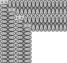
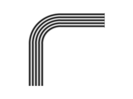
As detailed above, surface topography is used to direct the block copolymer pattern to create ordered alignment. In the simplest form of graphoepitaxy, conventional lithographic techniques are used to create trenches in a silicon wafer. The trenches are filled with block copolymer which orders into lamellae parallel to the sidewall on annealing.Farrell2009 ; Farrell2010 ; Fitzgerald2009 ; Stuen2010 The lamellae are on a much finer scale than the trench. Finally a selected monomer is chemically etched away and the remaining polymer used as an etch mask to facilitate pattern transfer to the substrate, creating nanowires on a scale too fine to be manufactured by conventional lithographic techniques.Morris2012 ; Borah2011 The failure of the pattern and hence the nanowires to persist around corners can be attributed to geometric frustration.ESGI62 The ordering pattern required to maintain continuity around a corner is inconsistent with the condition that the order parameter must be locally conserved, as illustrated in Figure 1.
In this work, we use simulations to investigate whether this problem can be overcome by using rounded corners. Simulations on the unit disk show that ordering patterns of concentric circles form.Ren2002 Thus the key remaining question is whether ordering patterns in the rounded corners are compatible with patterns in the straight trenches. We compare the topology (number of lamellae) of the microstructure in straight and annular geometries and show that once the inner radius exceeds a critical value the microstructures have the same topology suggesting that, in a rounded corner geometry, nanowires will persist around corners.
II Methods
To simulate the block copolymer ordering we use the extended Cahn-Hilliard equationChoksi2003 ; Wu2006 , which can be written in dimensionless form as
| (1) |
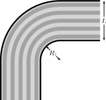
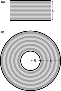
The geometry we are interested in is illustrated in Figure 2. However we carry out simulations in two separate geometries, illustrated in Figure 3. These are a straight region and an annular ring. These geometries allow one dimensional simulations to be carried out, making it possible to efficiently survey large regions of parameter space. We argue that, if solutions of the same topology exist in both the straight region and the annular ring, this provides strong evidence that lamellae will persist around rounded corners with the same parameters. We choose to simulate the case in which there are five lamellae in the straight trench, a situation realised experimentally, for example, in Ref. Farrell2010, , for a trench wide.
Thus the equations we are solving are
| (2) |
with boundary conditions
| (3) |
at and in the straight geometry and
| (4) |
with boundary conditions
| (5) |
at and in the annular geometry.
Numerical simulations were carried out using the finite difference method on a grid of 400 points. Timesteps of 0.1 dimensionless units were carried out using the implicit Euler method. We took following Ref. Wu2006, . We start the straight simulations with a small amplitude cosine wave with 4.5, 5 and 5.5 wavelengths in the domain. We determined the largest values at which these solutions are stable by the bisection methodNR . This allows us to determine the values of in which the longest wavelength solution to the extended Cahn-Hilliard equation has five lamellae (in a straight geometry).
We then sample and space. Again we start simulations with a small amplitude cosine wave, with five wavelengths in the domain, and the region of interest is one in which the final solution also has five wavelengths, i.e. five lamellae. As before we use bisection to find the limits of stability of this solution. This allows us to construct a ‘phase diagram’ showing regions in which solutions to the Cahn-Hilliard equation have the same topology in straight and annular geometries.
As a final check we carried out a two dimensional finite element simulation on a rounded corner geometry using the COMSOL software. The simulation geometry has and .
III Results
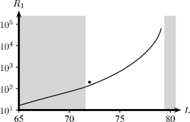
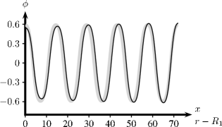
The one dimensional simulation results are summarised in Figure 4. They show that solutions with five lamellae are the longest wavelength stable solutions in straight geometries with . Solutions with the same topology occur in annular geometries for long enough wavelengths as shown in the ‘phase diagram’ in Figure 4. Five wavelength solutions to the extended Cahn-Hilliard equation in straight and annular geometries are shown in Figure 5. The solutions are reasonably similar, with the largest discrepancy occurring close to the origin, where the curvature is largest. The results of the two dimensional simulation is shown in Figure 6 and confirms that lamellae can persist round corners.
IV Discussion
The coexistence of solutions to the Cahn-Hilliard equations with the same topology in straight and annular geometries of the same width suggests that rounded corners could be a solution to the problem of templating or pattern transferring nanowires in complex geometries.
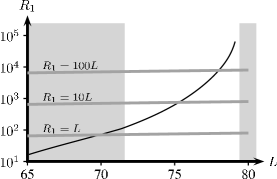
One important remaining question, addressed in Figure 7, is whether this coexistence occurs in a useful region of parameter space. If the values of at which coexistence occur are too large it will make the technique impractical, since the rounded corners will occupy too much space on the die. The figure shows that the ideal case of coexistence for does not occur. However, there is a region of phase space for which coexistence occurs for . This still seems small enough to make the technique potentially practical. A still larger region of parameter space is available if is allowed, but this may be too large to make the technique usable. Taking the trench width as (from Ref. Farrell2010, ), then and . At least the first of these seems small enough to be useful in devices. The situation modelled in Figure 5 would correspond to suggesting that sub-micron values of may be practical. As Figure 7 shows, to minimise , the should be made small as possible given the desired number of lamellae.
V Conclusions
The ordering of block copolymers into lamellar microstructures offers an attractive route to pattern transfer or template nanowires on a scale too small to be created by conventional lithographic techniques. One problem with this approach is the difficulty in maintaining continuity of the nanowire templates in complex geometries, such as corners. We have used simulations to investigate the feasibility of using rounded corners to overcome this problem. Our results suggest that this approach will work if the inner radius of curvature of the rounded corner is large enough. Rough estimates suggest that for a straight trench about wide containing five lamellae lamellae will persist around a rounded corner with a radius less than .
Acknowledgements.
WTL, ND and MV acknowledge support of the Mathematics Applications Consortium for Science and Industry (http://www.macsi.ul.ie) funded by the Science Foundation Ireland Mathematics Initiative Grant 06/MI/005. This work is part supported by the EU project LAMAND (contract Nr. 245565). The contents of this work are the sole responsibility of the authors. The support of the CRANN SFI CSET project is also acknowledged.References
- (1) M. C. Orilall and U. Wiesner, Chemical Society Reviews 40, 520 (2011).
- (2) C. F. van Nostrum, Soft Matter 7, 3246 (2011).
- (3) R. A. Farrell, T. G. Fitzgerald, D. Borah, J. D. Holmes, and M. A. Morris, International Journal of Molecular Sciences 10, 3671 (2009).
- (4) R. A. Farrell, N. Petkov, M. A. Morris, and J. D. Holmes, Journal of Colloid and Interface Science 349, 449 (2010).
- (5) T. G. Fitzgerald, R. A. Farrell, N. Petkov, C. T. Bolger, M. T. Shaw, J. P. F. Charpin, J. P. Gleeson, J. D. Holmes, and M. A. Morris, Langmuir 25, 13551 (2009).
- (6) K. O. Stuen, F. A. Detcheverry, G. S. W. Craig, C. S. Thomas, R. A. Farrell, M. A. Morris, J. J. de Pablo, and P. F. Nealey, Nanotechnology 21, 495301 (2010).
- (7) J. P. F. Charpin, V. Cregan, J. P. Gleeson, M. Hayes, W. T. Lee, S. B. G. O’Brien, and M. Vynnycky, “Spin-coating on nanoscale topography and phase separation of diblock copolymers,” Tech. Rep. (Smith Institute, 2008).
- (8) M. A. Morris et al., Nanoscale. In press.
- (9) D. Borah, M. T. Shaw, S. Rasappa, R. A. Farrell, C. O’Mahony, C. M. Faulkner, M. Bosea, P. Gleeson, J. D. Holmes, and M. A. Morris, Journal of Physics D: Applied Physics 44, 174012 (2011).
- (10) X. Ren and J. Wei, European Journal of Applied Mathematics 13, 479 (2002).
- (11) R. Choksi and X. Ren, Journal of Statistical Physics 113, 151 (2003).
- (12) X.-F. Wu and Y. A. Dzenis, Journal of Chemical Physics 125, 174707 (2006).
- (13) W. H. Press, S. A. Teukolsky, W. T. Vetterling, and B. P. Flannery, Numerical Recipes 3rd Edition: The Art of Scientific Computing, 3rd ed. (Cambridge University Press, New York, NY, USA, 2007).