Influence of a magnetic guide field on wakefield acceleration
Abstract
Enhancement of the trapping and optimization of the beam quality are two key issues of Laser Wake Field Acceleration (LWFA). The influence of stochastic acceleration on the trapping of electrons is compared to the one of cold injection. It is shown that when considering a high intensity wave perturbed by a low intensity counter-propagating wave, in the non-linear blowout regime, the influence of the colliding pulses polarizations (either parallel linear or positive circular) on the beam quality seems weak when the electron density is below critical density. The effect of a homogenous constant magnetic field , parallel to the direction of propagation of the pump pulse, is studied in the blowout regime. Transverse currents are generated at the rim of the bubble, which results in the amplification of the field at the rear of the bubble. Without field the beam periodically explodes and re-confines, this phenomenon is suppressed when reaches some threshold, which is a function of the laser pulses parameters (intensity, waist, duration). Therefore the dynamics of the beam is modified, its maximum energy is slightly boosted and above all transverse emittance reduced. Moreover the low energy tail, observed in the non magnetized case, can be completely suppressed leading to very sharp mono-energetic beam when is applied. If the available field is limited then one has to fine-tune the spatio-temporal shape and intensity of the colliding pulse in order to get an acute control on the beam quality.
pacs:
52.38.KdI Introduction
In laser-wakefield acceleration (LWFA) Tajima and Dawson (1979); Esarey et al. (1997); Faure et al. (2004); Mangles et al. (2004), a laser creates a plasma wave wakefield with a phase velocity close to the speed of light (). The acceleration gradients in these wakefields can easily exceed 100 GeV/m, hence a cm-long plasma based accelerator can produce GeV-energy electron beams. A particle injected in such a wave gains energy from the longitudinal component of the electric field, as long as the pump pulse is not depleted and the dephasing length is not reached. These wakefields have ideal properties for accelerating electrons. The transverse focusing field increases linearly with the radial distance and the accelerating longitudinal field is independent of the radial coordinate Rosenzweig et al. (1991); Lu et al. (2006a). LWFA can be split into three different options . The first corresponds to a plasma density , a pulse length () matching half of a plasma period and a spot size () roughly equals to the bubble radius, , where is the normalized vector potential of the laser. This is the idea of the bubble regime Pukhov and ter Vehn (2002); Gordienko and Pukhov (2005). For these conditions, a hundred-joule class laser would have an intensity of the order . In this regime, the electrons are continuously injected, this results in tremendous beam loading and the loaded wake is noisy. In this paper we explore different techniques to improve the beam quality of LWFA when electrons are injected in the wake with a colliding pulse. Hence, the bubble regime is not appropriate. We rather select moderate laser intensity and plasma density according to the guidelines proposed by Lu et al.Lu et al. (2007) to achieve a more controlled and stable blowout of the electrons. Self-injection of electrons can occur when the pump pulse intensity is high but the accelerating structure is almost the same. In this frame beam loading effects clamp further injection leading to beams with a smaller energy spread. In order to limit the computational requirements of our PIC simulations the propagation of the pump pulse will not exceed 1 cm. We tend to avoid self-injection into the wake by adjusting the pump pulse intensity and the electronic density. Many different combinations of polarizations can be chosen for both waves, each of these possibilities results in particular force acting on the plasma electrons, when the two waves collide Davoine et al. (2008). The first point of this article is to summarize the dependance to pump and colliding pulse intensities, and to plasma density of this force. The relative influence of stochastic heating and beat wave force on the injection mechanism, and later on the beam quality will be discussed. After the choice of polarization in the blowout regime is clarified, we focus on the study of wakefield acceleration in the presence of an external, homogenous, magnetic field and study its influence through simulations. The mechanisms leading to the enhancement of the beam quality will be examined. In a third part, fine-tuning of the counter-propagating low intensity pulse will be considered in order to limit the intensity of the external field. This situation will be illustrated in the case when the intensity of the pump pulse is raised to . Then we will conclude.
II Sensitivity of beam injection to wave intensity, plasma density and polarisation of lasers
II.1 Basic principles
The wakefield propagates in the plasma at the group velocity of the laser defined by : , where is the speed of light, and respectively denote the plasma and laser frequencies. We use the quasi-static approximation and assume that the potential created by the pump pulse only depends on , where and denote the space and time coordinates normalized by and respectively. Then, the hamiltonian of an electron in the wakefield potential , created by the pump pulse, reads :
| (1) |
where . The normalized transverse momentum is defined by , where is the transverse momentum and denotes the electron mass. The hamiltonian of a particle is an invariant , using (1) we deduce two solutions for the longitudinal momentum :
| (2) |
where . The separatrix between trapped and untrapped orbits is given by a critical value, , of the Hamiltonian. Replacing by in (2) and retaining we get the two branches of .
Let us now comment the dynamics of an electron in vacuum, in the presence of two counter-propagating laser pulses. The hamiltonian reads , the longitudinal force acting on the electron is given by
| (3) |
Taking only into account the influence of the lasers, denoted by their potential vectors and , we have . We will consider parallel linear polarization (P linear polarization) and positive circular polarization, that is and respectively. Substituting the above expressions in Eq. (3) yields
| (4) |
for the P linear polarization case, and
| (5) |
for the positive circular polarization case. When P linear or positive circular polarizations are used Eqs. (II.1) and (5) show the existence of a force spatially oscillating with a period. This force is not time-dependant, it is usually interpreted as a ponderomotive force associated with the beat-wave Fubiani et al. (2004); Kotaki et al. (2004); Faure et al. (2006); Davoine et al. (2008). We should compare the beatwave force to the longitudinal ponderomotive force, this latter scales as where is the pulse duration. Taking the maximum value of the ratio becomes
| (6) |
When electrons are trapped inside the -long beatwave buckets and cannot be wiped out by the longitudinal ponderomotive force. On the whole for both polarizations electrons will undergo the beatwave force, therefore when the separatrix is such that electrons will be trapped in the wakefield as a bunch Davoine et al. (2009). However in the P linear polarization case other terms are added to the force and the equations of the motion are no longer integrable, electron trajectories become chaotic Bourdier et al. (2005). This phenomenon known as stochastic heating can provide very large momenta to some electrons Sheng et al. (2002, 2004); Patin et al. (2005, 2006); Bourdier et al. (2007); Bourdier and Drouin (2009); Bourdier et al. (2010). When the beatwave force is not efficient and electrons can hardly be trapped with positive circular polarizations. In this case P linearly polarized colliding waves are necessary to give electrons the appropriate momentum in order to fill the gap between trapped and untrapped orbits. In the following two subsections, the sensibility of the injection process to polarization and intensity of the waves will be summarized.
II.2 Low density: Strong dependance to polarization and wave intensity
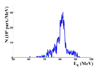
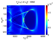
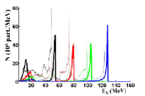
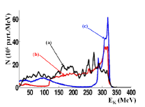
When the plasma density is about a weak variation of the pump pulse is sufficient to modify the mechanisms allowing trapping of a bucket in the wakefield. To illustrate this strong dependance to laser parameters we launched three sets of simulations with the PIC code CALDER Lefebvre et al. (2003). The simulation setup consists in two 30 fs linearly polarized waves with wavelength m having their electric fields either linearly or circularly polarized (orthogonal linear polarization is denoted by S). The pump pulse, which creates the accelerating wakefield, is focused to an m full width at half maximum (fwhm). The peak normalized vector potential of the main pulse is associated to the laser intensity by the formula , we considered and . The low intensity pulse is counter-propagating and is focused to a m focal spot at a peak normalized vector potential or . The waves interact with a mm-size plasma with a density . The fluctuations between the two regimes are illustrated by Figs. 1. When and the separatrix between trapped and opened orbits is higher than , in this case the beatwave force cannot provide enough momentum to electrons to push them in the wakefield. Nevertheless stochastic heating due to P linear polarizations is a way to bridge the gap and inject a bunch in the wakefield (Fig. 1(a)). When the separatrix is lowered (), in this case the beatwave force is enough to trap electrons in the wake therefore we can accelerate a beam using either P linear or positive circular polarizations. Note that no trapping occurs with negative circular polarizations, which is consistent with the theory introduced in subsection II.1. Indeed straightforward algebra gives , then the ponderomotive force hinders trapping of electrons. The quality of the accelerated beam will depend on the force which dominates during collision of the pulses. A relatively high intensity of the counter propagating laser () will foster stochastic heating Bourdier and Drouin (2009); Bourdier et al. (2010) and a higher charge will be injected with P linear polarizations compared to positive circular polarizations (Fig. 1(b)). On the contrary, if we reduce the intensity of the counter propagating pulse () the beatwave force is favored and rules the injection mechanism (Fig. 1(c)). In this latter case, the beam quality is better without stochastic heating.
II.3 Very low density: Weak dependance to laser polarization
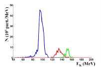
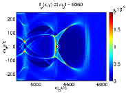
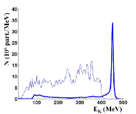
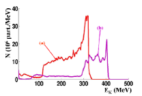
We now chose parameters relevant for the study of the blowout regime Malka et al. (2008); Martins et al. (2010); Lu et al. (2006a, b). The plasma density was set to and the pump pulse intensity to , the rest of the simulation setup was not modified. Considering two circularly polarized waves rotating in the same direction (positive circular polarizations) is as efficient as considering P linear polarizations (Fig. 2). It means that in this case cold injection Davoine et al. (2009, 2010) due to the beating force is the key mechanism governing electron injection. Stochastic acceleration weakly changes the number and the energy of electrons trapped in the wake field. The electron momentum distribution along the direction of propagation of the waves during their collision shows that the effects on electron dynamics of the two polarizations are close, as a result the electron energy distributions are almost identical (Fig. 2).
This dominant influence of the beating force upon injection was not clearly stated by Davoine et al. Davoine et al. (2009), here we underline that no relevant difference is triggered through use of P linear polarizations or positive circular polarizations in the blowout regime. The next section is devoted to the study of a new means to enhance beam quality after colliding pulse injection, in the blowout regime.
III Influence of a magnetic guide field
The influence of a constant homogeneous guide magnetic field on LWFA is studied in this part. This magnetic field is assumed to be parallel to the direction of propagation of the waves. Electrons are still externally injected using a colliding counter propagating laser pulse Faure et al. (2006). The idea is to guide the electrons in order to improve the quality of the beam which is trapped in the wake field. This mechanism was first proposed in the context of LWFA, with a single pump laser () and an electronic density prone to self-injection into the wake field Hur et al. (2008), with these parameters self-injection can be dramatically enhanced and beam quality degraded. Here we aim at studying the influence of a magnetic guide field in the blowout regime Lu et al. (2007) with colliding pulse injection of the electrons, hence we chose and , thus abiding by and criteria proposed by Martins et al. Martins et al. (2010). The required magnetic field necessary to curve electron trajectories is about a hundred teslas Hur et al. (2008), such values are particularly strong but still available from the current pulsed magnet technology Lagutin et al. (2003), the most advanced magnets can reach 90T for tens of ms durations and centimeter size lengths Zherlitsyn et al. (2010). The simulation setup consists in two 30 fs linearly polarized counterpropagating waves with m wavelength. They propagate along a constant homogeneous guide field in a cm-long plasma, the normalised value of is given by . Their electric fields are in the same plane (P linear polarizations). The pump pulse, which creates the accelerating wakefield, is focused to an m full width at half maximum. The peak normalized vector potential for this pulse is still . The low intensity pulse is focused to a m focal spot at a peak normalized vector potential . The plasma frequency in the presence of a magnetic field can be approximated by where and represent the frequencies of the magnetized and unmagnetized plasma, respectively. The cyclotron frequency is defined by . When T and T, one has and respectively which proves that the magnetization of the plasma may have some effect on the deformation of the wakefield as will be further discussed. Before the collision of the waves the magnetization has no influence on self-injection, no electron is trapped in the wake.
III.1 Electronic density and transverse currents induced at the rim of the bubble
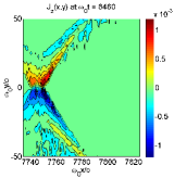
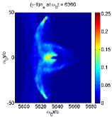
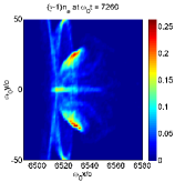
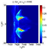
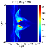
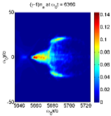
Let us first identify the differences brought by the addition of a magnetic guide field to the electronic distribution at the vicinity of the bubble boundaries (Figs. 3). After the electron beam injection into the wake field, the strong ponderomotive force due to the main pulse still repels electrons and thus provides them longitudinal and transverse momenta. In the absence of magnetic field, electrons are submitted to the recall electric field induced by the bubble but the balance between this force and the ponderomotive force is favorable to the latter ; as a result electrons flee along straight line trajectories (Fig. 3(a)).
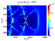
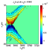
When a longitudinal magnetic field is added electrons start to revolve around the bubble as a result of the magnetic force, this force combined with the electric force induced by the bubble completely modifies the dynamics of the electrons. The gyro-radius of the electrons with is reduced when is raised. Therefore the corresponding flight path in the plane appear to be bent, the trajectory will be even more curved when the applied field is stronger (Figs. 3(b)-3(c)). When electrons revolve around the bubble they create a current perpendicularly to the plane of the figure, as evidenced by Figs. 4-4. Given the value of the electronic density at the rear of the bubble (), we deduce from Figs. 4 the time averaged speed of electrons revolving around the bottleneck of the bubble . This current will act as a small solenoid, and thus the longitudinal magnetic field will be amplified. This feature and its influence on the beam dynamics will be detailled in the next subsection.
III.2 A new mechanism to enhance the beam quality
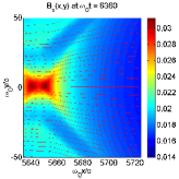
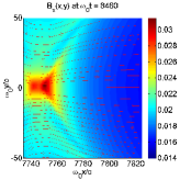
The intensity of the magnetic field is almost doubled locally (Figs. 5) compared to the initial () uniform map of . We shall underline that this pattern is stable as we obtain quasi identical maps of in this region of the bubble when the pump pulse has just entered the plasma around . Moreover we note that the geometry of the magnetic field lines is weakly altered by the electronic density modulations induced by the propagating bubble. Magnetic field lines stay almost parallel to the propagation direction.
Let us now examine the effect of the magnetic field on the dynamics of the accelerated beam. To evidence the differences between the magnetized and the unmagnetized regimes, we plotted kinetic energy density maps showing the evolution of the trapped beam at the rear of the bubble. In the unmagnetized case (Figs. 6), the beam alternatively explodes (due to space charge effects) and focalises (due to the focalizing effect of the transverse electric field). This behavior has a typical period. Note that the beam acceleration is degraded because the components of the splitted beam will not see the maximal value of the longitudinal electric field (which is located on axis). The dynamics is completely different in the magnetized case (Figs. 7), the longitudinal magnetic field is strong enough to curve the trajectories and hinder the explosion of the beam. As a result the beam is almost concentrated on axis, the transverse emittance is reduced and the main part of the beam, which also corresponds to the region where the magnetic field is the strongest, always sees the maximum value of the electric field. Next we will quantify the enhancement of the beam quality through the evolution of the energy distribution functions of the beam.
III.3 Enhancement of the beam quality
As already mentionned, in the magnetized case, the beam is submitted to a more uniform accelerating field, this pattern boosts the particle acceleration leading to a slightly higher maximum kinetic energy when compared to the unmagnetized case (Fig. 8).
| 7000 | 9000 | 11000 | 13000 | |
|---|---|---|---|---|
| (T) | ||||
| 0 | 5.33% | 5.88% | 4.53% | 6.61% |
| (2.05%) | (1.09%) | (0.81%) | (0.97%) | |
| 125 | 5.50% | 5.45% | 3.41% | 3.96% |
| (5.03%) | (4.89%) | (1.94%) | (1.58%) | |
| 250 | 3.96% | 2.67% | 2.84% | 2.91% |
| (3.72%) | (2.75%) | (1.54%) | (0.63%) |
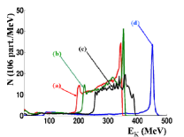
The focalizing magnetic field reduces the low energy tail of the energy spectrum, as can be seen in Figs 8. Obviously, this trend is enhanced when the guide field rises. With no guide field, the relative variation of the energy at full width at half maximum (fwhm) is excellent, but the rms value of the energy spread has small variations and reaches 7% at the end of the simulation (Table 1). When T, on the one hand the spread of the low energy tail of the distribution is reduced as shown by Fig. 8(a), and confirmed by the rms value , but on the other hand is slightly degraded. When T, untrapped electrons carrying energies about 10 Mev concentrate ( locally reaches ) at the rear of the bubble. These low energy (i.e. Mev) electrons are evidenced by bumps in the beam energy distribution (Fig 8(b)). This low energy bump slowly slides out of the simulation box as these electrons are not injected in the wakefield, and therefore should not be considered for the interpretation of the diagnostics concerning the accelerated beam. According to this comment, we note that a 250 T guide field is enough to completely suppress the low energy tail during the whole simulation. A clear enhancement of the beam quality is obtained, first the final rms value is below 3% and (table 1) thus providing a very sharp control on the final energy of the beam, and second the number of electrons at the highest energies does not vanish, as in the unmagnetized case, but on the contrary grows up to part/Mev, nearly twice the value of the unmagnetized case ! To our knowledge such an acute mono-energetic electron beam production, with complete extinction of the low energy tail has never been evidenced.
For a given pump pulse, two well-known controllers of the low intensity laser can be used to optimize the beam quality. The low intensity pulse duration can be monitored and the transverse fwhm of the spatial envelope adjusted, these two parameters together usually make it possible to get a quasi-mono-energetic electron beam in the blow-out regime Martins et al. (2010); Davoine et al. (2009). There are other ways to enhance the beam quality. For example, one can resort to a longitudinal gradient of the electronic density to enhance trapping Davoine et al. (2009); Geddes et al. (2004); Faure et al. (2010). In an alternate approach, assuming initially homogenous plasma, one can slowly evolve the laser pulse shape to alternate periods of expansion and contraction of the bubble, to respectively trigger and stop self-injection Kalmykov et al. (2011) of the electrons into the bubble. However this technique seems hard to adjust to get a unique mono-energetic bunch. In this paper, injected electrons are confined by using a magnetic guide field but we note that the intensity of the field, required to substantially enhance the beam quality, depends on lasers pulse shapes and durations. In this section we did not pay attention to the tuning of the low intensity colliding pulse, we have shown that the guiding induced by is enough beyond some threshold, function of the parameters of the simulation. However, if we decide to lower the blowout stability by increasing the main pulse intensity, the required intensity of the guide field grows to values largely out of reach of the current technology, then fine-tuning of the colliding pulse becomes necessary. The next section is devoted to this issue.
IV Influence of a magnetic guide field at higher intensities
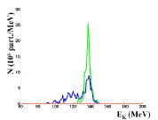
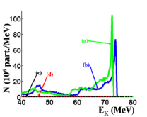
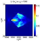
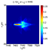
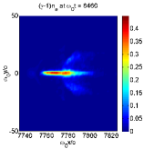
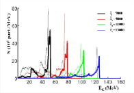
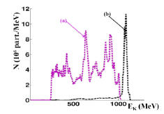
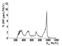
A very high intensity wave is considered now, the pump pulse which is linearly polarized is assumed to have a peak normalized intensity , and a duration of 30 fs. It is focused to a m large focal spot. The colliding pulse has a peak normalized intensity , a 30fs duration and three focal spot sizes were considered m, 36 m and 10 m. The wavelength of the waves is m. In these simulations, the plasma density is still . Unless otherwise mentionned the following simulations were run with T. When considering and a counter-propagating wave focused to a 10 m focal spot, one has a paramount effect of the magnetic field on the distribution function (Table 2, Fig. 9). The electron energy distribution becomes almost mono-energetic. After the laser pulse has propagated through the plasma by 3.8 mm, the electron energy distribution is still quite mono-kinetic and the maximum electronic energy exceeds one GeV (Fig. 9(b)). Table 2 shows the evolution of the energy spread of the electron energy distribution with time. When no field is applied the quality decreases whereas we get an acute control on the beam energy with . It must be pointed out that the accelerated charge is small (close to 50 picocoulombs). The electron energy distributions corresponding to four focal spots are compared at some time. Figure 13 shows that the distribution becomes much more mono-energetic when the focal spot of the perturbing wave is smaller than the one of the main pulse. The magnetic field is much more efficient when considering a small value of D. Then, we have checked that this peak exists in a very small range of values close to . When the distribution function shows a lower magnitude peak, and the charge accelerated in the first bubble is about 10 picocoulombs. The peak still exists when . But in the case of a higher value of (for instance ) the energy distribution does not show a very thin high-energy peak any longer because the injected charge is higher and the magnetic field is too weak to concentrate the beam efficiently.
| 7000 | 13000 | 22000 | 30000 | |
|---|---|---|---|---|
| (T) | ||||
| 0 | 40.5% | 41.2% | 36.0% | 33.2% |
| (23.0%) | (86.1%) | (59.3%) | (100.9%) | |
| 125 | 6.4% | 1.7% | 5.0% | 3.35% |
| (4.85%) | (1.3%) | (2.0%) | (2.6%) |
No high-energy peak was seen in the distribution function for larger values of , actually the same kind of distribution is obtained when , and . Figure 11 shows that the electron energy distribution becomes more mono-energetic when the magnitude of the magnetic guide field is increased to 250 T, accordingly with the results obtained with a lower intensity of the pump pulse () in section III.3. Figure 12 shows that, a shorter pulse duration ( fs) for the counterpropagating wave, also makes the electron energy distribution more mono-energetic. Then, in order to obtain a more mono-energetic distribution when and , a very strong magnetic field and a short duration for the counterpropagating wave fs were considered (Fig. 13). As expected, a high energy peak is obtained. One should point out that the charge accelerated in the first bubble is still close to 50 picocoulombs. To summarize when is too high, that is when the charge injected in the wakefield exceeds some treshold, we can not stop a drop of the beam quality by imposing an external field alone, at least the main parameters (focal spot size and duration) of the colliding pulse shall be reduced.
V Conclusions
In the first part of this paper, we summarized some essential results about the most efficient choice of polarizations for injection in the bubble, in the colliding pulse scheme. At rather high electron density () and moderately relativistic electromagnetic wave intensity (), more particles are accelerated to high energies in the case of P linear polarizations that is to say when electrons undergo the action of the beatwave force and all the others. For higher intensities and lower densities () the beatwave force, that is cold injection, can be more efficient. The second and main part of this paper has been devoted to the study of the influence of an external static magnetic field on the wakefield acceleration process, within the colliding pulse scheme. To our knowledge this idea was never explored. The magnetic field is supposed parallel to the direction of propagation of the two counter-propagating waves. It has been shown that the field creates a transverse current, the latter current can induce a raise of at the rear bottleneck of the bubble. Therefore the beam dynamics is substantially modified as the beam is constrained to stay in the maximum acceleration region of the bubble. Beam emittance is considerably reduced and maximum kinetic energy slightly boosted compared to the unmagnetized case. This mechanism provides means to dramatically enhance the beam quality in the blowout regime. We achieved tremendous amelioration with the setup: , and . After roughly 4 mm of wakefield acceleration, without field the electronic energy distribution is noisy whereas we get when the plasma is magnetized with a 125 T field. Nevertheless the intensity of the field may be limited by technological considerations Zherlitsyn et al. (2010), thus acute control of the beam quality may require some fine-tuning of the colliding pulse parameters. For a given pump pulse, one should adapt the intensity, duration and focal spot size of the counter-propagating laser pulse.
References
- Tajima and Dawson (1979) T. Tajima and J. Dawson, Phys. Rev. Lett. 43, 267 (1979).
- Esarey et al. (1997) E. Esarey, R. F. Hubbard, W. P. Leemans, A. Ting, and P. Sprangle, Phys. Rev. Lett. 79, 2682 (1997).
- Faure et al. (2004) J. Faure, Y. Glinec, A. Pukhov, S. Kiselev, S. Gordienko, E. Lefebvre, J.-P. Rousseau, and F. B. V. Malka, Nature 431, 541 (2004).
- Mangles et al. (2004) S. P. D. Mangles, C. D. Murphy, Z. Najmudin, A. G. R. Thomas, J. L. Collier, A. E. Dangor, E. J. Divall, P. S. Foster, J. G. Gallacher, C. J. Hooker, D. A. Jaroszynski, A. J. Langley, W. B. Mori, P. A. Norreys, F. S. Tsung, R. Viskup, and B. R. W. K. Krushelnick, Nature 431, 535 (2004).
- Rosenzweig et al. (1991) J. B. Rosenzweig, B. Breizman, T. Katsouleas, and J. J. Su, Phys. Rev. A 44, R6189 (1991).
- Lu et al. (2006a) W. Lu, C. Huang, M. Zhou, W. Mori, and T. Katsouleas, Phys. Rev. Lett. 96, 165002 (2006a).
- Pukhov and ter Vehn (2002) A. Pukhov and J. M. ter Vehn, Appl. Phys. B 74, 355 (2002).
- Gordienko and Pukhov (2005) S. Gordienko and A. Pukhov, Phys. Plasmas 12, 043109 (2005).
- Lu et al. (2007) W. Lu, M. Tzoufras, C. Joshi, F. S. Tsung, W. B. Mori, and J. V. and R. A. Fonseca and L. O. Silva, Phys. Rev. ST Accel. Beams 10, 061301 (2007).
- Davoine et al. (2008) X. Davoine, E. Lefebvre, J. Faure, C. Rechatin, A. Lifschitz, and V. Malka, Phys. Plasmas 15, 113102 (2008).
- Fubiani et al. (2004) G. Fubiani, E. Esarey, C. Schroeder, and W. Leemans, Phys. Rev. E 70, 016402 (2004).
- Kotaki et al. (2004) H. Kotaki, S. Masuda, M. Kando, and J. Koga, Phys. Plasmas 11, 3296 (2004).
- Faure et al. (2006) J. Faure, C. Rechatin, A. Norlin, A. Lifschitz, Y. Glinec, and V. Malka, Nature letters 444, 737 (2006).
- Davoine et al. (2009) X. Davoine, E. Lefebvre, C. Rechatin, J. Faure, and V. Malka, Phys. Rev. Lett. 102, 065001 (2009).
- Bourdier et al. (2005) A. Bourdier, D. Patin, and E. Lefebvre, Physica D 206, 1 (2005).
- Sheng et al. (2002) Z.-M. Sheng, K. Mima, Y. Sentoku, M. Jovanovic, T. Taguchi, J. Zhang, and J. Meyer-Ter-Vehn, Phys. Rev. Lett. 88, 055004 (2002).
- Sheng et al. (2004) Z.-M. Sheng, K. Mima, J. Zhang, and J. Meyer-Ter-Vehn, Phys. Rev. E 69, 016407 (2004).
- Patin et al. (2005) D. Patin, A. Bourdier, and E. Lefebvre, Laser and Particle Beams 23, 297 (2005).
- Patin et al. (2006) D. Patin, E. Lefebvre, A. Bourdier, and E. D’Humi res, Laser and Particle Beams 24, 223 (2006).
- Bourdier et al. (2007) A. Bourdier, D. Patin, and E. Lefebvre, Laser and Particle Beams 25, 169 (2007).
- Bourdier and Drouin (2009) A. Bourdier and M. Drouin, Laser and Particle Beams 27, 545 (2009).
- Bourdier et al. (2010) A. Bourdier, M. Drouin, and X. Davoine, IEEE transactions on plasma science 38, 728 (2010).
- Lefebvre et al. (2003) E. Lefebvre, N. Cochet, S. Fritzler, V. Malka, M.-M. Al onard, J.-F. Chemin, S. Darbon, L. Disdier, J. Faure, A. Fedotoff, O. Landoas, G. Malka, V. M ot, P. Morel, M. R. L. Gloahec, A. Rouyer, C. Rubbelynck, V. Tikhonchuk, R. Wrobel., P. Audebert, and C. Rousseaux, Nucl. Fusion 43, 629 (2003).
- Malka et al. (2008) V. Malka, J. Faure, Y. Gauduel, E. Lefebvre, A. Rousse, and K. Phuoc, Nature Physics 4, 447 (2008).
- Martins et al. (2010) S. Martins, R. Fonseca, W. Lu, W. Mori, and L. Silva, Nature Physics 6, 311 (2010).
- Lu et al. (2006b) W. Lu, C. Huang, M. Zhou, M. Tzoufras, F. Tsung, W. Mori, and T. Katsouleas, Phys. Plasmas 13, 056709 (2006b).
- Davoine et al. (2010) X. Davoine, A. Beck, A. Lifschitz, V. Malka, and E. Lefebvre, New J. Phys. 12, 095010 (2010).
- Hur et al. (2008) M. Hur, D. Gupta, and H. Suk, Phys. lett. A 372, 2684 (2008).
- Lagutin et al. (2003) A. Lagutin, K. Rosseel, F. Herlach, J. Vanacken, and Y. Bruynseraede, Meas. Sci. Technol. 14, 2144 (2003).
- Zherlitsyn et al. (2010) S. Zherlitsyn, T. H. and B. Wustmann, and J. Wosnitza, IEEE transactions on applied superconductivity 20, 672 (2010).
- Geddes et al. (2004) C. G. R. Geddes, C. Toth, J. van Tilborg, E. Esarey, C. B. Schroeder, D. Bruhwiler, C. Nieter, and J. C. W. P. Leemans, Nature 431, 538 (2004).
- Faure et al. (2010) J. Faure, C. Rechatin, O. Lundh, L. Ammoura, and V. Malka, Phys. Plasmas 17, 083107 (2010).
- Kalmykov et al. (2011) S. Y. Kalmykov, A. Beck, S. A. Yi, V. N. Khudik, M. C. Downer, E. Lefebvre, B. Shadwick, and D. P. Umstadter, Phys. Plasmas 18, 056704 (2011).