Radiation from elementary sources in a uniaxial wire medium
Abstract
We investigate the radiation properties of two types of elementary sources embedded in a uniaxial wire medium: a short dipole parallel to the wires and a lumped voltage source connected across a gap in a generic metallic wire. It is demonstrated that the radiation pattern of these elementary sources have quite anomalous and unusual properties. Specifically, the radiation pattern of a short vertical dipole resembles that of an isotropic radiator close to the effective plasma frequency of the wire medium, whereas the radiation from the lumped voltage generator is characterized by an infinite directivity and a non-diffractive far-field distribution.
pacs:
42.70.Qs, 78.20.Ci, 41.20.JbI Introduction
Wire media, generically defined as structured materials formed by arrays of long metallic wires, Brown (1953); Rotman (1962); Pendry et al. (1996) is perhaps the class of metamaterials whose effective response is better understood. Particularly, during the last decade a vast body of theoretical methods and analytical tools have been developed which enable characterizing the effective electromagnetic response of wire-based materials in different scenarios with great accuracy. Maslovski et al. (2002); Pokrovsky and Efros (2002); Belov et al. (2003); Silveirinha and Fernandes (2005); Simovski and Belov (2004); Nefedov et al. (2005a, b); Silveirinha (2006a, b, 2009a); Silveirinha and Fernandes (2008); Luukkonen et al. (2009); Yakovlev et al. (2009); Maslovski and Silveirinha (2009); Nefedov (2010) However, a bit surprisingly, the problem of radiation by localized external sources embedded within wire media, has only been cursorily discussed in the literature.Ikonen et al. (2006); Lovat et al. (2006); Burghignoli et al. (2008a, b)
This gap can be explained in part because of the peculiar electromagnetic response of wire media, which are typically characterized by strong spatial dispersion in the long wavelength limit,Belov et al. (2003) and this property greatly complicates the analytical modeling. In simple terms, a medium is spatially dispersive if the polarization vector at some generic point in space depends not only on the macroscopic electric field, but also on the gradient of the field, and possibly higher order derivatives.Agranovich and Ginzburg (1966)
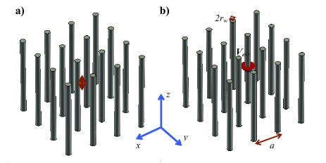
The objective of this work is to characterize the radiation properties of elementary external localized sources placed within a wire medium using an effective medium approach. Specifically, we are interested in the following two scenarios: (i) a short vertical dipole is embedded in the wire medium (Fig. 1a) and (ii) an external lumped voltage source is connected across a gap in a generic metallic wire (Fig. 1b). As will be detailed in Section II, these sources are modeled in terms of the Dirac delta function (Dirac-). It is, however, important to make clear at the outset that an effective medium description of the radiation problem is only possible if the source is localized on a larger scale than the characteristic dimension of the metamaterial (e.g., the lattice constant , see Fig. 1). Hence, the short vertical dipole considered here should be understood as some external current spread over a region of space whose characteristic diameter in the -plane is larger or equal than , but much smaller than the wavelength. Similarly, even though for the purpose of illustration and discussion we say that in case (ii) the voltage source is connected across the gap of a single wire, it is more accurate to imagine such source as an array of voltage generators, distributed over a region of space whose characteristic diameter is larger than , being each voltage generator connected across a gap in a metallic wire lying within the mentioned region. With the exception of the immediate vicinity of these sources, the solution determined with our theory (based on the Dirac- distribution) should describe accurately the radiated fields.
One of the challenges in the characterization of the radiation by a localized source within a wire medium is related to the calculation of quantities such as the Poynting vector or the radiation intensity (i.e. the power radiated per unit of solid angle). Indeed, in general the usual form of the Poynting vector, , does not hold in case of spatially dispersive materials.Agranovich and Ginzburg (1966); Costa et al. (2011) Moreover, there is no known theory to determine the Poynting vector in a general spatially dispersive material, and the only case that is actually understood and for which closed analytical formulas are available, is when the electromagnetic fields have a plane wave type-spatial variation. Agranovich and Ginzburg (1966) In this work, we derive closed analytical formulas that enable calculating explicitly the Poynting vector and the electromagnetic energy density in uniaxial wire media for arbitrary electromagnetic field distributions. This is one of the key results of the paper.
To do this, we rely on the theory of our earlier works, Maslovski and Silveirinha (2009); Maslovski et al. (2010) where we have shown that the effective medium response of the wire medium can be modeled using a quasi-static model, based on the introduction of two additional variables and . What is remarkable about such a model, is that the relations between the macroscopic electromagnetic fields and the additional variables and are in space. Therefore, such formalism enables describing the unconventional electrodynamics of the wire medium using a local approach, without requiring the definition of an effective spatially dispersive dielectric function, which would lead to nonlocal relations between the polarization vector and the macroscopic electric field.Belov et al. (2003) It is important to mention that the introduction of the additional variables is not just a trick that simplifies the modeling of the wire medium: it is actually full of physical significance, and elucidates about the internal physical processes that determine the macroscopic response of the metamaterial. Indeed, the variable can be understood as the electric current that flows along the metallic wires (interpolated in such a manner that it becomes a continuous function defined in all space), whereas the variable can be understood as the average potential drop from a given wire to the boundary of the respective unit cell (the potential is interpolated in the same manner as the current). For more details, the reader is referred to Refs. Maslovski and Silveirinha, 2009; Maslovski et al., 2010.
This paper is organized as follows. In Section II, we briefly review the quasi-static model of the wire medium, and formulate the radiation problem for the two excitations of interest. In Section III we solve the pertinent radiation problem in the spectral domain. First, we discuss the general case of a stratified (along ) structure, and after this we analyze in details the particular case of an unbounded uniform structure. In Section IV, we show that for an unbounded uniform structure the fields radiated by the elementary external sources can be as well directly determined from the nonlocal dielectric function of the metamaterial. After this, in Section V we derive a general Poynting theorem that expresses the conservation of energy in wire media, and in Section VI we use these results to obtain the asymptotic form of the Poynting vector in the far-field, as well as the directive gain, directivity, and the power radiated by a short vertical dipole. The conclusions are drawn in Section VII. In this work, we assume that in case of time harmonic regime the time variation is of the form .
II Local formulation based on the introduction of additional variables
In Refs. Maslovski and Silveirinha, 2009; Maslovski et al., 2010 it was shown that the internal physical processes that determine the macroscopic response of a wide class of wire media, are intrinsically related to the dynamics of the electric current along the wires and the additional potential , whose physical meaning was already discussed in Introduction. In particular, it was proven that for the case of straight wires oriented along the -direction the macroscopic electromagnetic fields satisfy
| (1) | ||||
| (2) |
where is the permittivity of the host material, is the area of the unit cell, and is the period of the wire medium (Fig. 1). Notice that unlike in our previous works,Maslovski and Silveirinha (2009); Maslovski et al. (2010) here we admit the possibility of an external distributed current source . The electromagnetic fields are coupled to the current and additional potential via a set of transmission line-type equations:
| (3) | ||||
| (4) |
In the above, , , and represent the capacitance, inductance, and self-impedance of a wire per unit of length, respectively, and explicit formulas for those parameters can be found in our previous papers. The real part of is related to the ohmic loss in the metallic wires, whereas its imaginary part is related to the kinetic inductance of the electrons in the metal. As compared to Refs. Maslovski and Silveirinha, 2009; Maslovski et al., 2010 now we allow for an external lumped voltage source (with amplitude ) to be placed across a gap in the wire in the central unit cell. It is simple to check based on the theory of Ref. Maslovski and Silveirinha, 2009, that this lumped voltage source is modeled by the term . Notice that similar to the current and additional potential, the lumped generator is interpolated so that it becomes a function defined over all space.
In the next section, we will determine the solution of the radiation problems sketched in Fig. 1, based on the system of Eqs. (1)–(4). It should be emphasized that such a system of equations is local in the sense that all the relevant medium parameters (, , , , and ) are independent of the gradient and higher order derivatives of the electromagnetic fields, , and . This contrasts with the usual formulation based on the effective dielectric function, which does not require the introduction of additional variables but in which the dielectric function depends explicitly on the wave vector.Belov et al. (2003); Silveirinha (2006b) This will be further discussed in Section IV.
For future reference, we note that from Eqs. (3)–(4) it follows that
| (5) |
In the above, it was supposed that , , and may depend on (but not on and ), which can happen in case of a stratified wire medium (with direction of stratification along ), such that either the permittivity of the host medium or the radii of the wires varies with .
III The radiation problem
Next, we derive the solution of the radiation problem in terms of two scalar potentials. We admit that the external current density describes a short vertical dipole, so that that , where represents the electric dipole moment. Since the Maxwell equations are linear it is possible to solve the two radiation problems sketched in Fig. 1 simultaneously. This will be done in what follows.
III.1 Solution in terms of two scalar potentials for the general case of a stratified structure
For generality, in this subsection, we admit that , , , and may depend on , which as discussed previously, may be useful to study problems of radiation in stratified media. We look for a solution of (1)–(4) such that the macroscopic electromagnetic fields are written in terms of a Hertzian potential so that
| (6) | |||||
| (7) |
It can be easily verified that (6)–(7) satisfy, indeed, the Maxwell equations (1)–(2), provided that
| (8) |
where . Hence, substituting (7) into (5) and using the above result, it follows that
| (9) |
where we defined the effective dipole moment for the combined excitations:
| (10) |
Notice that depends on both and , because we allow for the simultaneous excitation of the wire medium with the two pertinent types of elementary sources.
For convenience, let us introduce the auxiliary potential
| (11) |
where is the so-called plasma wave number of the wire medium,Maslovski and Silveirinha (2009); Belov et al. (2003); Silveirinha (2006b) which may be calculated using, for example, the approximate formula applicable to both square and hexagonal wire lattices , where is the radius of the metallic wires. Using the fact that for straight unloaded wires , it follows that Eqs. (8) and (9) are equivalent to
| (12) | |||
| (13) |
where we put and . Hence, to determine the solution of our problem, we need to solve this coupled system of partial differential equations with unknowns and .
To do this, it is most convenient to work in the Fourier domain. Defining and as the Fourier transform of and in the plane, respectively, so that
| (14) |
and is defined similarly, it follows that
| (15) | |||
| (16) |
where . Thus, we have reduced the radiation problem to the solution of a system of linear ordinary differential equations.
III.2 The case of a homogeneous medium
From hereafter, we restrict our attention to the particular case of a homogeneous and uniform medium, for which the structural parameters , , , and can be assumed independent of . In such a case, the system (15)–(16) can be rewritten in a compact matrix notation as follows:
| (23) | ||||
| (26) |
The general solution of the homogeneous problem, when , can be easily found using standard methods, and is given by
| (31) | ||||
| (34) |
where , with are integration constants, and and are the propagation constants along the direction of the so-called quasi-transverse electromagnetic () and transverse magnetic () modes supported by the bulk wire medium. These parameters are defined consistently with Refs. Silveirinha, 2006b; Silveirinha et al., 2007, and satisfy
| (35) | ||||
| (36) |
In case of perfectly conducting wires, we have , and thus . In such a case the propagation constants of the and modes reduce to the well known forms, and , respectively.Belov et al. (2003)
Since the solution of (26) is obviously an even function of , we may try a solution of the form
| (41) | ||||
| (44) |
By direct substitution into (26), it is readily found that the unknown constants and are required to satisfy
| (49) | ||||
| (52) |
This yields
| (53) | ||||
| (54) |
Substituting this result into Eq. (44), we finally obtain the desired solution
| (55) |
The inverse Fourier transform of is given by
| (56) |
where is the zero-order Bessel function of the first kind, , and in the second identity we used the fact that is a function of . In general, this Sommerfeld-type integral can only be evaluated using numerical methods. Obviously, it is possible to write a similar formula for .
III.3 Perfectly electric conducting wires
Let us now study what happens when to a first approximation the metal can be modeled as a perfect electric conductor (PEC), so that . In such a situation, Eq. (55) simplifies to
| (61) | ||||
| (64) |
We will discuss separately the two scenarios of interest. Let us consider first that , so that the metamaterial is excited solely with the short vertical dipole. In this case, , and thus we obtain simply
| (65) |
The corresponding inverse Fourier transforms can be evaluated analytically in a trivial manner. This yields
| (66) |
with and .
Hence, it is immediately seen that the mode (which in the case of a lossless metal is exactly transverse electromagnetic mode () with respect to the -direction Belov et al. (2003)) does not contribute to the radiation field of the short vertical dipole. This may look surprising at first, but it is actually simple to understand. Indeed, it is well known that the electric Green dyadic in a periodic structure (e.g. a photonic crystal or a metamaterial) can be written as a weighted summation of terms such as where stands for a generic natural mode of the system, and represents the tensor product.Sakoda (2001) In particular, this immediately implies that a TEM mode (with respect to the -direction) cannot possibly contribute to the field radiated by a short vertical dipole, because its contribution would be proportional to , whereas for a TEM mode . Notice that this discussion applies actually to the microscopic electromagnetic fields (before homogenization on the scale of the lattice constant), but it clearly indicates that the TEM mode cannot contribute as well to the radiated field in the framework of a macroscopic theory, consistent with Eq. (66). It is interesting to note that in the presence of loss the contribution of the mode to the radiation field does not vanish [the first addend of Eq. (55) does not vanish when ], which is fully consistent with the microscopic theory, because in case of loss the electric field associated with the mode has a small longitudinal component (i.e. a component along the direction).
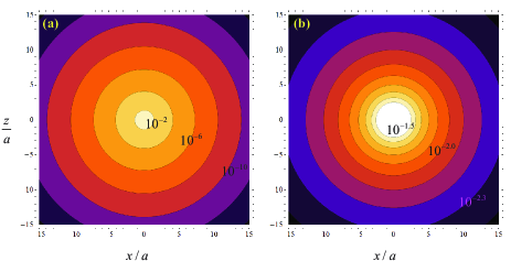
The result (66) implies two unexpected things. First, despite the anisotropy of the wire medium, the wavefronts are spherical surfaces! Second, the emission of radiation is possible only above the effective plasma frequency of the metamaterial, . The latter property is actually a direct implication of the TEM mode not being excited, as discussed above. To illustrate variation in space of the potential , we plot in Fig. 2 the contour plots of for two different frequencies of operation. The wire medium is formed by PEC wires with standing in a vacuum. The plasma wave number of the effective medium is . Thus, the example of Fig. 2a corresponds to a frequency below , whereas the example of Fig. 2b corresponds to a frequency above . This explains that in the former case the potential is strongly localized in the vicinity of the dipole, whereas in the latter case the potential decays much more slowly as .
At first glance, the result (66) could suggest that the electric field radiation pattern should be similar to that of a Hertzian dipole standing in a homogeneous isotropic plasma with a Drude dispersion. As it will be shown in Section VI, this is not true.
Next, we consider the case , so that the wire medium is excited by a lumped voltage source (Fig. 1b). In this scenario, the contribution of the TEM mode to the radiation field does not vanish. Indeed, the inverse Fourier transform of the first term in the right-hand side of (64) can be readily calculated and is equal to
| (67) |
where is the modified Bessel function of the second kind. On the other hand, the auxiliary potential (11) associated with the wire current satisfies .
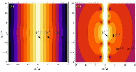
The result (67) is quite remarkable, because it predicts that the Hertzian potential, and hence the electromagnetic fields, varies with simply as , and hence the radiated field is simply guided along , without any form of decay. Moreover, is strongly localized in the vicinity of the -axis, within a spatial region whose characteristic diameter is determined by . It should be mentioned that is actually singular over the -axis (it has a logarithmic singularity). Such a singularity occurs because of the adopted -function model for the lumped voltage generator (also because the macroscopic model effectively assumes infinitesimal wire separation: ). The singularity disappears if one considers a less localized model for the discrete source, e.g. if is replaced by , where is some function of concentrated near the origin. Even for such a source, the electromagnetic fields are characterized by a non-diffractive pattern. This is explained by the “canalization” properties of the wire medium, which enable the transport of the near-field with no diffraction.Belov et al. (2006); Silveirinha et al. (2007) As far as we could check, the inverse Fourier transform of the second addend of (64), i.e. the contribution of the TM mode when , cannot be written in terms of the standard special functions, and hence it needs to be calculated numerically using (56). In Fig. 3, we plot the contour plots of , for the same example as in Fig. 2. It is seen that when (Fig. 3a), i.e. below the effective plasma frequency, the fields are strongly concentrated close to the -axis, and are guided away from the source with no diffraction. The contribution from the mode appears to be residual. On the other hand, above the plasma frequency (Fig. 3a), there are clearly two distinct emission channels, one associated with the TEM mode and another with the TM mode.
IV Nonlocal Dielectric Function Approach
The objective of this section is to prove that the radiation problem in an unbounded uniform structure can be as well solved using the standard nonlocal dielectric function formalism.Maslovski and Silveirinha (2009); Belov et al. (2003); Silveirinha (2006b) The case of a stratified structure, which can be easily handled with the theory of Section III, is out of reach of the nonlocal framework (it could however be handled with a combination of mode matching and additional boundary conditions,Silveirinha (2006a); Maslovski et al. (2010) but a detailed discussion of it is out of the scope of this paper).
In a spatially dispersive medium, the Maxwell equations may be written in a compact form in the space domain as follows:
| (68) | ||||
| (69) |
where the dyadic operator represents the effective dielectric function of the material. Notice that in the space domain the effective dielectric function should be regarded as a function of the gradient . This contrasts with the formulation of Section II where all the structural parameters are independent of . It is also possible to write the term as a spatial convolution.Agranovich and Ginzburg (1966) In the spectral (Fourier) domain, in which , in the particular case of the uniaxial wire medium formed by straight wires, the effective dielectric function is Maslovski and Silveirinha (2009); Belov et al. (2003); Silveirinha (2006b)
| (70) |
where , and the rest of the symbols are defined as in Section II. Notice that the effective dielectric function depends explicitly on .
Despite the apparently complicated form of Eqs. (68)–(69), the radiation problem can be readily solved in the spectral domain in case of an unbounded uniform structure. Indeed, by calculating the Fourier transform of both sides of the equations (68)–(69) with respect to all the space coordinates, so that , it is readily found that
| (71) | ||||
| (72) |
where is the Fourier-transformed source term. After some straightforward manipulations, we find that the Fourier transform of the electric field is
| (73) |
and hence the electric field in the space domain can be formally written as
| (74) |
Notice that, at least a priori, in the nonlocal dielectric function framework we can only consider excitations based on an external density of current (Fig. 1a). The characterization of the excitation based on a lumped voltage source requires the knowledge of internal degrees of freedom of the wire medium (e.g., the current along the wires and the additional potential), which are not described by the effective medium model. Nevertheless, ahead we will show that a lumped source can also be modeled by a suitable equivalent .
Next, we obtain the solution of the radiation problem when , or equivalently when . Instead of attempting to calculate the integral (74) directly, we will solve instead (71)–(72) by introducing the Hertz potential . In this manner, we write the Fourier-transformed fields as follows:
| (75) | ||||
| (76) |
This form immediately satisfies (71). From (72) we find
| (77) |
Using (70), after some trivial vector algebra, we obtain
| (78) |
where
| (79) |
Calculating the vector product of (78) by we find that
| (80) |
and therefore, . From this and (78),
| (81) |
For PEC wires , and thus from (79) we have
| (82) |
from which
| (83) |
and, thus,
| (84) |
which is the same as (66), because .
In the general case in which the metal has a plasmonic-type response, . Introducing the notation we obtain from (81)
| (85) |
Calculating the inverse Fourier transform with respect to we find
| (86) |
At first glance this result looks different from (55), but one may verify that , and, similarly, . Thus, we recover (55) with , which corresponds to the case , consistent with our assumptions in the beginning of this section.
Surprisingly, the lumped voltage source in (3)–(4) can be equivalently represented within the nonlocal dielectric function model with some distributed current density in the unbounded wire medium. To show this, we consider the Fourier-transformed equations (3)–(4) (for simplicity we let ), from which the Fourier-transformed current can be expressed as
| (87) |
When this expression is substituted into the Fourier-transformed equations (1)–(2), the -proportional term of (87) is combined with the term which results in the spatially dispersive permittivity (70), and the -proportional term occurs as an additional external current density
| (88) |
Therefore, applying the inverse Fourier transform, we find that
| (89) |
where . Thus, a lumped voltage source inserted into a wire of the unbounded uniaxial wire medium (with PEC wires, ) may be equivalently represented with a line of -directed wave-like current (89). It is curious to note that while the lumped voltage source excitation is localized at the origin, the equivalent current density is distributed over the entire -axis. At first sight, this may look inconsistent with causality. However, it is simple to verify that such a current is just a wave emerging from the discontinuity point at . Indeed, if one calculates the inverse Fourier transform of (89) with respect to time, it is found that:
| (90) |
with the velocity of propagation in the host material, and the inverse Fourier transform of . The above formula is manifestly consistent with causality, because the excitation at a given point only depends on the excitation at the origin with a delay .
V Energy conservation in the uniaxial wire medium and Poynting theorem
In what follows, we prove that the formulation based on the introduction of additional variables of Section II, enables formulating an energy conservation theorem and the definition of a Poynting vector in the uniaxial wire medium.
We start with equations (1)–(4) written in time domain. The host permittivity is assumed dispersionless and lossless, and the wires are modeled by a self-impedance of the form , where the parameters and are independent of frequency. For metallic wires with radius standing in air and described by the Drude model with the plasma frequency and the collision frequency , these parameters are and .
Thus, in the time domain the equations (1)–(2) and (3)–(4) may be written as
| (91) | ||||
| (92) |
and
| (93) | ||||
| (94) |
where is the effective EMF of the voltage sources inserted into the wires, per unit length of the wires [e.g., for a lumped source inserted into a wire at , ].
Following a standard procedure, we obtain from (91)–(92):
| (95) |
On the other hand, from (93)–(94) we have
| (96) |
where .
Diving the last relation by and adding it to (95) we obtain the conservation law
| (97) |
where
| (98) | ||||
| (99) | ||||
| (100) | ||||
| (101) |
The vectorial quantity in (97) and (98) may be understood as the Poynting vector in the uniaxial wire medium, and as the volume density of the power transferred by the external sources to the medium. In the absence of loss, i.e. when , the term is univocally identified with the density of stored energy. In contrast, if loss is present, then it is generally impossible to separate the energy storage rate from the energy loss rate when a metamaterial is considered macroscopically.
However, if the microstructure of a metamaterial is known, the stored energy can be found from a consistent physical model that fully describes the processes within a unit volume of the metamaterial. Thus, if we assume that the Drude model is such a consistent model for the dynamics of the free electron plasma in metals, then (99) preserves the meaning of the stored energy density even when . In this case, the quantity has the physical meaning of an instantaneous power loss density.
Evidently, in time-harmonic regime the time-averaged Poynting vector is given by
| (102) |
It can be checked that in the lossless case (), and for the case of fields with a spatial dependence of the form with real-valued this reduces to the formula,
| (103) |
with and defined as in Eq. (70), which is applicable to plane waves in general lossless spatially dispersive media.Agranovich and Ginzburg (1966); Silveirinha (2009b); Costa et al. (2011) The application of the above formula to wire media has been considered in several works.Silveirinha (2009c); Nefedov et al. (2005b)
VI Radiation pattern in the PEC case
Next, we obtain the radiation pattern, directive gain, directivity, and radiation resistance for the case of a short vertical dipole radiating in a wire medium formed by PEC wires (Fig. 1a). We do not discuss in details the case wherein the metamaterial is excited by a lumped voltage source, because as discussed in Section III.3 in such a scenario the radiated field is guided along the -axis with no decay. In particular, this implies immediately that the directivity in such a configuration is infinite.
VI.1 Asymptotic form of the radiated fields
To begin with, we obtain the asymptotic form of the field radiated by a short vertical dipole () embedded in a wire medium formed by PEC wires when . Evidently, from the results of Section III.3, unless the frequency of operation is larger than the plasma frequency of the effective medium the radiated fields will decay exponentially away from the source. Hence, in what follows we assume that , so that in Eq. (66). Substituting (66) into Eqs. (6)–(7), it can be easily checked that
| (104) | ||||
| (105) |
where the symbol indicates that the identities are asymptotic (), , and define an orthogonal reference system associated with the usual spherical coordinate system . As seen, unlike what happens in an isotropic medium, the electric far field has a radial component. The amplitude of the electromagnetic fields varies asymptotically as , and with .
Similarly, substituting (66) into Eqs. (3)–(4) and (11), it is found that the asymptotic forms of the current and additional potential are
| (106) | ||||
| (107) |
Thus, from (105) and (107), we see that the time averaged Poynting vector (102) in the far-field is
| (108) |
Straightforward calculations show that the Poynting vector only has a radial component:
| (109) |
Hence, in part surprisingly, it is seen that a short vertical dipole embedded in a wire medium radiate energy along the direction of vibration, i.e. along the -axis! Moreover, in the limit the radiation pattern becomes isotropic: . Note, however, that for , we have and thus the Poynting vector vanishes in the far-field. However, slightly above the emission of radiation is certainly possible. Notice also that in the limit where , we recover the far-field of a short vertical dipole embedded in a dielectric with permittivity .
VI.2 The radiation intensity, directive gain, directivity, and radiation resistance
The radiation intensity of the short vertical dipole, , is given by
| (110) |
Hence, the power radiated by the dipole, , is such that
| (111) |
The directive gain, , is
| (112) |
Since it can be checked that the direction of maximal radiation is . The directivity of the short vertical dipole is, thus,
| (113) |
which therefore increases from unity (for ) up to in the limit .
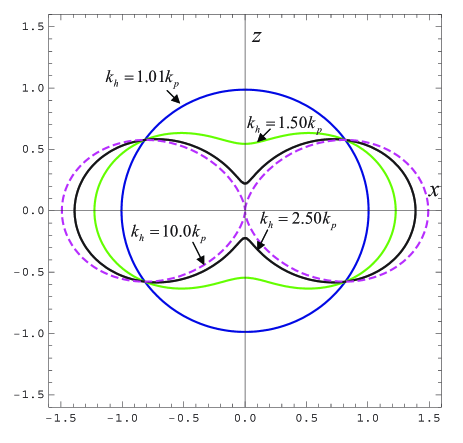
In Fig. 4 we show a polar plot of the directive gain of the short vertical dipole for different frequencies of operation, normalized to the effective plasma frequency. In agreement with the previous discussion, it can be seen that the radiation pattern becomes more directive for increasing values of the frequency, and that for the radiator resembles an isotropic radiator.
To conclude, we note that if the dipole is fed by a current and has infinitesimal height , then the corresponding dipole moment is such that . Thus, it follows that the radiation resistance () of such an elementary source is given by
| (114) |
where is the impedance of the host material.
VII Conclusion
In this work we have studied the radiation of two types of elementary sources embedded in a uniaxial wire medium and derived a general energy conservation theorem. The main challenge of the radiation problem is related to the metamaterial being spatially dispersive. We have shown that the radiation problem can be solved by considering either a nonlocal dielectric function framework or, alternatively, a local model framework based on the introduction of additional variables. However, only the latter approach enables considering stratified media and calculating quantities such as the Poynting vector or the directive gain. It was shown that the emission of radiation by a short dipole in a wire medium has several anomalous features, such as a uniform directive gain near the effective plasma frequency. On the other hand, the radiation by a lumped voltage generator results in a non-diffractive beam that is localized in the vicinity of the -axis, and corresponds to an infinite directivity.
References
- Brown (1953) J. Brown, Proc. IEE 100, 51 (1953).
- Rotman (1962) W. Rotman, IRE Trans. Antennas Propag. 10, 82 (1962).
- Pendry et al. (1996) J. B. Pendry, A. J. Holden, W. J. Stewart, and I. Youngs, Phys. Rev. Lett. 76, 4773 (1996).
- Maslovski et al. (2002) S. I. Maslovski, S. A. Tretyakov, and P. A. Belov, Microw. Opt. Techn. Lett. 35, 47 (2002).
- Pokrovsky and Efros (2002) A. L. Pokrovsky and A. L. Efros, Phys. Rev. B 65, 045110 (2002).
- Belov et al. (2003) P. A. Belov, R. Marques, S. I. Maslovski, I. S. Nefedov, M. Silveirinha, C. R. Simovski, and S. A. Tretyakov, Phys. Rev. B 67, 113103 (2003).
- Silveirinha and Fernandes (2005) M. G. Silveirinha and C. A. Fernandes, IEEE Trans. on Microwave Theory and Tech. 53, 1418 (2005).
- Simovski and Belov (2004) C. R. Simovski and P. A. Belov, Phys. Rev. E 70, 046616 (2004).
- Nefedov et al. (2005a) I. S. Nefedov, A. J. Viitanen, and S. A. Tretyakov, Phys. Rev. E 71, 046612 (2005a).
- Nefedov et al. (2005b) I. S. Nefedov, A. J. Viitanen, and S. A. Tretyakov, Phys. Rev. B 72, 245113 (2005b).
- Silveirinha (2006a) M. G. Silveirinha, IEEE Trans. Antennas Propagat 54, 1766 (2006a).
- Silveirinha (2006b) M. G. Silveirinha, Phys. Rev. E 73, 046612 (2006b).
- Silveirinha (2009a) M. G. Silveirinha, Nonlocal Homogenization Theory of Structured Materials , chapter in Theory and Phenomena of Artificial Materials vol. 1 (edited by F. Capolino) (CRC, 2009a).
- Silveirinha and Fernandes (2008) M. G. Silveirinha and C. A. Fernandes, Phys. Rev. B 78, 033108 (2008).
- Luukkonen et al. (2009) O. Luukkonen, M. G. Silveirinha, A. B. Yakovlev, C. R. Simovski, I. S. Nefedov, and S. A. Tretyakov, IEEE Trans. Microwave Theory Tech. 57, 2692 (2009).
- Yakovlev et al. (2009) A. B. Yakovlev, M. G. Silveirinha, O. Luukkonen, C. R. Simovski, I. S. Nefedov, and S. A. Tretyakov, IEEE Trans. Microwave Theory Tech. 57, 2700 (2009).
- Maslovski and Silveirinha (2009) S. I. Maslovski and M. G. Silveirinha, Phys. Rev. B 80, 245101 (2009).
- Nefedov (2010) I. S. Nefedov, Phys. Rev. B 82, 155423 (2010).
- Ikonen et al. (2006) P. Ikonen, M. Karkkainen, C. Simovski, P. Belov, and S. Tretyakov, IEE Proc.-Microw. Antennas Propag. 153, 163 (2006).
- Lovat et al. (2006) G. Lovat, P. Burghignoli, F. Capolino, D. R. Jackson, and D. R. Wilton, IEEE Trans. Antennas Propagat. 54, 1017 (2006).
- Burghignoli et al. (2008a) P. Burghignoli, G. Lovat, F. Capolino, D. R. Jackson, and D. R. Wilton, IEEE Trans. Antennas Propagat. 56, 1329 (2008a).
- Burghignoli et al. (2008b) P. Burghignoli, G. Lovat, F. Capolino, D. R. Jackson, and D. R. Wilton, IEEE Trans. Microwave Theory Tech. 58, 1112 (2008b).
- Agranovich and Ginzburg (1966) V. M. Agranovich and V. Ginzburg, Spatial Dispersion in Crystal Optics and the Theory of Excitons (Wiley-Interscience N.Y., 1966).
- Costa et al. (2011) J. T. Costa, M. G. Silveirinha, and A. Alu, Phys. Rev. B 83, 165120 (2011).
- Maslovski et al. (2010) S. I. Maslovski, T. Morgado, M. G. Silveirinha, C. S. R. Kaipa, and A. B. Yakovlev, New J. Phys. 12, 113047 (2010).
- Silveirinha et al. (2007) M. G. Silveirinha, P. A. Belov, and C. R. Simovski, Phys. Rev. B 75, 035108 (2007).
- Sakoda (2001) K. Sakoda, Optical Properties of Photonic Crystals (Springer-Verlag (Berlin, Heidelberg), 2001).
- Belov et al. (2006) P. A. Belov, Y. Hao, and S. Sudhakaran, Phys. Rev. B. 73, 033108 (2006).
- Silveirinha (2009b) M. G. Silveirinha, Phys. Rev. B 80, 235120 (2009b).
- Silveirinha (2009c) M. G. Silveirinha, New J. Phys. 11, 113016 (2009c).