10.1080/09500831003800863 \issn1362-3036 \issnp0950-0839 \jvol90 \jnum8 \jyear2010 \jmonthAugust
Theory of ultrathin films at metal-ceramic interfaces
Abstract
A theoretical model for understanding the formation of interfacial thin films is presented, which combines density functional theory calculations for interface energies with thermodynamic modeling techniques for multicomponent bulk systems. The theory is applied to thin film formation in VC-doped WC-Co cemented carbides. It is predicted that ultrathin VC films may exist in WC/Co interfaces at the high temperature sintering conditions where most of the WC grain growth occurs, which provides an explanation of the grain growth inhibiting effect of VC additions in the WC-Co system.
keywords:
interface energy; interface structure; first-principles calculations; cemented carbides; grain growth inhibitors1 Introduction
Ultrathin films are essential for many applications in nanoscale science and technology. Considerable scientific interest is devoted to thin oxide films at metal surfaces [1, 2, 3], for which applications are found in catalysis, semiconductor devices as well as mechanical wear and corrosion protection. Correctly assessing the thermodynamic stability of such films is an important issue [4]. New thin film surface alloys have been discovered and the stability of nano-sized patterns in the ultrathin films investigated with respect to strain and chemical effects [5, 6]. Formation of ultrathin films is also observed in metal-ceramic materials after sintering of nanoparticles into a bulk nanocrystalline material [7].
In this Letter, we consider an interface between two dissimilar materials, a metal-ceramic interface, and the propensity to form, at the interface, an ultrathin film of a secondary phase, whose corresponding bulk phase is thermodynamically unstable. We develop a model for the thin film formation and stability as function of temperature and show that it can be stabilized by interfacial effects.
For modeling of interfaces with complex bonding such as metal-ceramic interfaces, first-principles calculations in the framework of density functional theory (DFT) has proved to be a very useful tool [8, 9, 10]. However, phase stabilities at high temperatures are cumbersome to predict with sufficient accuracy using DFT [11] and therefore we combine DFT calculations with driving forces of nucleation from well-developed thermodynamic modeling techniques [12]. These modeling techniques describe bulk phases but lack information on interfacial effects.
We apply the developed methodology to WC-Co cemented carbides. These materials are produced by means of powder metallurgy, where powders of carbides and metal Co are sintered together into a hard and dense material with excellent mechanical properties. The materials are used in cutting and wear resistant tools and are of considerable industrial importance. Much effort has been invested in developing nanostructured cemented carbides by reducing the mean WC grain size in the finished product, because a fine and homogeneous microstructure has superior mechanical properties [13]. To control the microstructure and retain a fine grain size throughout the sintering, dopants in the form of VC, , TiC, TaC or NbC powders are added, of which VC has proved to be the most effective inhibitor in ultrafine alloys [14]. The grain growth inhibiting effect of the dopants is well established, whereas the inhibiting mechanism on the atomic scale is not understood. Experimental high-resolution electron microscopy (HREM) studies [15, 16, 17, 18, 19] have shown the existence of V- and Cr-rich films of cubic carbide structure at WC/Co interfaces in VC- and -doped materials, respectively, at low temperatures, after liquid phase sintering and cooling. In order to predict the possible growth inhibiting effect of such films, it is decisive to determine whether these can exist at high temperature liquid phase sintering conditions, where most of the grain growth occurs and where HREM cannot be applied.
2 Model
2.1 General description
The interface energy can be expressed as the excess Gibbs energy per unit interface area due to the presence of an interface [20],
| (1) |
is the Gibbs energy for the entire considered system, which contains an interface of area . is the number of atoms in the system of component with a corresponding chemical potential determined by the reservoirs with which the system is in equilibrium. In the present case, the reservoirs are stoichiometric WC and a binder phase. The latter consists of mainly Co (and will be denoted “Co”) but also of dissolved W, C, and M atoms, where M = V, Cr, Ti, etc. depending on the doping.
We consider the propensity to form a thin film consisting of layers of carbide phase, here denoted MC, at the interface between WC and the binder phase. For sufficiently thick films, the interface can be regarded as split into a WC/MC interface and a MC/Co interface separated by a slab of MC. The energy for such a film-covered interface can then be decomposed as
| (2) |
where () is the interface energy between WC and MC (MC and Co). The last term of Eq. (2) represents the energetic cost per layer of building the MC phase and, thus, increases linearly with the number of layers of the film. For the corresponding energy per formula unit we use the notation , where is the interface area of one formula unit. The energy is the negative driving force of nucleation. Assuming a stoichiometric carbide phase, it equals
| (3) |
where is the Gibbs energy per formula unit of MC and () is the chemical potential of M (C). A positive value of thus implies that the MC phase is unstable. We consider coherently strained thin films and the last quantity of Eq. (2), , is the strain energy per layer needed to bring the film into epitaxy with the underlying WC.
The energy should be compared with the energy of a WC/Co interface not covered by any MC film. The film is stable if and, hence, a positive value of
| (4) |
indicates that film formation is possible. An upper limit of the film thickness is found where the energy of the film-covered interface matches the energy of the uncovered interface, , which yields
| (5) |
If is larger than a few atomic layers, the interface may contain a thin film.
The decomposition of in Eq. (2) is valid only if the film is sufficiently thick, so that the interior of the film is bulk-like and the interface energies are well-defined. For thin films, will deviate from the linear dependence on , which implies that can have a minimum as function of for a finite film thickness. In equilibrium, this optimal film thickness will be attained. A schematic illustration of is given in Figure 1.

2.2 Specific model and method
In the present paper we concentrate on VC-doped WC-Co. Results for other MC dopants will be presented elsewhere [21]. WC has a simple hexagonal lattice structure. After liquid-phase sintering in Co, the WC grains are predominantly delimited by their basal and prismatic surfaces [22]. Here, we focus on the basal surface, which can be either W- or C-terminated. We choose the WC surface and the cubic VC phase to be oriented according to
| (6) |
This orientation relationship between WC and MC has been experimentally established for both V- and Cr-doped WC-Co [18, 23].
Interface calculations are performed using DFT and the current computational methodology has been developed in a series of papers [24, 25, 26]. Computational results have been compared with experimental data [24, 25] and the use of the generalized gradient approximation (GGA) for the exchange-correlation effects within DFT in interface calculations has been motivated [26]. Further computational details can be found in [27].
To model the interfaces, we use standard supercell slab geometries, where the interfaces are made coherent by straining the VC and Co phases to match the WC basal surface. The associated strain energies are minimized by relaxing the interplanar distances to account for the Poisson effect. In the calculation of interface energies, the strain energies are canceled, so that , , and represent the chemical contribution to the interface energy and do not depend on system size.
To define an absolute value of the interface energy, a definite value of the carbon chemical potential is required. Within the two-phase region (WC+Co) of the W-C-Co system, can be varied in a small interval limited by the formation of either graphite or a metal-carbide phase [28]. We assume carbon to be in equilibrium with graphite and use the corresponding computed value for [10].
3 Results and discussion
3.1 Interface energies
In the and directions, the WC and VC phases consist of alternating layers of metal and carbon atoms. Assigning the positions to , to and to with respect to hexagonal lattice vectors in the plane, the stacking sequence for WC is and for VC along and , respectively. We have calculated interface energies for all possible stacking sequences involving the , and positions and varying atomic terminations of the phases. Only stoichiometric VC compounds are considered. To assign a value of , we pick the lowest energy among the different stackings and terminations. The resulting interface energy is found to be slightly negative, [27].
The predicted WC/VC interface structure can be compared with experimental findings. By comparing experimental and simulated HREM images of a WC(0001)/VC(111) interface in a VC-doped WC-Co, a particular interfacial stacking has been suggested [29]. We find that the lowest energy is obtained for [27] which is in complete agreement with the stacking suggested in Ref. [29].
The WC/Co and VC/Co interfaces need to be treated with more concern, since at relevant sintering temperatures, the Co binder is in its liquid phase. A solid-liquid interface energy is usually considered as stemming from two separate parts (see, e.g. [30]): a chemical contribution due to differing atomic bonding at the interface, and a structural contribution due to disturbance of the liquid’s structure caused by the interface. One should notice, that only the difference between the two interface energies and enters into the expression (4) for the key quantity . Therefore, the geometrical similarity of the WC(0001) and VC(111) surfaces implies that structural contributions to will to large extent cancel.
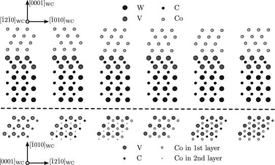
We choose to model the WC/Co and VC/Co interfaces in the same geometry as the WC/VC interface, which means that we are effectively modeling WC(0001)/Co(111) and VC(111)/Co(111) interfaces with different Co stackings. Following the preceding argument, we do not expect the particular choice of Co orientation to influence in any decisive way, although existing experimental observations of this orientation between WC and solid Co [31, 32] do motivate its use as model geometry. At high temperatures, the motion of liquid Co atoms will constantly change the atomic structure at the interface. Therefore, we use a mean value of energies for different stackings of Co in the interface to approximate and , respectively. In Figure 2 we depict the six different atomic arrangements of Co used in calculating the mean energy of the carbide/Co interface. The resulting value for the interface energy can be regarded as a good approximation for an incoherent interface [33]. The termination of the WC or VC slabs (metallic or C) is consistently chosen to yield the lowest mean interface energy.
We find that for WC/Co, the interface is C-terminated with an energy [27]. For VC/Co, the interface is V-terminated with [27]. The resulting difference in interface energy is , which we henceforth will assume to be temperature independent.
The final result of does not strongly depend on the choice of averaging of the various Co stackings in the interfaces. For instance, by following the above procedure but disregarding the two most high-energetic configurations in each interface, increases by . The impact on due to ordering of the liquid Co atoms in the vicinity of the WC or VC interfaces is therefore expected to be maximally of this size. Temperature-dependent deviations from our estimation of may arise from differences in the vibrational spectrum of V, W, and C atoms at the interface as compared with their respective reference states. Following the procedure of Reuter and Scheffler [34], we estimate this effect to be maximally . Considering both these effects, we expect to be determined within an accuracy of . By accounting for a mixed carbide layer instead of the stoichiometric VC compounds considered so far, further entropic effects are introduced (see below).
3.2 Thin film energy and composition
In addition to , the energetic costs, and , to build the VC thin films are needed to predict stability. To compress VC from its calculated equilibrium lattice parameter in the interface, , to the calculated WC lattice parameter, , an energy of only ( per VC formula unit) is required.
The driving force of nucleation, , depends sensitively on the temperature and composition of the system. The most stable cubic carbide is not stoichiometric VC, but a mixed phase. In its at experimentally measured composition, V constitute 75% and W 23% of the metallic atoms and the C vacancy concentration is 11% [28]. To determine the driving force of nucleation we have used the Thermocalc software [12] with a database for Cr and V additions in the W-C-Co system [28]. The database has been assessed from experimental observations using the Calphad method and models temperature dependent Gibbs energies of the phases occurring in the W-C-Co system.
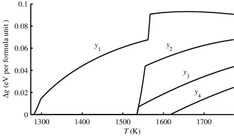
In Figure 3, the negative driving force of nucleation for a phase of optimal composition with respect to Gibbs energy in a W-C-Co-V system in equilibrium with WC and graphite is given as a function of temperature for varying V/Co atomic ratio . For low temperatures, for all considered doping levels, meaning that stable precipitates exist at these chemical conditions. The sharp increase of at temperatures around 1550 K is due to the melting of the binder phase, which significantly increases its solubility of V. At the doping levels and of Figure 3, the thermodynamic calculation (which lacks any model for interface stabilization) predicts that all phase would dissolve as the binder melts. A discontinuous change in the slope of is also found near for . This change is associated with the transition of the solid Co binder from its ferro- to paramagnetic phase. We conclude that for relevant doping concentrations, varies between 0 and 0.1 eV (corresponding to 0 and per layer of ).
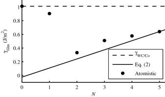
We can now summarize our results for the propensity of thin film formation. In Figure 5, the solid line corresponds to the result from Eq. (2) for VC. Here, we set , which is a reasonable choice based on the results from our thermodynamic modeling at relevant sintering temperatures. With this value of , Eq. (5) suggests that stable films of thickness less than may exist.
In the interface calculations, we have approximated the film carbide phase with a stoichiometric VC phase. The real film may well have a composition similar to the bulk phase, though finding the optimal composition would require numerous large interface calculations. To assess the effect of composition, we have performed a calculation for a mixed phase, whose composition is close to the experimentally measured one of bulk [28]. We obtain [27] and, therefore, we expect that for the true composition, the interfacial effect will further stabilize the thin film.
3.3 Explicit atomistic layer-by-layer treatment
The expression for in Eq. (2) is only valid if the film is sufficiently thick. For thinner films, the details of the atomic layer-by-layer structure has to be taken into account. We have therefore explicitly modeled the atomic layer-by-layer structure of thin films of cubic VC at the WC/Co interface. The number of possible stacking sequences of VC in the WC/VC/Co interface is large, but can be decreased by omitting obviously high-energetic configurations. In total, we have considered 76 different VC stacking sequences with six corresponding Co stackings for each of these [27].
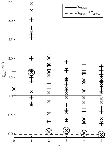
In Figure 4, the energy of a WC/Co interface containing a VC film is given as a function of the number of metallic V layers in the film for different VC stacking sequences. The results for the stackings corresponding to the minimal energy in the WC/VC interface described earlier are circled. In the plot, we show the result without adding any contribution from the energetic cost per layer to build the thin film (). The result should then converge to for sufficiently thick films. We find that the result is close to the asymptotic value already for two V layers, while the result for one V layer deviates both energetically and structurally with being the optimal stacking in this case. The optimal structure in the case of two V layers is depicted in Figure 2.
Our final results are presented as circles in Figure 5, where we again set . To calculate , we take for each number of V layers the minimum energy among the stackings and terminations presented in Figure 4 and add . The fast convergence of the interface energies toward the asymptotic value of Eq. (2) implies that a thin film with two V layers will be the most stable configuration for a rather wide interval of , . For no value of will one V layer be the most stable configuration. With the values used in Figure 5, we find that the interface with a VC film is favored by compared to the interface without segregated VC. This value lies well outside our estimated error bound of indicating that in equilibrium, the WC(0001) surface is indeed covered by VC.
Our prediction of a few stable V layers agrees very well with HREM imaging [18, 19, 29, 7], where thin films on WC(0001) in VC-doped material are seen to have a thickness of two and sometimes a few additional metallic layers. An interpretation of the additional layers is that they precipitate as during cooling. The VC-covered surface is also a likely nucleation site for further growth of the VC phase, which sometimes builds up as a precipitate on WC(0001) during cooling [18, 29].
3.4 Grain growth inhibiting effect
It is generally believed that the rate limiting step of grain growth in WC-Co systems is the dissolution and/or reprecipitation reactions occuring at WC/Co interfaces. Several authors have therefore attributed the growth inhibiting effect of V to a proposed interference with these reactions either through blocking active growth centers at the WC surface [35, 36] or through the presence of segregated V at the WC surface [15, 19], which would hinder W diffusion into or out of the WC grain. Our prediction that ultrathin VC films may be present and stable also at liquid-phase sintering temperatures is supportive of the latter explanation.
4 Conclusions
We have developed an atomistic model for understanding thin film formation at interfaces in bulk composite materials. We combine extensive density functional theory (DFT) calculations for interfaces and thin films with thermodynamic modeling techniques for multicomponent systems. The latter technique is used to obtain relevant chemical potentials for the various components as function of temperature and doping conditions.
The theory is applied to thin film formation in VC-doped WC-Co cemented carbides. It is predicted that under realistic doping conditions, ultrathin films may exist at high temperature liquid phase sintering conditions where most of the grain growth occurs.
By explicit DFT modeling of the thin films as function of the number of atomic layers, we find that the most stable configuration consists of only two V layers over a large temperature range and we show how the atomistic picture approaches the thick film limit with increasing number of layers.
The films, whose corresponding bulk phase is thermodynamically unstable, are stabilized by interfacial effects. Compared with the original interface in the absence of a thin film, there is an energy gain associated with the creation of the two sub-interfaces involved in the thin film formation, which more than compensates for the energetic cost of the thin film itself.
In conclusion, our results explain the formation of VC films in WC/Co interfaces. The presented method can be applied to theoretically assess the stability of other carbide films in WC/Co interfaces.
Acknowledgments
Financial support from the Swedish Research Council, Sandvik and Seco Tools is gratefully acknowledged. Computations have been performed on SNIC resources. We thank Susanne Norgren, Sandvik Tooling, for providing thermodynamic calculations.
References
- [1] G. Kresse et al., Science 308 (2005), p. 1440.
- [2] J. Rogal, K. Reuter, and M. Scheffler, Phys. Rev. Lett. 98 (2007), p. 046101.
- [3] C. Freysoldt, P. Rinke, and M. Scheffler, Phys. Rev. Lett. 99 (2007), p. 086101.
- [4] C.T. Campbell, Phys. Rev. Lett. 96 (2006), p. 066106.
- [5] G.E. Thayer et al., Phys. Rev. Lett. 86 (2001), p. 660.
- [6] V. Ozoliņŝ, M. Asta, and J.J. Hoyt, Phys. Rev. Lett. 88 (2002), p. 096101.
- [7] S. Lay, M. Loubradou, and P. Donnadieu, Adv. Eng. Mater. 6(10) (2004), p. 811.
- [8] M.W. Finnis, J. Phys.: Condens. Matter 8 (1996), p. 5811.
- [9] S.V. Dudiy, J. Hartford, and B.I. Lundqvist, Phys. Rev. Lett. 85 (2000), p. 1898.
- [10] M. Christensen et al., Phys. Rev. Lett. 94 (2005), p. 066105.
- [11] P.E.A. Turchi et al., CALPHAD 31 (2007), p. 4.
- [12] B. Sundman, B. Jansson, and J.O. Andersson, CALPHAD 9 (1985), p. 153.
- [13] Z.Z. Fang and H. Wang, Int. Mater. Rev. 53 (2008), p. 326.
- [14] W.D. Schubert, A. Bock, and B. Lux, Int. J. Refract. Met. Hard Mater. 13 (1995), p. 281.
- [15] A. Jaroenworaluck et al., J. Mater. Res. 13(9) (1998), p. 2450.
- [16] T. Yamamoto, Y. Ikuhara, and T. Sakuma, Sci. Technol. Adv. Mater. 1 (2000), p. 97.
- [17] T. Yamamoto et al., J. Mater. Sci. 36 (2001), p. 3885.
- [18] S. Lay, S. Hamar-Thibault, and A. Lackner, Int. J. Refract. Met. Hard Mater. 20 (2002), p. 61.
- [19] S. Lay, J. Thibault, and S. Hamar-Thibault, Philos. Mag. 83(10) (2003), p. 1175.
- [20] A.P. Sutton and R.W. Balluffi Interfaces in Crystalline Materials, Oxford University Press, Oxford, 1996.
- [21] S.A.E. Johansson and G. Wahnström (2010), in preparation.
- [22] H.E. Exner, Int. Met. Rev. 24(4) (1979), p. 149.
- [23] A. Delanoë et al., J. Cryst. Growth 270 (2004), p. 219.
- [24] M. Christensen, S. Dudiy, and G. Wahnström, Phys. Rev. B 65 (2002), p. 045408.
- [25] M. Christensen and G. Wahnström, Phys. Rev. B 67 (2003), p. 115415.
- [26] M. Christensen and G. Wahnström, Acta Mater. 52 (2004), p. 2199.
- [27] See the online supplementary material for details on the DFT calculations.
- [28] K. Frisk and A. Markström, Int. J. Mater. Res. 99 (2008), p. 287.
- [29] S. Lay, S. Hamar-Thibault, and M. Loubradou, Interface Sci. 12 (2004), p. 187.
- [30] R. Warren, J. Mater. Sci. 15 (1980), p. 2489.
- [31] K. Mohan and P.R. Strutt, Nanostruct. Mater. 7(5) (1996), p. 547.
- [32] V. Bounhoure et al., J. Mater. Sci. 43 (2008), p. 892.
- [33] M. Christensen et al., Acta Mater. 55 (2007), p. 1515.
- [34] K. Reuter and M. Scheffler, Phys. Rev. B 65 (2001), p. 035406.
- [35] A. Bock, W.D. Schubert, and B. Lux, Powder Metall. Int. 24 (1992), p. 20.
- [36] M. Kawakami, O. Terada, and K. Hayashi, J. Jpn. Soc. Powder Powder Metall. 51 (2004), p. 576.
See pages 1 of Supplement.pdf See pages 2 of Supplement.pdf