Electric field control of the magnetic chiralities in ferroaxial multiferroic RbFe(MoO4)2
Abstract
The coupling of magnetic chiralities to the ferroelectric polarisation in multiferroic RbFe(MoO4)2 is investigated by neutron spherical polarimetry. Because of the axiality of the crystal structure below = 190 K, helicity and triangular chirality are symmetric-exchange coupled, explaining the onset of the ferroelectricity in this proper-screw magnetic structure — a mechanism that can be generalised to other systems with “ferroaxial” distortions in the crystal structure. With an applied electric field we demonstrate control of the chiralities in both structural domains simultaneously.
Multiferroic materials, in which ferroelectricity and magnetic order coexist, are attracting conspicuous interest as candidates for novel applications in digital storage devices cheong2007multiferroics_8 . The requirement of having a strong magneto-electric effect has focussed the research on compounds in which ferroelectricity appears as a consequence of magnetic ordering (so called ‘type-II multiferroics’), leading to the realisation that cycloidal multiferroics, such as TbMnO3 kimura2003magnetic_231 and Ni3V2O8 Kenzelmann2006 , exhibit an exceptionally strong cross-coupling between the different types of order. In these compounds the atomic spins rotate within a plane that contains the propagation direction of the incommensurate modulation which connects neighbouring atoms and .
A phenomenological theory based on symmetry analysis of the magnetic and ferroelectric order parameters established that the magnetoelectric coupling has a trilinear form in the free energy Lifshitz , leading to a polarisation given by mostovoy2006ferro_113 . A number of microscopic theories have been proposed that respect these symmetry constraints for the canonical multiferroic materials Sergienko2006role_204 ; katsura2005spin .
An intense experimental effort and a refined understanding of the symmetry requirements for spin-driven ferroelectricity have expanded the range of candidate multiferroic materials. An interesting line of research has developed specifically on magnetochiral or proper-screw systems, in which the atomic spins rotate perpendicularly to the propagation direction of the screw arima2007ferroelectricity_115 ; the model in ref. mostovoy2006ferro_113, predicts no polarisation in this case. One mechanism that can lead to electrical polarisation in a proper-screw magnetic structure is the coupling to structural axiality (ferroaxial coupling) Johnson2011 . A crystal structure can be considered ‘axial’ if there exists a structural distortion that is unchanged by inversion and makes the two senses of rotation (clockwise or counterclockwise) about an axial vector distinguishable. As pointed out in ref. Johnson2011, , the magnetic helicity can be coupled phenomenologically to the electric polarisation and structural axiality to create a trilinear form, , which is invariant under spacial inversion and time reversal. Very recently, “giant” magnetically-induced ferroelectricity has been reported in the ferroaxial system CaMn7O12 JohnsonCaMn7O12 .
RbFe(MoO4)2 (RFMO, ferroaxial below 190 K) is an extremely interesting system to test the interplay between ferroaxiality, magnetism and ferroelectricity. Below K, it orders magnetically in a complex structure that possesses both helicity and triangular chirality (see below), becoming ferroelectric at the same temperature kenzelmann2007direct_160 . Yet, its layered crystal structure and exchange pathways are sufficiently simple for it to be considered the “hydrogen atom” of ferroaxial multiferroics. In previous work, it has been suggested that the 120∘ magnetic structure in each layer is in itself sufficient to break inversion kenzelmann2007direct_160 ; plumer1991chirality_267 . Here, we demonstrate that the axiality and magnetic helicity also play a crucial role in the onset of ferroelectricity. We show that the helicity and triangular chirality are in fact coupled together in the free energy by the axial distortion, and we present data that show switching of both parameters simultaneously with an applied electric field.
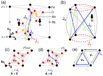
RFMO undergoes a structural transition at K in which the MoO4 tetrahedra rotate (Fig. 1), lowering the symmetry from to (ferroaxial point group ) inami2007neutron_116 ; waskowska2010temp_159 . Below the Fe spins (one per unit cell) order magnetically in the plane in a 120∘ structure, and rotate in a helix between one plane and the next with an incommensurate propagation along (, here always chosen to be positive). Fig. 1(a) shows a unit cell of RFMO with the location of the MoO4 tetrahedra indicated (oxygen atoms mediate the relevant exchange paths — see below). One can see that there is a MoO4 tetrahedron above (or below) each magnetic triangle. We define triangles as “positive” (“negative”) if they are associated with a tetrahedron pointing along the positive (negative) direction [this is indicated by the two unit vectors and in fig. 1(a)]. In plan view, one can rotate the structure in such a way that all the “positive” triangles point “up” the page [this orientation is depicted in Figs.1(c)–1(e)]. We define a staggered triangular chirality (a parity odd quantity) as . In other words, if the spins rotate counterclockwise as one circumscribes counterclockwise a “positive” triangle of Fe spins (with a tetrahedron at its centre); otherwise. The magnetic helicity is defined as usual as for a right- and left-handed magnetic screw, respectively. There are two possible magnetic propagation vectors: for and for , leading to distinct sets of peaks in the magnetic scattering for the two different combinations of chiralities.
Fig. 1(a) shows a unit cell of RFMO with the location of four exchange paths (mediated by the MoO4 oxygens) indicated. The super-superexchange terms across the prismatic faces, and , are equal by symmetry in but become distinct in , so that the difference ( is proportional to the amplitude and sign of the ferroaxial distortion [Figs.1(c) and 1(d)]. Figs. 1(b) and 1(e) show the effect of the ferroaxial rotation on the exchange paths. Assuming the 120∘ structure as given, the symmetric-exchange energy per Fe ion is
| (1) |
where doesn’t depend on the magnetic chiralities. Minimising with respect to results in
| (2) |
We arrive here at our first important result: in the presence of a ferroaxial crystal structure, adjacent 120∘ triangular magnetic planes will rotate with respect to each other, forming a helix, without the need for antisymmetric or inter planar next-nearest neighbour interactions. In a real crystal, both ferroaxial domains will be present with roughly equal populations (one with , the other with ). Therefore, the lowest energy magnetic configurations will depend on the ‘axiality’ of the domain in question. Notating the chiralities of a particular magnetic structure as , eqn. (1) implies that states will be lower in energy than if , or vice versa for . One important consequence is that each of the two structural axial domains will order with a distinct magnetic propagation vector, say for positive axiality and for negative axiality (the exact combination depends on the sign of the magneto-elastic interaction). Therefore, each set of distinct magnetic peaks ( or peaks) probes a single axial domain.
Spherical neutron polarimetry is an ideal technique to study these magnetic structures and their relationship with the electrical polarisation, since it has the ability to distinguish domains with different chiralities. In the present case the magnetic peaks do not overlap with the nuclear peaks in reciprocal space, so it is possible to calculate the polarisation of the scattered beam purely from the magnetic structure factor blume1963polarization_191 . For this we work in the Blume reference frame, in which the -axis is along the scattering vector , the -axis is vertical, and the -axis completes the right-handed set (see inset to Fig. 2). Magnetic neutron diffraction is only sensitive to the component of perpendicular to , which we write . For a structure with one magnetic ion per unit cell, the th moment (in the unit cell of the lattice vector ) is given by for or structures; and is given by for or , where and are orthogonal unit vectors in the plane of the spins. Thus the magnetic structure factor where is a constant, is the magnetic form factor, and the is determined by the magnetic chiralities (see table 1). Given a fully polarised incident beam directed along , the polarisation measured along is written (). For our geometry, the equations reduce to and
| (3) | |||||
| (4) | |||||
| (5) |
where and . Thus, the sign of the and elements, together with the position of the satellites () uniquely determines the domain population for each of the .
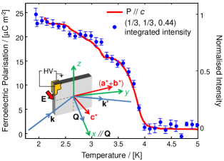
RFMO single crystals were grown by a flux technique using high purity () Rb2CO3, Fe2O3, and MoO3 in a molar ratio of 2:1:6 according to the recipe described in waskowska2010temp_159 . They were heated together in air using a platinum crucible to 825∘C and kept at this temperature for 48 h. The homogenized melt was slowly cooled to 600∘C at a rate of 3∘C/h, followed by a faster rate of cooling to room temperature. Single crystal thin platelets (up to 1 cm in diameter) were separated from the flux, their quality and orientation were checked using an Agilent Technologies SuperNova diffractometer, and pyroelectric currents were measured and integrated to give the ferroelectic polarisation (along ) as a function of temperature (see Fig. 2). Gold contacts were evaporated onto the surfaces and the OrientExpress neutron back-reflection Laue diffractometer Ouladdiaf2006orient_230 at the Institut Laue-Langevin (ILL), Grenoble, France was used to mount the sample with parallel to the -axis (see inset to Fig. 2). This allowed us to access peaks of the form . The contacts were connected to gold wires with silver epoxy to allow high voltage to be applied. An ILL ‘orange’ cryostat provided cooling during the neutron scattering experiment (using a fixed neutron wavelength of 0.825 Å), which was carried out using the CryoPad Tasset1999spherical_222 set-up on beamline D3 at the ILL.
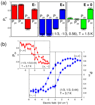
Initially the sample was cooled below , fixing the population of axial structural domains for the rest of the experiment. Fig. 2 shows the temperature dependence of the intensity of the magnetic peak (corresponding to the propagation vector ), which fits the pyroelectric data well and confirms the simultaneous onset of magnetic ordering and ferroelectricity at K. The same sample was cooled in an applied electric field of both 7.5 kV/cm and zero field, and the polarimetry components measured. The results for the peak are shown in Fig. 3(a), together with the calculations (which contain no free parameters) from equations (3) to (5). It is clear that the components and couple to the electric field (slight differences in these components, which should be equal in magnitude, are due to experimental uncertainty).
| , | , | ||
|---|---|---|---|
| , | , | ||
| , | , | ||
| , | , |
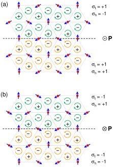
Table 1 lists the magnetic peaks and associated magnetic structure factors originating from different chiral structures. Peaks with propagation vectors and are present with similar intensities, yielding four satellites around each reciprocal lattice node; this shows that the crystal contains a roughly equal population of both axial domains. We examined the behaviour of several magnetic peaks, including at least one from each combination of chiralities, in each of the field coolings. In zero field cooling, the off-diagonal components and for all peaks are zero. This is only possible if the fractions of () and () domains (which have equal and opposite ) are equal, i.e. , and likewise . For positive field cooling, the non-zero off-diagonal terms require that only two of the chirality combinations be present, so that and [Fig. 4(a)]. For negative field cooling, the other two domains are populated, so that and [Fig. 4(b)]. Fig. 3(b) shows the hysteresis in as a function of applied electric field for two magnetic peaks. The peak (resulting from one axial domain) switches between and at whereas the peak (from the other axial domain) switches between and . This confirms that we have direct control over the magnetic structures in both axial domains by using an applied -field.
Based on the geometry of the exchange interactions (Fig. 1), we expect that . We used band structure calculations within the LSDA+U approximation Anisimov-97 ( eV and eV) and the linear muffin-tin orbitals method Andersen-84 to estimate values of the two largest interactions, and . These exchange parameters were calculated as the second derivatives of the energy variation at small spin rotations Liechtenstein and were found to be 1.0 K and 0.3 K, respectively. Using eq. (2) under the assumption that for , together with , we estimate that , leading to a separation in energy between the same magnetic configuration in each of the two axial domains of 0.40 K per spin. Our measured ferroelectric polarisation implies that an electric field of 7.5 kV/cm separates and states [Fig. 3(b)] by K per spin, i.e. 1/1000 of the energy associated with the axial distortion.
Since the direction of the electrical polarisation , as deduced by the direction of , is coupled to the magnetic structure, from symmetry considerations the magnetoelectric free energy can be written as where the axial vector and are constants footnote2 . The two terms in this expression are made proportional to each other by eqn. (1) (since the sign of determines the difference in and ) which imposes that . Our results show that the overall triangular chirality of the entire field-cooled sample is uniform and switches with the electric field, as conjectured by Kenzelmann et al. kenzelmann2007direct_160 , in spite of the axial domain structure. However, as explained above, reversing the electric field actually switches both and simultaneously within a single structural domain (Fig. 4). The two chiral coupling terms to and are both of relativistic origin, since, as we have already shown, domains with opposite polarisation have the same symmetric-exchange energy. However, the two terms rely on different microscopic mechanisms; since the second term is proportional to the axial rotation, a systematic study of isostructural compounds, through measurements or first-principle calculations, could reveal which of the two provides the dominant contribution to the development of the electrical polarisation.
We have demonstrated that the axial distortion of the crystal structure plays a crucial role in stabilising the helical magnetic structure of RbFe(MoO4)2, linking triangular chirality with helicity. By means of neutron spherical polarimetery, we determined uniquely the populations of domains with each of the combinations of helical and triangular chiralities in the two axial domains. By applying an external electric field, the domain population switches between the pairs of magnetic structures that are energetically preferred in each axial domain. The coupling between magnetic structure and electrical polarisation is of relativistic origin, and involves both triangular chirality and helicity, the latter term being proportional to the axial distortion (ferroaxial coupling).
References
- (1) S.-W. Cheong and M. Mostovoy, Nature Materials 6, 13 (2007).
- (2) T. Kimura, T. Goto, H. Shintani, K. Ishizaka, T. Arima, and Y. Tokura, Nature (London) 426, 55 (2003).
- (3) M. Kenzelmann, A. B. Harris, A. Aharony, O. Entin-Wohlman, T. Yildirim, Q. Huang, S. Park, G. Lawes, C. Broholm, N. Rogado, R. J. Cava, K. H. Kim, G. Jorge, and A. P. Ramirez, Phys. Rev. B 74, 014429 (2006).
- (4) L.D. Landau, and E.M. Lifshitz, Statistical Physics, Part 1, 3rd ed. Pergamon, Oxford (1980), p. 466
- (5) M. Mostovoy, Phys. Rev. Lett. 96, 067601 (2006).
- (6) I. A. Sergienko and E. Dagotto, Phys. Rev. B 73, 094434 (2006).
- (7) H. Katsura, N. Nagaosa and A. V. Balatsky, Phys. Rev. Lett. 95, 057205 (2005).
- (8) T. Arima, J. Phys. Soc. Jpn. 76, 073702 (2007).
- (9) R. D. Johnson, S. Nair, L. C. Chapon, A. Bombardi, C. Vecchini, D. Prabhakaran, A. T. Boothroyd, and P. G. Radaelli, Phys. Rev. Lett. 107 137205 (2011).
- (10) R. D. Johnson, L. C. Chapon, D. D. Khalyavin, P. Manuel, P. G. Radaelli, and C. Martin, Phys. Rev. Lett. 108, 067201 (2012).
- (11) M. Kenzelmann, G. Lawes, A. B. Harris, G. Gasparovic, C. Broholm, A. P. Ramirez, G. A. Jorge, M. Jaime, S. Park, Q. Huang, A. Ya. Shapiro, and L. A. Demianets, Phys. Rev. Lett. 98, 267205 (2007).
- (12) M. L. Plumer, H. Kawamura, A. Caillé, Phys. Rev. B 43, 13786 (1991).
- (13) T. Inami, J. Solid State Chem. 180, 2075 (2007).
- (14) A. Waśkowska, L. Gerward, J. Staun Olsen, W. Morgenroth, M. Maczka, and K. Hermanowicz, J. Phys.: Condens. Matt. 22, 055406 (2010).
- (15) M. Blume, Phys. Rev. 130, 1670 (1963).
- (16) B. Ouladdiaf, J. Archer, G.J. McIntyre, A.W. Hewat, D. Brau, and S. York, Physica B: Cond. Matt. 385, 1052 (2006).
- (17) F. Tasset, P. J. Brown, E. Lelievre-Berna, T. Roberts, S. Pujol, J. Allibon, and E. Bourgeat-Lami, Physica B: Cond. Matt. 267, 69 (1999).
- (18) V. I. Anisimov, F. Aryasetiawan, and A. I. Lichtenstein, J. Phys.: Condens. Matt. 9, 767 (1997).
- (19) O.K. Andersen and O. Jepsen, Phys. Rev. Lett. 53, 2571 (1984).
- (20) A. I. Liechtenstein, M. I. Katsnelson, V. P. Antropov, and V. A. Gubanov, J. Magn. Magn. Mater. 67, 65 (1987).
- (21) Note that terms of the form and are forbidden because they are not invariant by the choice of the positive direction, which changes the sign of , , and , but leaves unchanged.