Suppression of magnetism in BiFeO3 ultrathin epitaxial multilayers
Abstract
Preliminary first-principles calculations on the magnetic behavior
of ultra-thin epitaxial multilayers between the BiFeO3
magnetoelectric compound and various types of spacers are
presented. As spacer we have considered i) InP semiconductor, ii)
Fe which is a ferromagnet, and iii) metallic V. In all cases under
study the growth axis of the multilayer was the [001]. Our results
indicate that the magnetic properties are seriously downgraded for
the ultrathin BiFeO3 multilayers independent of the nature of
the spacer and in some cases under study magnetism even vanishes.
More extensive calculations are needed to establish a more clear
view of the physical properties of the interfaces involving the
BiFeO3 compound. The present manuscript completes the study
presented in two recent research articles [K. Koumpouras and I.
Galanakis, J. Magn. Magn. Mater. 323, 2328 (2011);
ibid, J. Spintron. Magn. Nanomater. 1, in press
(2012)].
Keywords: Electronic Structure Calculations, Magnetism,
Multiferroics, DFT, Ferrites
pacs:
75.50.Bb, 75.50.Ee, 75.70.CnI Introduction
Among the most interesting new classes of materials under intense investigation in SpintronicsZutic ; Felser ; Zabel are the so-called multiferroics which combine several ferroic orders like ferromagnetism, ferroelectricity, ferroelasticity etc.Review ; Review5 ; Review6 The compounds combining the electric and magnetic orderReview have several potential applications like magnetic-field sensors and electric-write magnetic-read random-access memories.Hetero ; General1 ; Zhang ; Review7 ; Review8 Magnetic order and ferroelectricity have different originsPicozzi ; Picozzi2 ; General2 and thus the materials exhibiting the magnetoelectric effect are few and the coupling between the magnetic and electric properties is weak. An alternative route to achieve a strong coupling could be the growth of thin film heterostructures and several advances have been made towards the magnetic control of ferroelectricityGeneral3 ; General4 ; Review2 and the electric control of thin film magnetism.Films3 ; Review3 ; Review4
Bismuth ferrite is probably the most studied representative of magnetoelectric materials. Bulk BiFeO3 crystallizes in a perovskite-like pseudocubic structure instead of a ferrite one and is classified as a ferroelectric G-type antiferromagnet.Kiselev Several first-principles calculations have been carried out to study the properties of bulk BiFeO3BiFeO3-Calc and we refer readers to Ref. Palova, for an overview of the literature on this compounds. Since the single-component crystals like BiFeO3 present only a weak magnetoelectric effect, an alternative route to achieve a more strong effect has been proposed to be the growth of heterostructures where epitaxial strain can enhance the phenomenon.Films1 ; Trilayers ; Kovachev ; Yamauchi Thus first-principles calculations of such heterostructures involving alternating layers of BiFeO3 and various spacers can serve as a test-ground to study the behavior of electric and magnetic properties of films. The study of the latter in the case of ultrathin epitaxial films is the aim of the present manuscript.
In a recent publication (Ref. Koumpouras, ) we have presented extended first-principles calculations, employing the Quantum-ESPRESSOQE ab-initio electronic structure method in conjunction with the Generalized-Gradient Approximation (GGA) in the Perdew-Burke-Erzenhof formulation,GGA on the electronic and magnetic properties of BiFeO3 alloy as a function of the lattice constant in the case of the cubic perovskite structure (see figure 1 in Ref. Koumpouras, ). In Ref. Koumpouras2, we have extended this study to cover also the case of Mn substation for Fe. All compounds under study in these two references exhibited significant magnetic properties with spin magnetic moments at the Fe and Mn sites of the order of 3 . In the present contribution we expand these two studies using the same ab-initio method with grids of the same density in the k-space to cover also the case of ultrathin epitaxial films. Although these films are ideal cases and cannot be, with few exceptions, be realized experimentally, they can serve as starting point to understand the interplay between the interface structure and the magnetic properties of BiFeO3 films with other spacers. For completeness we took into account three different spacers to cover different cases of electronic properties at the interface: InP semiconductor, metallic V and ferromagnetic Fe. In Section II we present the structure of the multilayers and the results for the case of the InP spacer, in section III the cases of Fe and V metallic spacers and finally in Section IV we present the main conclusions of our work.
II InP spacer
II.1 Structure of the multilayer
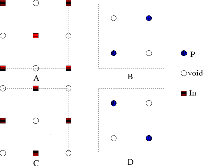
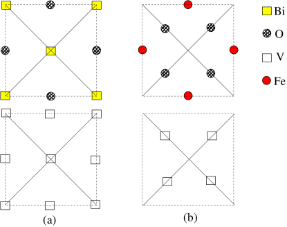
Along the [001] direction BiFeO3 can be considered to consist of alternating layers of BiO and FeO2 as shown in Fig. 1. The in-plane unit cell is a square of the same lattice constant as the cubic unit cell of the bulk BiFeO3. InP crystallizes in the zincblende structure, similar to GaAs, as most of the III-V semiconductors, and has an experimental lattice constants of 5.87 Å. Along the [001] direction, the zincblende structure can be viewed as consisting of alternating pure In and pure P atomic layers as shown in Fig. 2. To fully describe the zincblende structure we have to consider, except the In and P atoms, also the occurrence of vacant sites (voids); there are exactly two no-equivalent voids within the zincblende unit cell. As shown in Fig. 2 along the [001] direction there are not two but four alternating non-equivalent atomic layers. The difference between the A(B) and C(D) layers is that the In(P) atoms have exchanged sites with the voids. This exchange of atomic positions is important since it lead to four non-equivalent interfaces between InP and BiFeO3 in our study. Finally we have to mention that the lattice constant of InP coincides with the BiFeO3 lattice constant multiplied by the square root of two: . Thus as shown in Fig. 1 the diagonal of the BiFeO3 two-dimensional square unit cell can be assumed to be the side of the corresponding unit cell of the InP (denoted with red color in the figure) and thus epitaxial growth between InP and BiFeO3 can be assumed.
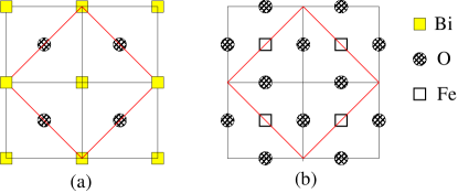
For the InP/BiFeO3 multilayers we studied four different cases with respect to the relative position of the atoms at the interface between the two spacers. Along the growth axis we took into account eight atomics layers which are repeated in the [001] direction. Initially we studied the structure …FeO2//In/P/In/P/BiO/FeO2/BiO/FeO2//In…, and thus in the first case we have two non-equivalent interface in our structure: a P/Bi and an In/Fe ones. A close examination of Figs. 1 and 2 reveals that, in the case just mentioned :(a) with respect to the P/Bi interface P atoms are situated in the diagonal connecting Bi atoms (compare (a) in Fig. 1 with the D layer in Fig. 2), and (2) with respect to the In/Fe interface In atoms are situated in the midpoint between Fe nearest neighbors (take into account A layer in Fig. 2 and combine it with the (b) in Fig. 1).
In the second case under study In and P atoms have exchanged sites with respect to the first case under study and thus now we have along the [001] direction a …FeO2//P/In/P/In/BiO/FeO2/BiO/FeO2//P… structure, i.e. the inequivalent interfaces are now In/Bi and Fe/P. Notice that as in the Fe/In interface in case 1, also in the P/Fe interface, which occurs in case 2, the P atoms at the interface are located in the midpoints between the Fe atoms (if we examine only the in-plane projection of the multilayer) just above the oxygen atoms and this results to vanishing magnetism in case 2 under study as will be discussed later in the next subsection.
As we mentioned above the structure of InP along the [001] direction should be viewed as consisting of four atomic layers (see Fig. 2) since voids play a crucial role in interfaces. If in the two previous cases 1 and 2 we exchange layer A(B) with layer C(D) in Fig. 2 we get two new cases 3 and 4 with different arrangement of the atoms at the interface. In case 3(4), the succession of the atomic layers is similar to case 1(2). When we compare case 1(2) with case 3(4), we conclude that the P(In)/Bi interfaces are similar since the P(In) atoms are now situated at the other diagonal connecting the Bi atoms. Critical is the other In(P)/FeO2 interface since now in case 3(4) the In(P) atoms are located just above the Fe atoms while in case 1(2) they were located above the oxygen atoms at the midpoints between neighboring Fe atoms.
II.2 Results and discussion
In all cases under study our results converged to the ferromagnetic solution independently of the initial conditions and initial arrangement of the spin moments. As in-plane lattice constant we have chosen the Å Å (11.1 a.u.) which is the experimental lattice constant of InP and moreover for the lattice constant of 4.153 Å BiFeO3 exhibits very pronounced magnetic properties.Koumpouras As a result of the epitaxial growth along the [001] axis the lattice constant was 14.182 Å (26.8 a.u.).
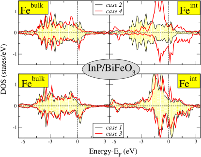
In Fig. 3 we present the density of states (DOS) of the Fe d-orbitals for all four cases under study. We denote as Febulk the Fe atoms within the BiFeO3 spacer and with Feint the Fe atoms located at the interface. We have also to note here that for the multilayer structures under study, we have a complete lift of the degeneracy of the Fe d-orbitals and we cannot refer anymore to the double-degenerated and triple degenerated orbitals as in bulk BiFeO3. In case 2 where we have a P/Bi interface our calculations have converged to a non-magnetic solution. The loss of magnetism in this case should be attributed to the reduced hybridization between the neighboring Fe and P atoms at the interface. The latter have as valence 3p electrons which are less extended in space with respect to the In 5p valence states and do not hybridize with the Fe d-orbitals at the interface. In case I, the d-band is shifted to higher energy values for the spin-down electrons with respect to the spin-up electrons. This is more easy to visualize for the Feint atoms since their hybridization with the p-orbitals of In leads to more pronounced electronic properties (smaller bandwidth with respect to the Febulk atoms and thus more intense picks). The latter is also reflected on the spin magnetic moments presented in Table 1 where the spin magnetic moments are considerable larger for Feint with respect to Febulk.
| Febulk | Feint | |
| Case 1 | 0.357 | 1.158 |
|---|---|---|
| Case 2 | 0 | 0 |
| Case 3 | 0.247 | 0.746 |
| Case 4 | 0.296 | 0.919 |
In Fig. 3 we also present the DOS of the Fe atoms for the cases 3 and 4 where we have changed the positions of the In(P) atoms at the interface. More precisely, as we discussed in the previous section, the In(P) atoms at the interface with FeO are not any more situated above the Fe atoms instead of the O atoms in cases 1 and 2. This leads to increased hybridization also in case 4, where we have a P/Fe interface and now the multilayer converges to a magnetic solution contrary to case 2 where we had a non-magnetic configuration. If we compare cases 1 and 3, where the Fe/In contact appears, we can notice that in case 3 the splitting of the Feint d-bands is smaller due to the alteration in the Fe 3d-In 5p orbitals hybridization resulting also in smaller spin magnetic moments as shown in Table 1. But overall the obtained DOS are similar to the ones obtained for case 1 and presented also in Fig. 3.
III V and Fe spacers
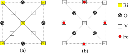
We continue our study using two metallic spacers, ferromagnetic Fe and normal metallic V, instead of InP. Both Fe and V crystallize in the bcc structure. The zincblende structure of InP, if we take into account the vacant sites and ignore the different chemical species, is in reality a bcc one. Thus the structure of the Fe/BiFeO3 and V/BiFeO3 multilayers is similar to the structure of the InP/BiFeO3 where all sites are occupied exclusively by Fe or V atoms. We have studied 5 cases for both multilayers where we have just varied the lattice constant. Case 1 corresponds to the same lattice constant as for InP/BiFeO3 studied in the previous section. Cases 2 and 3 correspond to a uniform compression of the lattice parameter in all directions of 10 and 5 % , respectively, and cases 4 and 5 of a uniform expansion of the lattice parameter of 5 and 10 % , respectively. Our aim is to study the behavior of the magnetic properties upon hyrdrostatic pressure. In cases 1, 4 and 5 we converged to a ferromagnetic solution irrespectively of the initial arrangement of the spin magnetic moments. In contrast in the compressed cases 2 and 3 for Fe/BiFeO3 we could not get convergence while for the case of the V spacer we converged to a non magnetic solution. This behavior stems from the reduced volume around the Fe atoms which leaded to a large compression of the Fe d-orbitals and suppression of magnetism as expected by the magnetovolume effect which has been extensively studied for transition metal atoms. In the multilayers under study we have also two inequivalent interfaces: a V(Fe)/BiO and a V(Fe)/FeO2 contact. In the first interface the four V(Fe) atoms are located within the two diagonals connecting the Bi atoms as shown in Fig. 4a while in the second interface they are located just above the Fe atoms of FeO2 as shown in Fig. 4b.
We will start our discussion concentrating on the Fe atoms within the BiFeO3 spacer in the case of the Fe/BiFeO3 multilayer and in Table 2 we have gathered the Fe spin magnetic moments for both Fe atoms in the inside of the BiFeO3 spacer (Febulk) and at the interface (Feint). As mentioned above for the compressed cases 2 and 3 we were not able to converge to a solution. For case 1 we converged to a non-magnetic solution and for the more expanded lattice parameters (cases 4 and 5) we converged to a magnetic solution. The spin magnetic moments are larger for the more expanded case 5. This behavior is expected by the well studied magnetovolume effect. For the late transition metal atoms like Fe, the spin-splitting of the d-states increases with the atomic volume. Thus as we expand the lattice the tendency to magnetism increases leading to larger spin moments while compression of the lattice eventually leads to loss of magnetism. A similar situation occurs also for the case of V/BiFeO3 but now the tendency to magnetism is stronger for the same lattice parameter. For cases 2 and 3 we converged to a non-magnetic solution while we got a ferromagnetic configuration for case 1 contrary to the Fe/BiFeO3 multilayer. Fe spin magnetic moments are larger for the V spacer but the largest calculated value, which we got for Feint in case 5 as shown in Table 2, is 1.3 almost half the value in pure bulk Fe. Although magnetism is present for the cases with the more expanded lattice constant the magnetic properties are seriously downgraded with respect to pure BiFeO3 bulk crystals.
| V/BiFeO3 | VFe/BiFeO3 | |||
| FeBulk | Feint | FeBulk | Feint | |
| Case 1 | 0.146 | 0.777 | 0 | 0 |
| Case 2 | 0 | 0 | – | – |
| Case 3 | 0 | 0 | – | – |
| Case 4 | 0.269 | 1.252 | 0.224 | 0.620 |
| Case 5 | 0.325 | 1.301 | 0.339 | 0.815 |
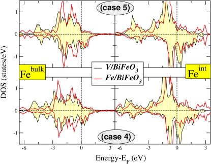
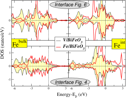
In the case 1 of Fe/BiFeO3, presented in the lower panel of Fig. 7, both Fe atoms within the BiFeO3 spacer are non magnetic and the DOS is the same for both spin directions, while in the case of V/BiFeO3 a small splitting of the d-bands appears in accordance to the spin magnetic moments presented in Table 2. This splitting increases as we move to case 4 and 5 (presented in Fig. 5) following the increase of the spin magnetic moments. We can make two remarks with respect to the presented DOS. First, for the Fe atoms at the interface (Feint) the weight of the d-states is shifted close to the Fermi level with respect to the Febulk atoms as a consequence of the increased hybridization at the interface. Second, if we compare the behavior of the same Fe atom for the same lattice constant in the two multilayers under study, the exchange splitting of the d-bands is larger in the case of the V spacer (spin-up states are deeper in energy and spin-down states higher in energy) in accordance with the larger spin magnetic moments in this case.
III.1 Effect of the change of V(Fe) positions at the interface
In this subsection we present results again for the V/BiFeO3 and Fe/BiFeO3 multilayers for the lattice constant of case 5 for which magnetism is more pronounced. And thus the in-plane lattice constant is 6.46 Å and the out of plane 15.61 Å . The difference with the multilayers studied just above is that we have changed the position of the V(Fe) atoms at the interface. As shown in Fig. 6 the V(Fe) atom at the interface with FeO are now located just above the oxygen atoms of the BiFeO3 spacer and not the Fe ones. The change of the local environment leads to reduced hybridization of d-orbitals of the transition-metal atoms at the interface due to the larger Fe-V(Fe) distance and thus to smaller induced spin magnetic moments in the BiFeO3 layer. For both V/ and Fe/BiFeO3 multilayers the Feint spin magnetic moment is 0.26 , while the Febulk moment is 0.11 for the case of the V spacer and only 0.002 for the case of the Fe spacer. Our discussion on the spin magnetic moments is reflected also on the DOS presented in the upper panel of Fig. 7 where the imbalance between the spin-up and spin-down states is very small. The only noticeable effect is the shift of the Feint d-states between the two multilayers; for the V spacer the Feint states are more concentrated around the Fermi level. The Febulk atoms are shielded from the interface due to the surrounding Bi and O atoms and the DOS is more similar for both type of V and Fe spacers as reflected also on the spin magnetic moments.
III.2 Behavior of V and Fe atoms within the V(Fe)spacer
In this section we will shortly refer to the magnetic properties of the V and Fe atoms within the transition metal spacers. There are four transition metal atoms within each atomic layer and we have 4 atomic layers in our spacer which we count starting from the interface with the FeO2 (we denote it as layer 1) and end with the atomic layer at the interface with BiO. We will start our discussion for the V spacer in the case of the V/BiFeO3 multilayer. V atoms present vanishing spin magnetic moments as shown in Table 3 in all cases under study and only in the case 5 (largest lattice constant under study), do the V atoms in the layer close to the FeO2 layer show a small spin magnetic moment of about 0.13 .
| V/BiFeO3 | ||||
|---|---|---|---|---|
| case 1 | case 4 | case 5 | case 5-II | |
| Layer 1 | 0.016 | -0.010 | -0.003 | -0.003 |
| 0.062 | 0.130 | 0.095 | 0.039 | |
| Layer 2 | -0.005 | 0.015 | 0.016 | 0.007 |
| Layer 3 | -0.015 | -0.003 | -0.004 | 0.015 |
| 0.002 | -0.006 | -0.009 | -0.002 | |
| Layer 4 | -0.005 | 0.005 | 0.010 | 0.003 |
| Fe/BiFeO3 | ||||
| case 1 | case 4 | case 5 | case 5-II | |
| Layer 1 | 0 | -0.026 | -0.129 | -0.110 |
| -0.040 | -0.174 | 0.479 | ||
| Layer 2 | 0 | 0.017 | 0.209 | -0.023 |
| Layer 3 | 0 | -0.005 | -0.021 | -0.022 |
| -0.012 | -0.202 | 0.058 | ||
| Layer 4 | 0 | 0.015 | 0.116 | -0.010 |
Similar is the situation for the Fe spacer where for the two smaller lattice constants we could not even converge our calculations. As shown in Table 3 only for the largest value of the lattice constant we got significant values of the Fe spin magnetic moments, which even for this case, are considerable smaller than the spin magnetic moments of Fe atoms of the BiFeO3 spacer (0.2 for Fe spacer compared to 0.8 for BiFeO3 spacer) and are about one order of magnitude smaller than in bulk Fe.
We have also included in Table 3 the results for the interface structure of Fig. 6, denoted as ”case 5-II” where we have changed the positions of the V(Fe) atoms at the interface. Overall also in this case the magnetic properties of the spacer are not significant. Only in the case of the Fe/BiFeO3 multilayer half the Fe atoms at layer 1 (located at the interface with FeO2) present a significant spin magnetic moment of about 0.5 which is still much lower than the bulk Fe value.
IV Conclusions
We expand our study on the magnetic properties BiFeO3 presented in Refs. Koumpouras, and Koumpouras2, to the case of ultrathin epitaxial multilayers using the Quantum-ESPRESSO first-principles electronic structure method.QE We have studied several cases of these ultrathin epitaxial BiFeO3 multilayers using different types of spacers covering a wide range of electronic materials: InP semiconductor, ferromagnetic Fe and metallic V. Irrespectively of the spacer the magnetic properties of the multilayers were found to seriously degrade due to the low-symmetry of the film and in some cases magnetism vanished completely. Thus ultrathin multilayers of BiFeO3 are not suitable for spintronic applications. More extended calculations covering more thick multilayers and including quantum molecular dynamics are needed in the future to determine in more detail the properties of the interfaces of BiFeO3 with other alloys.
Acknowledgements.
Financial support from the University of Patras (K. Karatehodori 2008 program Nr. C588) is acknowledged.References
- (1) I. Žutić, J. Fabian, and S. Das Sarma, Rev. Mod. Phys. 76, 323 (2004).
- (2) C. Felser, G. H. Fecher, and B. Balke, Angew. Chem. Int. Ed. 46, 668 (2007).
- (3) H. Zabel, Materials Today 9, 42 (2006).
- (4) R. Ramesh and N. A. Spaldin, Nature Materials 6, 21 (2007).
- (5) L. W. Martin, S. P. Crane, Y. -H. Chu, M. B. Holcomb, M. Gajek, M. Huijben, C. -H. Yang, N. Balke, and R. Ramesh, J. Phys.: Condens. Matter 20, 434220 (2008).
- (6) K. F. Wang, J. M. Liu, and Z. F. Ren, Adv. Phys. 58, 321 (2009).
- (7) W. Eerenstein, M. Wiora, J. L. Prieto, J. F. Scott, and N. D. Mathur, Nature Materials 6, 348 (2007).
- (8) M. Gajek, M. Bibes, S. Fusil, K. Bouzehouane, J. Fontcuberta, A. Barthélémy, and A. Fert, Nature Materials 6, 296 (2007).
- (9) Y. Zhang, X. Li, C. Deng, J. Ma, Y. H. Lin, and C. W. Nan, Appl. Phys. Lett. 92, 152510 (2008).
- (10) L. W. Martin, Dalton Trans. 39, 10813 (2010).
- (11) N. A. Spaldin, S. W. Cheong, and R. Ramesh, Physics Today 63, 38 (2010)
- (12) S. Picozzi, K. Yamauchi, B. Sanyal, I. A. Sergienko, and E. Dagotto, Phys. Rev. Lett. 99, 227201 (2007).
- (13) S. Picozzi and C. Ederer, J. Phys.: Condens. Matter 21, 303201 (2009).
- (14) J. M. Rondinelli, M. Stengel, and N. A. Spaldin, Nature Nanotechnology 3, 46 (2008).
- (15) N. Hurr, S. Park, P. A. Sharma, J. S. Ahn, S. Guha, and S. -W. Cheong, Nature 429, 392 (2004).
- (16) T. Lottermoser, T. Lonkal, U. Amann, D. Hohlwein, J. Ihringer, and M. Flebig, Nature 430, 541 (2004).
- (17) S. -W. Cheong and M. Mostovoy, Nature Materials 6, 13 (2007).
- (18) K. Dorr, C. Thiele, J. W. Kim, O. Bilani, K. Nenkov, and L. Schultz, Phil. Mag. Lett. 87, 269 (2007).
- (19) Y. H. Chu, L. W. Martin, M. B. Holcomb, and R. Ramesh, Materials Today 10, 16 (2007).
- (20) Y. H. Chu, L. W. Martin, M. B. Holcomb, M. Gajek, S.-J. Han, Q. He, N. Balke, C.-H. Yang, D. Lee, W. Hu, Q. Zhan, P.-L. Yang, A. Fraile-Rodriguez, A. Scholl, S. X. Wang, and R. Ramesh, Nature Materials 7, 478 (2008).
- (21) S. V. Kiselev, R. P. Ozerov, and G.S. Zhdanov, Sov. Phys. Dokl. 7, 742 (1963).
- (22) J. B. Neaton, C. Ederer, U. V. Waghmare, N. A. Spaldin, and K. M. Rabe, Phys. Rev. B 71, 014113 (2005).
- (23) L. Palova, P. Chandra, and K. M. Rabe, Phys. Rev. B 82, 075432 (2010).
- (24) S. Geprägs, M. Opel, S. T. B. Goennenwein, and R. Gross, Phil. Mag. Lett. 87, 141 (2007)
- (25) A. J. Hatt and N. A. Spaldin, Appl. Phys. Lett. 90, 242916 (2007).
- (26) S. Kovachev and J. M. Wesselinowa, J. Phys.: Condens. Matter 21, 225007 (2009).
- (27) K. Yamauchi, B. Sanyal, and S. Picozzi, Appl. Phys. Lett. 91, 062506 (2007).
- (28) K. Koumpouras and I. Galanakis, J. Magn. Magn. Mater. 323, 2328 (2011).
- (29) P. Giannozzi et al, J. Phys.: Condens. Matter 21, 395502 (2009).
- (30) J. P. Perdew, K. Burke, and M. Ernzerhof, Phys. Rev. Lett. 78, 1396 (1997).
- (31) K. Koumpouras and I. Galanakis, J. Spintron. Magn. Nanomater. 1, in press (2012); Preprint arXiv:1107.4448.