\ethnote {Authlist} G. Dissertori, D. Luckey, F. Nessi-Tedaldi, F. Pauss, R. Wallny \InstfootethInstitute for Particle Physics, ETH Zurich, 8093 Zurich, Switzerland R. Spikings, R. Van der Lelij \InstfootunigeDepartment of Mineralogy, University of Geneva, 1205 Geneva 4, Switzerland G. Arnau Izquierdo \InstfootcernCERN - EN Department, 1211 Geneva 23, Switzerland
A visualization of the damage in Lead Tungstate calorimeter crystals
after exposure to high-energy hadrons
The anticipated performance of calorimeter crystals in the environment expected after the planned High-Luminosity upgrade of the Large Hadron Collider (HL-LHC) at CERN has to be well understood, before informed decisions can be made on the need for detector upgrades. Throughout the years of running at the HL-LHC, the detectors will be exposed to considerable fluences of fast hadrons, that have been shown to cause cumulative transparency losses in Lead Tungstate scintillating crystals. In this study, we present direct evidence of the main underlying damage mechanism. Results are shown from a test that yields a direct insight into the nature of the hadron-specific damage in Lead Tungstate calorimeter crystals exposed to 24 GeV/c protons.
submitted to Elsevier for publication in Nucl. Instr. and Meth. in Phys. Research A
1 Introduction
Detectors now in operation at the Large Hadron Collider at CERN may need to face an increasingly challenging environment after the accelerator upgrade to High-Luminosity running (HL-LHC), that is being planned to start - according to the present schedule - in 2022. While performance requirements will be driven by the physics results obtained at the LHC in the near future, a thorough understanding of the detector behavior is needed, as an input to knowledgeable decisions concerning upgrades.
In this framework, our earlier studies on Lead Tungstate (PbWO4) [1, 2, 3] have established that hadronic showers from high-energy protons [1] and pions [2] cause a cumulative loss of Light Transmission in PbWO4, which is permanent at room temperature, while no hadron-specific change in scintillation emission [3] was seen. The features observed hint at local centers of damage that might be caused by fragments of the heavy elements, Pb and W as the dominant cause of transmission losses. Such fragments can have a range up to 10 m and energies up to 100 MeV, corresponding to a stopping power four orders of magnitude higher than the one of minimum-ionizing particles [1].
The qualitative understanding we gained of hadron damage in Lead Tungstate led us to predict [4] that such hadron-specific damage contributions are absent in crystals consisting only of elements with , which is the experimentally observed threshold for fission [5], while they should be expected in crystals containing elements with . We confirmed the first prediction with measurements [6] that show how hadrons in Cerium Fluoride cause a damage that recovers at room temperature, with none of the features we observed for Lead Tungstate. The second prediction is confirmed by existing proton-damage measurements in BGO [7, 8], in Lead Fluoride and BSO [9], which all contain elements with .
All this indirect evidence is consistent with a mechanism by which the heavy fission fragments deposit a lot of energy along their short track, leaving regions within the crystal where the lattice structure is modified: it can remain disturbed, strained, disordered, or re-oriented. These damage regions have different optical and mechanical properties from the surrounding crystal lattice, and thus they can act as scatterers for light propagating in the crystal, whatever its origin, from scintillation or from an external source.
The mechanism is well known since a long time, and is commonly called ”fission track damage” in literature. In fact, almost a century ago, F. Dessauer formulated the concept of a ”thermal spike” when an incident ion comes to a stop in matter [10]. Later on, L. T. Chadderton and I. McC. Torrens , in their book on the subject [11] , explained how “Along the heated cylindrical track of the fragment the crystalline matter is disturbed, decomposed, or removed. The subsequent arrangement is not necessarily perfect and strain centers or dislocations remain” and ion implantation has become, in recent days, a technique used to change material properties [12].
In this study we present direct, visual evidence that confirms our understanding of hadron damage mechanisms. This will help making informed decisions regarding future calorimeter design or upgrades, to ensure an optimum long-term detector performance.
2 Macroscopic observations
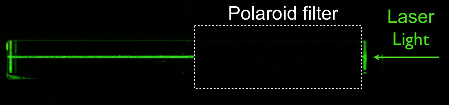
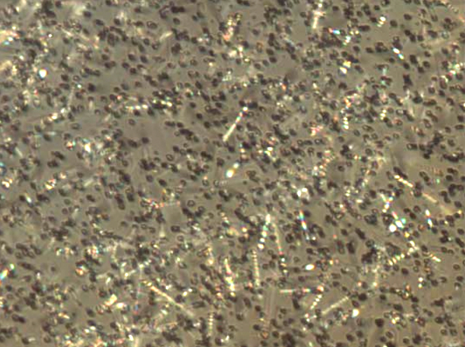
The features of hadron-induced changes in Light Transmission published in [1] are the peculiar ones of Rayleigh scattering, which implies the presence of dipole-shaped regions acting as scatterers for the light. When green 543.5 nm LASER light is shone through a hadron-irradiated crystal, as exemplified in the photograph of Fig. 1, its light gets scattered, making the beam visible. In the same photograph, a Polaroid filter was introduced between the observer and the crystal, as indicated by the dashed rectangle, so as to cover the right half of the crystal: the scattered LASER light is not transmitted by the filter. This demonstrates how the scattered light is polarized, yet another feature that is distinctive for Rayleigh scattering, and thus for the presence of localized regions of damage acting as scatterers for the light. All these observations were also observed at different wavelengths, as verified with 633 nm LASER light.
3 Microscopy observations - the method
While the macroscopic observations in Section 2 reveal the presence of scatterers, these are not individually visible to the naked eye. It was thus interesting to pursue a microscopy visualization, following the fission track analysis method used in geochronology for mineral dating [13]. The method is commonly used on minerals containing Uranium, which naturally exhibit damage tracks caused by the daughter products from spontaneous fission of . Geochronological mineral dating relies on the count of these fission tracks, but it also needs a complementary information: the Uranium concentration at a given time. Based on the abundance ratio, the Uranium concentration can be determined by inducing fission in the studied mineral through thermal neutron irradiation, with an external detector, such as high-purity muscovite mica, held in intimate contact with a polished section of the mineral surface. The fission fragments create induced tracks that reach the overlying external detector, where they are later revealed by chemical etching to make them easily visible for counting under an optical microscope and thus infer the concentration. It was thus obvious to apply this well-established methodology to attempt revealing induced fission damage in Lead Tungstate.
4 The irradiation setup
We have performed hadron irradiations using a setup suitable for allowing the visualization of damage trails, using the 24 GeV/c proton beam at the IRRAD1 facility [14] located in the T7 beam line of the CERN PS accelerator.
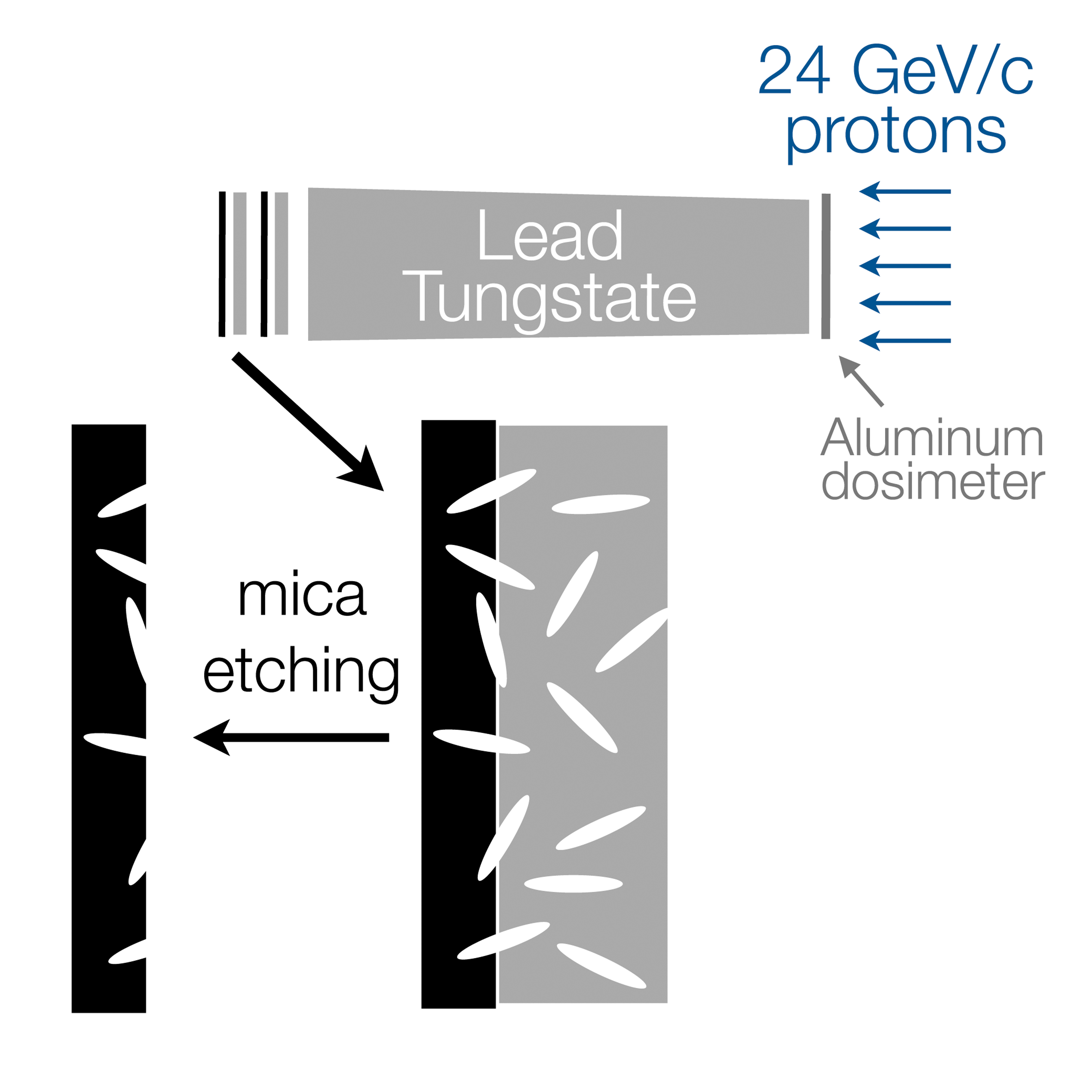
For each irradiation, two samples have been prepared, where a Lead Tungstate slide, 2 mm thick and 1 cm 2 cm in cross section, has been placed in intimate contact with a high-purity muscovite mica () slide of same cross section, 0.1 mm thick. The contact was ensured by a heat-shrinkable plastic wrapping. The samples have been placed behind a 7.5 cm long Lead Tungstate crystal for the irradiation, to make sure the running conditions are reproduced, that are encountered in homogeneous high-energy physics calorimetry, where energetic hadrons cause penetrating hadron showers, i.e. a cascade of nuclear interactions which are at the origin of the observed hadron-specific damage. The schematics of the irradiation setup is visible in Fig. 2. For the hadron irradiation, the proton beam was broadened to cover the whole crystal cross section, and the fluence for each irradiation was determined following the method described in [1], from the activation of a high-purity aluminum foil covering the crystal front face.
Three irradiations were performed, on different pairs of samples, up to fluences of, respectively, , and .
5 Visualization of damage tracks in mica
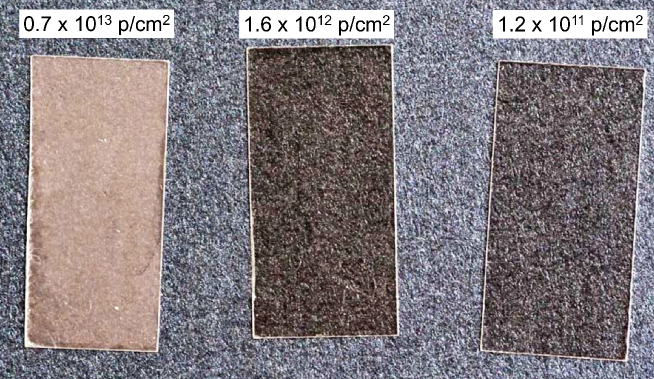
Fission damage in mica changes its crystalline structure into a metamict state, that is easily etched according to a well-known recipe [15], whereby the slides are immersed in HF at 40% for 45 min at C. The procedure allows to remove the material of the damaged region, leaving the surrounding crystalline matter intact. Examining by eye the mica slides after chemical etching (Fig. 3), one notices a coloration that intuitively correlates with the applied irradiation fluence.
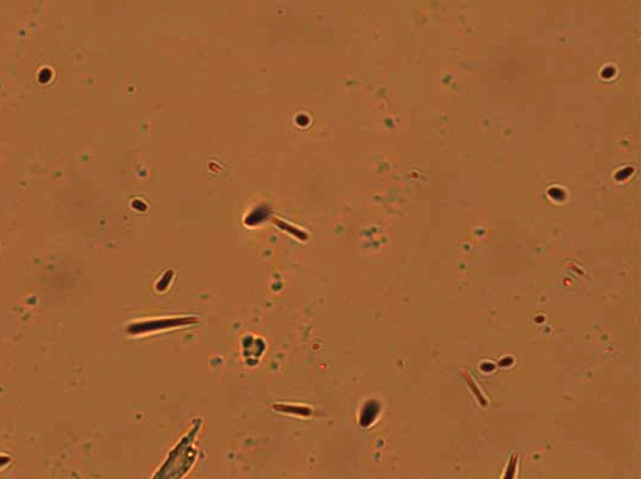
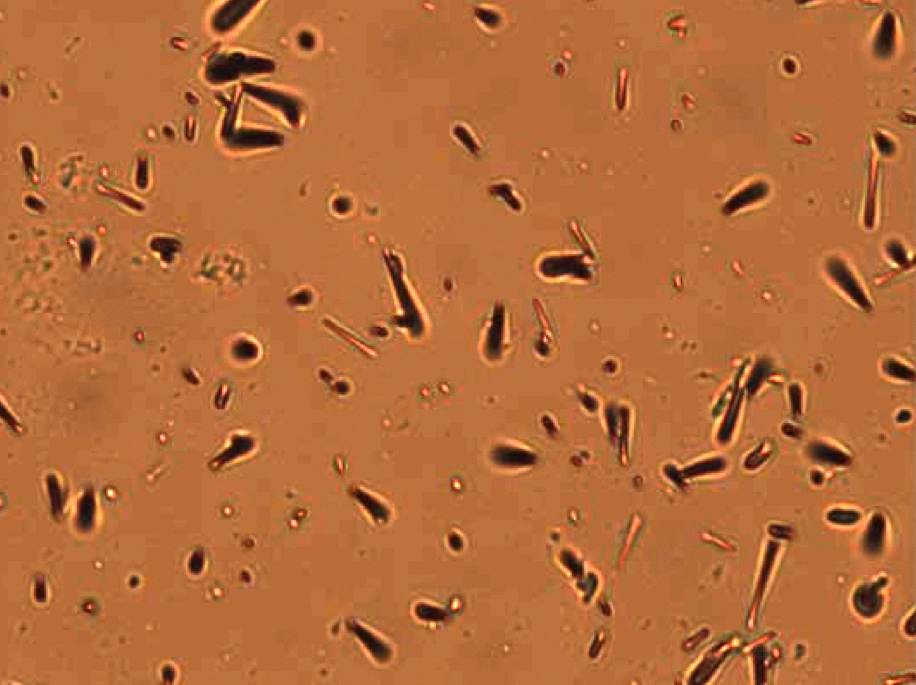
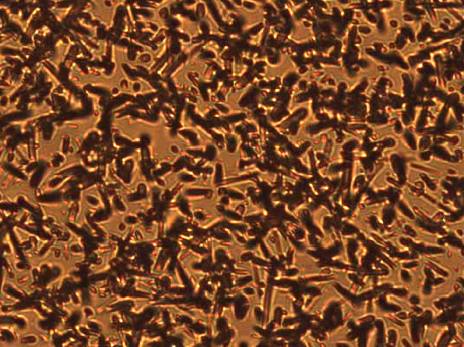
The mica slides were then examined with an Axio Imager Z1M optical microscope from Zeiss [16]. Transmitted light images are shown in Fig. 4. Linear damage tracks are visible, and they were counted at 1000x magnification but at the highest fluence, where individual tracks couldn’t be visually resolved. Their surface densities clearly correlate with the irradiation fluences, as listed in Table 1. Even where, for the highest fluence, no accurate count was possible, the proportionality is visually striking.
It can be qualitatively observed how the damage tracks are straight and occur in random orientations, as expected due to fission fragments produced by interactions in a hadron shower, and that they do not follow any pre-existing fabric in the mica.
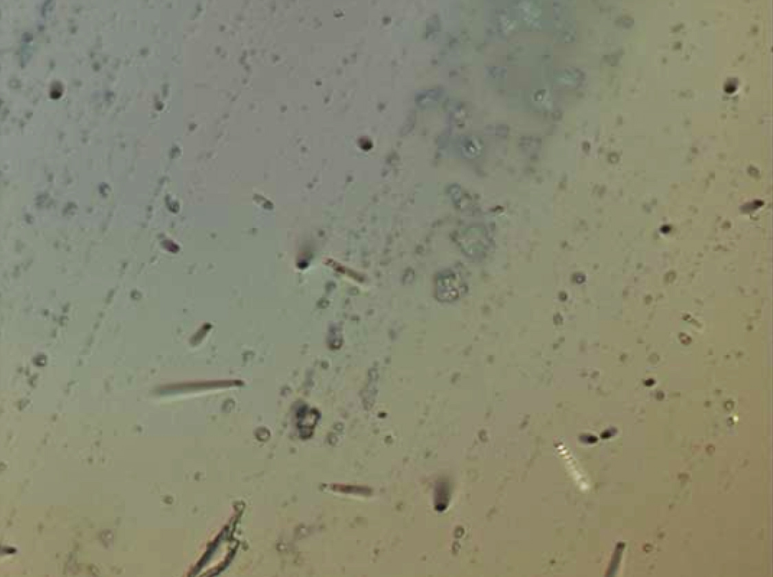
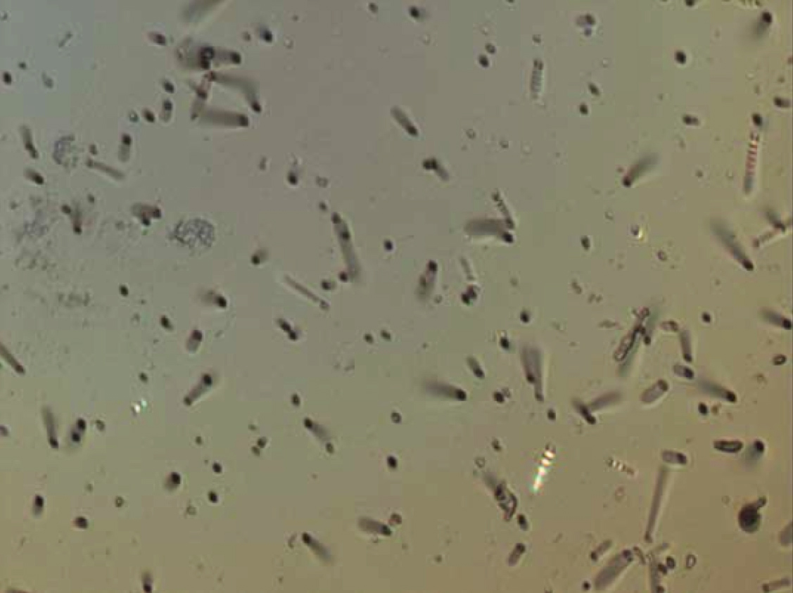
Additional information can be obtained from a comparison of images obtained in transmitted (Fig. 4) and reflected (Fig. 5) light. The two sets of images give consistent pictures. In particular, no etched, confined tracks are visible, as one would observe, if present, through the occasional intersection with surface tracks. Further, no tracks penetrate through the mica, as revealed by etch pits being present at all track terminations: the source of the tracks is external to the mica. From all these observations, the origin is clearly established to lie in the projection of break-up fragments from nuclei in the Lead Tungstate that underwent fission.
| p fluence | track density | Ratio |
|---|---|---|
| [cm-2] | [cm-2] | [] |
| not counted | - |
 |
 |
 |
 |
 |
 |
6 Complementary tests on Lead Tungstate
The methods developed in geochronology, to use mica as an external detector, allowed us to avoid having to etch the activated Lead Tungstate slides. An observation of those slides was however attempted, without a surface treatment, in a Sigma scanning electron microscope from Zeiss [16] equipped with a HKL Advance electron backscattered diffraction system from Oxford Instruments [17]. For each surface element hit by the electron beam during the scanning, an electron diffraction pattern is obtained and the local crystallographic orientation calculated from it. The quality of the pattern is influenced by a number of factors including local crystalline perfection, to account for it a quality value according to the contrast and sharpness of the diffraction pattern is also attributed to each surface element. Orientation maps and quality value maps provide a useful visualization of regions with different lattice orientation and with disturbed lattice structure respectively but is limited by the lateral resolution of the technique estimated to be of 200 nm (size of the smallest distinguishable details obtained in a scratched sample of the same material using the same analysis conditions). In order to avoid any artefact resulting from lapping and polishing micro scratches, cleaved faces obtained by breaking irradiated and not-irradiated slides were examined. As expected from a single crystal free of lattice damage, the orientation and quality value in the non-irradiated sample were homogeneous throughout the mapped region. The same results were obtained from the irradiated sample. This is not a surprise: typical fission track dimensions are small compared with the resolution of the technique.
All of these features are compatible with the observation of Rayleigh scattering in Lead Tungstate and of tracks due to fission fragments in mica, in that
It was in fact noticed e.g., by D. L. Mills that Rayleigh-type light scattering can occur simply due to the damage regions having “optical boundaries” from mechanical strains after re-crystallization, : “…the inclusion of scattering from the strain halo …leaves the well-known dependence unaltered” [20].
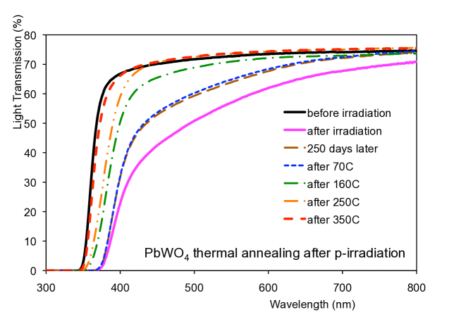
It might be interesting to note that the scattering centers can be eliminated by heating the crystals up to 350 oC [1], and that such a heating treatment is also used after ingot production to anneal mechanical stresses before cutting and polishing [21]. The progressive recovery of crystal light transmission through heating up to different temperatures is visible in Fig. 6, where transmission curves are shown after the crystal was subjected to various heating cycles performed in an increasing temperature order. The crystal, labelled “d” in [1], was annealed 240 days after irradiation. The annealing temperature was reached in a programmable oven, by increasing the temperature linearly over 2 hours. The crystal was then kept at the target annealing temperature for 8 hours. The temperature of the oven was then reduced to room temperature over two hours. While essentially no recovery of the crystal was observed at 160 oC, partial recovery took place at 250 oC. At a temperature of 350 oC almost complete recovery was reached, except for a small residual shift of the band-edge. Shining LASER light through the crystal after the damage annealing by heating, no scattering centers are observed.
Conclusions
Macroscopic observations show that light scattering centers are left in Lead Tungstate after hadron irradiation, which are permanent at room temperature, as described in our earlier work [1]. The work presented here has allowed to visualize this damage at a microscopic scale, as damage tracks originating in Lead Tungstate and entering mica slides used as an external detector. Scanning Electron Microscope imaging tests indicate the damage regions in Lead Tungstate are in average crystalline but for - possibly - a track core, that is not visible due to the finite spacial resolution of the technique. It is understood that Rayleigh-type light scattering can occur, due to the damaged regions having “optical boundaries” from mechanical strains remaining after re-crystallization.
The microscopic observations presented in this work confirm our understanding of the damage mechanism due to hadrons in Lead Tungstate, where the fragments from the fission induced in Lead and Tungsten cause severe, local damage to the crystalline lattice due to their extremely high energy loss over a short track. This evidence is relevant, in that it confirms our understanding of the damage mechanisms involved.
This confirmed understanding will have to be taken into account when selecting materials for high-energy physics calorimeters, where an exposure to large integrated fluences of energetic hadrons is expected. Specifically, we have confirmed that scintillators should be avoided, that are composed by elements with a Z 71, which is the threshold [5] at which fission becomes important.
Acknowledgements
We are indebted to the CERN PS accelerator team, that provided us with the required beam conditions for the proton irradiations. We are deeply grateful to M. Glaser, who operated the proton irradiation facility and provided the Aluminium foil dosimetry.
References
- [1] M. Huhtinen, P. Lecomte, D. Luckey, F. Nessi-Tedaldi, F. Pauss, Nucl. Instr. and Meth. A 545 (2005) 63-87.
- [2] P. Lecomte, D. Luckey, F. Nessi-Tedaldi, F. Pauss, D. Renker, Nucl. Instr. and Meth. A 587 (2008) 266 - 271.
- [3] P. Lecomte, D. Luckey, F. Nessi-Tedaldi, F. Pauss, Nucl. Instr. and Meth. A 564 (2006) 164-168.
- [4] F. Nessi-Tedaldi, “Studies of the effect of charged hadrons on Lead Tungstate crystals”, J. Physics: Conf. Series 160 (2009) 012013.
- [5] A.S.Iljinov, M. V. Mebel, C. Guaraldo, V. Lucherini, E. De Sanctis, N. Bianchi, P. Levi Sandri, V. Muccifora, E. Polli, A. R. Reolon, and P. Rossi, S. Lo Nigro, Phys. Rev. C 39 (1989) 1420-1424.
- [6] G. Dissertori, P. Lecomte, D. Luckey, F. Nessi-Tedaldi, F. Pauss, Th. Otto, S. Roesler, Ch. Urscheler, Nucl. Instr. and Meth. A 622 (2010) 41-48.
- [7] M. Kobayashi et al., Nucl. Instr. Meth. 206 (1983) 107-117.
- [8] F. Nessi-Tedaldi, Int. J. Mod. Phys. A20 (2005) 3826-3829.
- [9] M. Korjik, to be published in Proc. “SCINT 2011, 11th International Conference on Inorganic Scintillators and their Applications” (Giessen, Germany, 2011).
- [10] F. Dessauer, Zeit. Physik 12 (1923) 38.
- [11] L. T. Chadderton, I. McC. Torrens, ”Fission damage in crystals”, Methuen & Co. Ed., London (1969);
- [12] P. D. Townsend, P. J. .Chandler, L. Zhang, “Optical Effects of Ion Implantation”, Cambridge Univ. Press, Cambridge (1994).
- [13] B. P. Price and R. M. Walker, J. Geophys. Res. 68 (1963) 4847-4862; R. L. Fleischer, B. P. Price and R. M. Walker, ibidem 69 (1964) 4885.
- [14] ROSE/RD48 Collaboration, M. Glaser, L. Durieu, F. Lemeilleur, M. Tavlet, C. Leroy, P. Roy, Nucl. Instr. and Meth. A 426 (1999) 72.
- [15] R. L. Fleischer, B. P. Price and R. M. Walker, “Nuclear Tracks in Solids: Principles and Applications”, University of California Press (Berkeley, USA, 1975) and references therein.
- [16] Carl Zeiss AG, 8714 Feldbach (Switzerland) and http://www.zeiss.com
- [17] Oxford Instruments, Abingdon, Oxfordshire, United Kingdom and http://www.oxinst.com
- [18] N. Tomašić, A. Gajović, V. Bermanec, D. S. Su, M. Rajić-Linarić, T. Ntaflos, R.Schlögl, Phys. Chem. Minerals 33 (2006) 145-159
- [19] P. Tolédano, U. Bismayer, J. Phys.: Condens. Matter 17 (2005) 6627-6634.
- [20] D. L. Mills, J. Appl. Phys. 51 (1980) 5864.
- [21] A. Annenkov, E. Auffray, G. Drobychev, M. Korzhik, V. Kostyleva, O. Kovalev, P. Lecoq, V. Ligoun, O. Missevitch, R. Zouevski, Nucl. Instr. and Meth A 537 (2005) 173-176.