Energetics of hydrogen/lithium complexes in silicon analyzed using the Maxwell construction
Abstract
We have studied hydrogen/lithium complexes in crystalline silicon using density-functional-theory methods and the ab initio random structure searching (AIRSS) method for predicting structures. A method based on the Maxwell construction and convex hull diagrams is introduced which gives a graphical representation of the relative stabilities of point defects in a crystal and enables visualization of the changes in stability when the chemical potentials are altered. We have used this approach to study lithium and hydrogen impurities in silicon, which models aspects of the anode material in the recently-suggested lithium-ion batteries. We show that hydrogen may play a role in these anodes, finding that hydrogen atoms bind to three-atom lithium clusters in silicon, forming stable {H,3Li} and {2H,3Li} complexes, while the {H,2Li} complex is almost stable.
pacs:
61.05.-a, 61.72.J-, 82.47.AaI Introduction
The properties of a material may be substantially affected by the presence of impurity atoms.stoneham:OUP:1975 One of the fundamental properties is the relative energies of different configurations of the impurities within the material. Several different species of atom may be present, and the impurity atoms may have strong interactions with each other and with the host material. In this paper we study the interactions between lithium and hydrogen impurities in crystalline silicon, which is a system of interest for lithium-ion battery technologies. Lithium-ion batteries are widely used in portable electronics and are now being employed in the next generation of hybrid and all-electric vehicles. LIB_background Recently there has been interest in using silicon anodes, which have a very high volumetric and gravimetric capacity. lai:JES:1976 ; wen:JSSC:1981 ; weydanz:JPS:1999 Crystalline silicon is generally used in the battery and the first charge-discharge cycle involves the conversion of crystalline silicon to an amorphous phase.
Point defects may form a variety of complexes containing several atoms of more than one atomic species. An interesting feature of our approach is the use of a graphical representation of the relative stabilities of the defects based on the Maxwell constructiongibbs_1873 ; maxwell_1874 and the corresponding convex hull. This is a standard procedure used in materials science (and elsewhere) for studying phase separation, which we have applied to defects in crystals. The term “convex hull” refers to the fact that the second law of thermodynamics requires that the energy per particle (or free energy as appropriate) must be a convex function of the relative concentrations of the particles. Appropriate chemical potentials for the different atomic species can normally be estimated for a particular set of external conditions. We are also interested in the changes in the relative stabilities of defects when the chemical potentials of the atomic species are altered. Charged defects are also of interest in general, and these can be included by introducing a chemical potential for electrons, although we will not show results for this case here.
This article is divided into the following sections, in Sect. II, the modified Maxwell construction is introduced to visualize the energetics of the phase separation of defect complexes, and the example of N/O complexes in silicon is used to validate the method. In Sect. III the method is applied to the problem of H/Li defect complexes in silicon. Finally Sect. IV concludes the work.
II Convex Hull for defects
In this article we denote a defect complex by listing its constituent atoms between braces, for example, the {2H,3Li} defect complex contains two hydrogen and three lithium atoms. For simplicity we begin by considering a single impurity species which forms a single impurity complex in a large sample of perfect bulk crystal. The formation energy of a complex {} containing impurity atoms is given by
| (1) |
where is the energy of the system including the defect complex, is the chemical potential of the impurity species, and is the energy of the host crystal without defects. The energy of the host crystal can be written as
| (2) |
where there are atoms of the host crystal atoms of each species which have chemical potentials . The complex with the lowest value of is the most stable and ones with higher energies are metastable.
Eq. (1) can readily be extended to a complex containing a larger number of impurity species, and the formation energy per impurity atom is then
| (3) |
The convex hull diagram is constructed by plotting the formation energy per impurity atom of each complex against the fractional concentration of impurity species , where
| (4) |
If the complexes contain only two atomic species we can simply plot on a graph as shown, for example, in Fig. 1. The solid red and blue lines in Fig. 1 show convex hulls which consist of straight-line segments known as “tie lines”. A higher-dimensional hull is required if there are more than two impurity species. The case of three atomic species can be represented on a “triangular plot” as shown, for example, in Ref. ong:cm:2008, . Alternatively one can consider two-dimensional slices of the multi-dimensional hull. Electrons can also be included as a species, so that defect complexes in different charge states can be described.
When more than one impurity species is present it is possible for “phase separation” or “disproportionation” of defect complexes to occur. For example, the lowest energy state when equal numbers of impurity species A and B are present might consist of equal numbers of the defect complexes {A,2B} and {A}, rather than the defect complex {2A,2B}. We will assume that the defect complexes do not interact with one another (except by a “chemical reaction”, forming new complexes which can be included within the theory) and they are expected to be distributed randomly over the host crystal rather than forming spatially distinct phases as in the standard application to “phase separation”. We may include within the contributions to the free energy from the vibrational entropy and the configurational entropy due to the different degenerate orientations of a complex at a lattice site. However, it is not possible to include the configurational entropy due to arranging defects at different lattice sites within , since it depends on the concentrations of the impurity complexes. Hence the Maxwell construction is exact only at zero temperature, and a full statistical mechanical description is required at finite temperatures. The standard plot of the defect formation energy against the chemical potential found in the defect literature (see, for example, Fig. 2 of Ref. Zhang:PRL:1991, ), suffers from the same limitation.
II.1 Application to N/O complexes in silicon
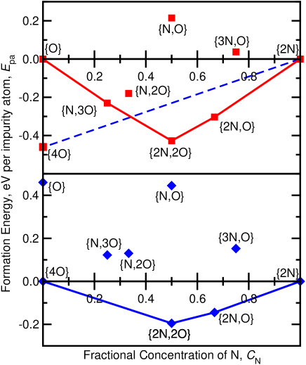
We use N/O complexes in silicon to illustrate our approach and outline the advantages of the method. Fig. 1 shows a convex hull containing N/O complexes from a previous study. morris:PRB:2009 The hull shown in the upper panel of Fig. 1 is constructed as follows. We choose the chemical potentials for the N and O atoms to be the same as in our previous study.morris:PRB:2009 The chemical potential for N is obtained from the energy of the {2N} defect as
| (5) |
while for O it is obtained from the energy of the {O} defect as
| (6) |
These energies are plotted on the diagram at the points (=0,=0) and (0,1). The solid-red convex hull is then drawn as a series of straight-line segments between (0,0) and (0,1) passing through the squares representing the energies per impurity atom in such a way that none of the defects lie below the hull. Only the complexes which lie on the hull are stable. The {O}, {N,3O}, {N,2O}, {2N,2O} and {2N,O} defects are all stable since they lie on the tie line of the convex hull, but the {N,2O} complex is not stable and the energy would be lowered if these defects disproportionated such that
| (7) |
The dashed blue line in the upper panel of Fig. 1 indicates how the situation would be modified if the chemical potential for O is changed to the energy of the much more stable {4O} complex. The modified complex hull is redrawn as the solid-blue line in the lower panel of Fig. 1. It is clear from either the upper or lower panels that the {N,3O} defect is no longer stable under these circumstances and the energy would be lowered if they disproportionated such that
| (8) |
These results are entirely consistent with the analysis reported in Ref. morris:PRB:2009, . The graphical representation is useful because it shows which defects are stable for a particular choice of chemical potentials, and it also allows an easy visualization of the effects of altering the chemical potentials. The convex hull also shows the amount by which the energy is lowered by the disproportionation of defect complexes.
II.2 Native defects
Our approach is easily extended to account for a crystal containing native vacancies which form complexes {,,} or interstitials forming complexes {,,}. The native defects may be included within this framework, not as new “impurities species”, but as a change in the definition of the host material. The chemical potential of an atom of the host material added at a surface of the crystal is equal to the cohesive energy of an atom in the perfect bulk crystal since and, as long as the surface is large, the surface energy is unchanged by adding an atom at a “kink site” on a surface terrace. Hence in the case where the vacancy is absent prior to the addition of impurities, is the chemical potential of each host species in the perfect crystal. If the vacancy is present prior to the addition of impurities, is the chemical potential of host species in a crystal containing the vacancy. Note that it is not possible to describe more than one type of vacancy in this approach unless each type is treated as a separate species. The same applies for interstitials.
III Study of H/Li complexes in silicon
III.1 H and Li in silicon
Hydrogen is a common impurity in silicon which binds to a variety of defect complexes, including those containing oxygen and nitrogen.morris:PRB:2009 It is difficult to determine the concentration of hydrogen in silicon samples although it is likely to be present at virtually every stage of manufacture and it may be incorporated at levels of up to about cm-1.amv:1992 The role of hydrogen impurities in semiconductors has been reviewed by Estreicher.estreicher:MSE:1995 In this article we present results for H/Li impurities in bulk silicon. Both amorphouschevrier:JES:2009 ; chevrier:JES:2010 and crystallinechevrier:JAC:2010 phases of the Li-Si system have been studied using density-functional-theory (DFT) methods, giving voltages which agree with experiment to within 0.1 V. Wan et al.wan:JPC:2010 studied lithium defects in silicon using DFT and found the most stable position for a single lithium impurity to be at the tetrahedral () site, which is preferred to substitution on a silicon site. Kim et al.kim:JPCC:2010 performed a detailed study of the electronic structure of a lithium atom in bulk silicon, concluding that the presence of lithium weakens the nearby Si–Si bonds.
III.2 DFT calculations
We have predicted structures of lithium impurities in silicon using DFT and the ab initio random structure searching method (AIRSS).pickard:PRL:2006:silane ; pickard:JPC:airss_review In this method randomly generated structures are relaxed to a minimum in the energy. This approach has been successful in predicting the structures of point defects in semiconductorsmorris:PRB:2008 ; morris:PRB:2009 and ceramics,mulroue:PRB:2011 as well as high-pressure phases of materials such as solid silane,pickard:PRL:2006:silane hydrogen,pickard:NP:2007:hydrogen and lithium.pickard:PRL:2009:lithium Each AIRSS run was performed at a fixed stoichiometry. Searches were performed at several stoichiometries and the results were analyzed using the convex hull construction.
We used simulation cells containing 1, 2, 3 or 4 lithium atoms, 1, 2, 3 or 4 lithium atoms plus 1 hydrogen, atom and 1, 2 or 3 lithium plus 2 hydrogen atoms. The initial structures were chosen in a similar fashion to those in our earlier study of H/N/O defects.morris:PRB:2009 A small hole was made in the host crystal by removing a silicon atom from the unit cell and placing the appropriate number of lithium atoms and a silicon atom randomly within the hole. The configurations were then relaxed using the DFT forces. Some of the starting configurations relaxed to structure in which two or more separate defects were present, and these structures were discarded.
The plane-wave basis-set DFT code castepCASTEP:ZK:2004 was used to calculate ground-state total energies and optimize the geometries of the candidate structures. We used “on-the-fly” ultrasoft pseudopotentialsVanderbilt:PRB:1990 and the PBEperdew:PRL:1996 parameterization of the generalized gradient approximation to the exchange-correlation functional. The initial searches were performed with simulation cells containing 32 silicon atoms plus impurity atoms, sampling the Brillouin zone using the multi-k-point generalizationRajagopal:PRL:1994 ; Rajagopal:PRB:1995 ; morris:PRB:2008 of the Baldereschi scheme.Baldereschi:PRB:1973 The basis set contained all plane-waves with energies up to 300 eV.
The lowest-energy structures from each search were then further relaxed at a higher level of accuracy. We used simulation cells containing 256 silicon atoms and a basis set with plane-waves up to 500 eV, a harder Li pseudopotential and a standard Monkhorst-Pack grid of k-points. The formation energies were then calculated using these structures but with a larger Monkhorst-Pack grid of k-points. We also performed some calculations in which we allowed spin polarization to occur, but no significant effects were found.
III.3 Results for H/Li in silicon
| Defect | (eV) |
|---|---|
| {3Li} | 0.422 |
| {H,3Li}∗ | 0.103 |
| {H,3Li} | -0.139 |
| {H,2Li}∗∗ | 0.321 |
| {H,2Li}∗ | 0.301 |
| {H,2Li} | 0.101 |
| {2H,3Li}∗∗ | 0.114 |
| {2H,3Li}∗ | -0.010 |
| {2H,3Li} | -0.239 |
| {H,Li}∗∗ | 0.474 |
| {H,Li}∗ | 0.472 |
| {H,Li} | 0.401 |
| {2H,2Li} | -0.028 |
| {2H,Li}∗ | 0.413 |
| {2H,Li} | -0.076 |
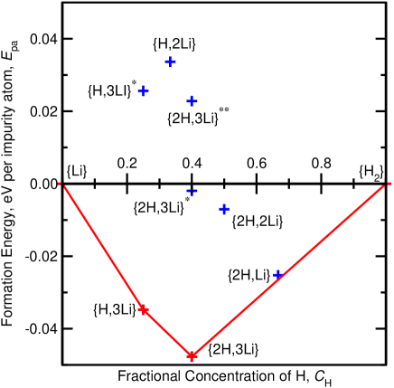
We model the initial stages of the incorporation of Li atoms into bulk silicon as the formation of defect complexes with varying concentrations of H and Li atoms. We assume that the Li atoms are supplied from bulk body-centered-cubic Li metal. The {Li} defect in silicon has a formation energy of 0.21 eV relative to bulk Li in accordance with the observed overpotential during Li insertion reactions in bulk silicon. obrovac:JES:2007 We assume that the Li atoms initially form {Li} defects in the bulk silicon and we investigate whether chemical reactions between Li and H atoms in bulk silicon are energetically favorable. We choose the {Li} defect to define our chemical potential because it is the lowest energy defect that we have found in silicon and because a lithium defect of the same () symmetry has been observed in electron paramagnetic resonance experiments in bulk silicon.watkins:PRB:1970 A metastable {3Li} complex with symmetry was also found with formation energy relative to {Li} of 0.14 eV per atom, but this is too high in energy to appear on Fig. 2. The hydrogen chemical potential was obtained as in previous studiesmorris:PRB:2008 ; morris:PRB:2009 from a H2 molecule at the site in silicon. A more complete model would require the inclusion of other defects, such as vacancies and vacancy complexes.
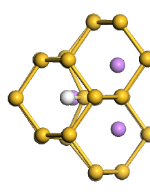
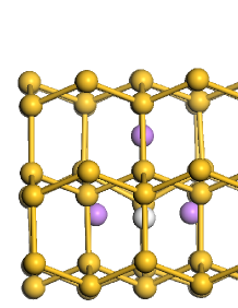
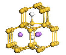
Single-atom Li defects are favored when only Li impurities are present, but the convex hull plotted in Fig. 2 shows that the addition of hydrogen causes the lithium atoms to cluster. For the {H,3Li} defect forms and any additional lithium atoms occupy sites. The structure of the {H,3Li} defect is pictured in Fig. 3. Both the {H,3Li} and {2H,3Li} complexes are present in the range . The {2H,3Li} defect is present when , and any excess hydrogen forms H2 molecules at the site. The {H,3Li}, {2H,3Li} and {2H,Li} defects resemble a Chadi H defectchadi:APL:2003 with the lithium atoms close by. The metastable H complex found by Chadichadi:APL:2003 has a formation energy relative to a H2 molecule at the site of 0.1 eV per H atom.morris:PRB:2008 The {2H,Li} defect could be present when thermal effects are taken into account, due to its close proximity to the tie line at .
IV Conclusions
We have used convex hull diagrams based on the Maxwell construction to visualize the energetics of defect complexes. The graphical representation shows the stable defects for a particular choice of chemical potentials and the relative stabilities of the defect complexes. It allows visualization of the changes in the stability of the defects when the chemical potentials are changed. The approach was illustrated using data for N/O complexes in silicon from a previous study.morris:PRB:2009 The method can easily be extended to crystals containing charged species, native vacancies or interstitials, which is an area we are currently investigating.
We also studied H/Li complexes in silicon, which may be relevant to understanding how the first few Li atoms enter crystalline silicon. This extended the previous analysis of lithium in silicon anodes to include its interaction with the hydrogen that is introduced into the silicon during manufacture. When only lithium impurity atoms are present the most stable defect is {Li}, but the presence of hydrogen atoms causes the lithium atoms to form H/Li clusters containing three lithium atoms. We found that the {H,3Li} and {2H,3Li} complexes are stable and that the {2H,Li} complex is nearly stable. Hydrogen present in the bulk favors bonding covalently to self-interstitial defects,morris:PRB:2008 but once the silicon defects are saturated, hydrogen will bind to lithium complexes, further stabilizing them. The combination of AIRSS and the Maxwell construction and convex hull diagrams is a powerful tool for analyzing the energetics of point defects in materials.
Acknowledgements.
We are grateful to Marshall Stoneham, Tony Harker, Dave Bowler and Mike Gillan for fruitful discussions. This work was supported by the Engineering and Physical Sciences Research Council (EPSRC) of the U.K. Computational resources were provided by the University College London Research Computing service.References
- (1) A. M. Stoneham, Theory of Defects in Solids: Electronic structure of defects in insulators and semiconductors (Oxford University Press, Oxford, 1975).
- (2) J. M. Tarascon and M. Armand, Nature 414, 359, (2001).
- (3) S. Lai, J. Electrochem. Soc. 123, 1196 (1976).
- (4) C. J. Wen and R. A. Huggins, J. Sol. Stat. Chem. 37, 271 (1981).
- (5) W. J. Weydanz, M. Wohlfahrt-Mehrens and R. A. Huggins, J. Power Sources 81-82, 237 (1999).
- (6) J. W. Gibbs, Graphical Methods in the Thermodynamics of Fluids, Part 1 pp. 309-342, A Method of Geometrical Representation of the Thermodynamic Properties of Substances by Means of Surfaces, Part 2 pp. 382-404, Transactions of the Connecticut Academy of Arts and Sciences Vol. II, 1873.
- (7) J. C. Maxwell, Theory of Heat, Longmans, Green and Co, pp. 195-208 (1904) and Scientific Letters and Papers of J.C. Maxwell, Vol. 3, 1874-1879, Edited by P.M. Harman, (Cambridge University Press, Cambridge, 2002).
- (8) S. P. Ong, L. Wang, B. Kang, and G. Ceder, Chem. Mater. 20, 1798 (2008).
- (9) S. B. Zhang and J. E. Northrup, Phys. Rev. Lett. 67, 2339 (1991).
- (10) A. J. Morris, C. J. Pickard, and R. J. Needs, Phys. Rev. B 80, 144112 (2009).
- (11) S. Pearton, M. Stavola, and J. W. Corbett, Advanced Materials 4, 332 (1992).
- (12) S. K. Estreicher, Mater. Sci. Eng. B 14, 319 (1995).
- (13) V. L. Chevrier and J. R. Dahn, J. Electrochem. Soc. 156, A454 (2009).
- (14) V. L. Chevrier and J. R. Dahn, J. Electrochem. Soc. 157, A392 (2010).
- (15) V. L. Chevrier, J. Zwanziger, and J. R. Dahn, J. Alloys Compd. 496, 25 (2010).
- (16) W. Wan, Q. Zhang, Y. Cui, and E. Wang, J. Phys.: Condens. Matter 22, 415501 (2010).
- (17) H. Kim, K. E. Kweon, C.-Y. Chou, J. G. Ekerdt, and G. S. Hwang, J. Phys. Chem. C 114, 17942 (2010).
- (18) C. J. Pickard and R. J. Needs, Phys. Rev. Lett. 97, 045504 (2006).
- (19) C. J. Pickard and R. J. Needs, J. Phys.: Condens. Matter 23, 053201 (2011).
- (20) A. J. Morris, C. J. Pickard, and R. J. Needs, Phys. Rev. B 78, 184102 (2008).
- (21) J. Mulroue, A. J. Morris, and D. M. Duffy, Phys. Rev. B 84, 094118 (2011).
- (22) C. J. Pickard and R. J. Needs, Nature Phys. 3, 473 (2007).
- (23) C. J. Pickard and R. J. Needs, Phys. Rev. Lett. 102, 146401 (2009).
- (24) S. J. Clark et al., Z. Kristallogr. 220, 567 (2005).
- (25) D. Vanderbilt, Phys. Rev. B 41, 7892 (1990).
- (26) J. P. Perdew, K. Burke, and M. Ernzerhof, Phys. Rev. Lett. 77, 3865 (1996).
- (27) G. Rajagopal, R. J. Needs, S. Kenny, W. M. C. Foulkes, and A. James, Phys. Rev. Lett. 73, 1959 (1994).
- (28) G. Rajagopal, R. J. Needs, A. James, S. D. Kenny, and W. M. C. Foulkes, Phys. Rev. B 51, 10591 (1995).
- (29) A. Baldereschi, Phys. Rev. B 7, 5212 (1973).
- (30) G. D. Watkins and F. S. Ham, Phys. Rev. B 1, 4071 (1970).
- (31) D. J. Chadi, Appl. Phys. Lett. 83, 3710 (2003).
- (32) M. N. Obrovac and L. J. Krause, J. Electrochem. Soc. 154 A103 (2007).