Ubiquity of optical activity in planar metamaterial scatterers
Abstract
Recently it was discovered that periodic lattices of metamaterial scatterers show optical activity, even if the scatterers or lattice show no 2D or 3D chirality, if the illumination breaks symmetry. In this Letter we demonstrate that such ‘pseudo-chirality’ is intrinsic to any single planar metamaterial scatterer and in fact has a well-defined value at a universal bound. We argue that in any circuit model, a nonzero electric and magnetic polarizability derived from a single resonance automatically imply strong bianisotropy, i.e., magneto-electric cross polarizability at the universal bound set by energy conservation. We confirm our claim by extracting polarizability tensors and cross sections for handed excitation from transmission measurements on near-infrared split ring arrays, and electrodynamic simulations for diverse metamaterial scatterers.
Many historical debates on how to describe the effective electrodynamic response of media composed of subwavelength building blocks currently acquire new relevance in nano-optics. Initiated by the works of Veselago and Pendry Veselago68 ; Pendry00 , efforts are focused on manipulating effective medium parameters in nanostructured media. On the one hand, the drive for arbitrary and is generated by the idea that light fields can be arbitrarily reshaped by conformal transformations, provided we can create arbitrary constitutive tensors Pendry06 ; Leonhardt06 ; Schurig06 . On the other hand, a convergence with plasmonics has led to the realization that subwavelength scatterers mimic and even greatly enhance rich scattering phenomena known from molecular matter. For example, resonantly induced optical magnetism in 2D and 3D chiral metal nano-objects results in giant circular birefringence, optical rotatory power, broadband optical activity, and circular dichroism in frequency ranges from microwave, mid-IR, near IR to even visible frequencies Valev09 ; Gorodetsky09 ; Gansel09 ; Drezet08 ; Zhang09 ; Decker10 ; Li10 ; Zhou09 ; Plum09 . The fact that strong optical activity is easily attained using chiral subwavelength scatterers is promising for many applications such as broadband optical components, as well as providing excellent candidates for achieving negative refraction Pendry04 , or repulsive Casimir forces SoukoulisCasimir . Moreover, the promise of enhancing detection of molecular chirality via enhanced chirality in the excitation field, is expected to be of large importance for, e.g., discrimination of enantiomers in biology or medicine Govorov10 ; Hendry10 ; Cohen10 ; Cohen11 .
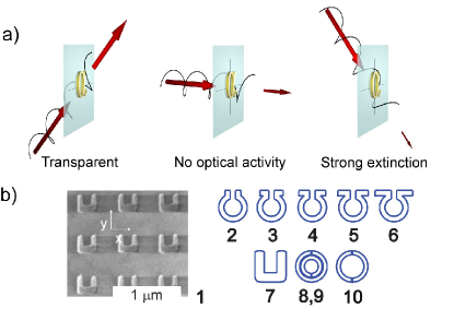
A question of essential importance is how to control the optical activity of a single building block, i.e., have independent control over the degree of magnetic response, electric response and magneto-electric cross coupling or ‘bianisotropy’ whereby incident electric (magnetic) fields cause a magnetic (electric) material polarization in a single building block SihvolaBook . For instance, in attempts to reach negative indices, researchers soon found that the archetypical split ring resonator (SRR) has a magneto-electric response that is undesirable, yet difficult to remove without also losing the magnetic response SoukoulisAPL . Completely opposite to the desire to remove this bianisotropy, it has also been realized that all applications exploiting optical activity benefit from strong magneto-electric coupling. Currently it is unclear if there exists any universal bound to which optical activity can be benchmarked, or conversely, if it is at all possible to avoid bianisotropy without also losing the magnetic response Sersic11a . In this Letter, we discuss precisely such a universal bound for magneto-electric coupling for single scatterers, disentangled from any lattice properties. We claim that Onsager’s relations constrain optical activity to always be at this maximum bound for any dipole scatterer based on planar circuit designs, independent of geometrical chirality. Our claim is supported by measurements on SRRs at telecom wavelengths and rigorous full wave calculations Kern09 in which we retrieve cross sections and polarizabilities for various metamaterial scatterers (see Fig. 1(a,b)).
The central quantity in this Letter is the polarizability tensor that quantifies the magnetic response, electric response and magneto-electric cross coupling (bianisotropy) intrinsic to a single metamaterial building block according to SihvolaBook ; Sersic11a :
| (1) |
For molecules, optical activity is due to weak cross coupling, i.e., a perturbative , while . In contrast, the paradigm of metamaterials is that a single scatterer acquires a magnetic dipole moment at least comparable to the electric moment , with , , and possibly of the same order, which all derive from a single resonance footnote .
In order to quantify the polarizability for the canonical SRR, we performed transmission measurements as well as full-wave calculations. For the experiments we fabricated Au SRRs arranged in square arrays on glass substrates by electron beam lithography (e-beam), resonant at telecom wavelengths Enkrich05 ; Sersic09 . Fig. 1(b) shows a scanning electron micrograph (SEM) of a SRR array with 530 nm lattice spacing, which is so dilute that coupling between SRRs is small Sersic09 , yet so dense that no grating diffraction occurs. Each SRR measures 23023030 nm, with a gap between the arms that is 100 nm wide and 145 nm deep. We record transmission by illuminating the sample with a narrow band of frequencies at a time, selected from a supercontinuum laser (Fianium), using an acousto-optical tunable filter (Crystal Technologies) with a bandwidth of 1-2 nm Sersic11b . The beam is chopped for lock-in detection on an InGaAs photodiode. We polarize the incident beam using a broadband quarter-wave plate, to provide circularly polarized excitation. We weakly focus the beam onto the sample (=100 mm). Light is collected with a low NA collection lens (=20 mm), and passed through a telescope and pinhole to ensure spatial selection from within a 200x200 m2 e-beam write field, as monitored by an InGaAs camera. A motorized rotation stage allows transmission measurements versus incident angle relative to the sample normal.
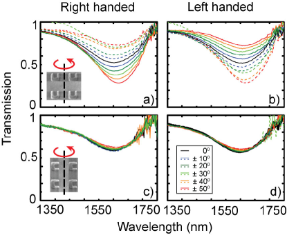
Fig. 2 shows transmission versus wavelength for left and right handed circularly polarized incident light, for incidence angles from -50∘ to +50∘. Fig. 2 (a) shows data when the angle is varied from normal incidence by rotating the SRRs around their mirror axis . At normal incidence, the magnetic LC resonance is evident around 1600 nm wavelength as a minimum in transmission. As opposed to the deep minima usually reported for linear, -polarized transmission ( along the gap) of dense arrays, the transmission dip is shallow since our lattice is dilute and the LC resonance is associated only with and , and completely transparent for . As the incidence angle is moved away from the normal, the excitation also offers as a driving field, a quarter wave out of phase with . A very clear asymmetry around the normal develops. For right-handed light the transmission minimum becomes continuously shallower towards negative angles, and the sample is nearly transparent for . In contrast, the transmission minimum significantly deepens from 28% to 75% when going to large positive angles. The asymmetric behavior with incidence angle is mirrored for opposite handedness (Fig. 2(b), consistent with oblique incidence optical activity. For linear polarization the transmission is symmetric around normal incidence (not shown).
The fact that optical activity is symmetry-allowed even for lattices containing 2D non-chiral objects aligned with the lattice symmetry, was already reported by Plum et al. Plum11 , who coined this ‘extrinsic 3D chirality’. In contrast to symmetry arguments that only distinguish between allowed and forbidden effects without quantifying the strength of optical activity, it is the express aim in this Letter to ascertain what the single element polarizability is that leads to the strong optical activity. We exclude the array structure factor as the cause of handed behavior Gompf11 , as the optical activity disappears when we rotate the SRRs by 90∘ in the sample plane (Fig. 2 (c) and (d)). We hence conclude that the single SRR polarizability must contain the strong ‘pseudo-chiralilty’ that is expressed as huge circular dichroism contrast in the extinction cross section, despite SRRs being neither 2D nor 3D chiral. Qualitatively, the description of a single SRR indeed contains optical activity under oblique incidence. Charge motion is set by , where is the inductance, the capacitance, the Ohmic resistance, the capacitor plate gap and the enclosed area. Full transparency despite the presence of suitable driving along the gap and through the split ring occurs when . Conversely, optimum driving of a SRR benefits from an opposite quarter wave phase difference between and so that has maximum magnitude. Circular polarization at oblique incidence provides the required quarter wave phase difference between and .
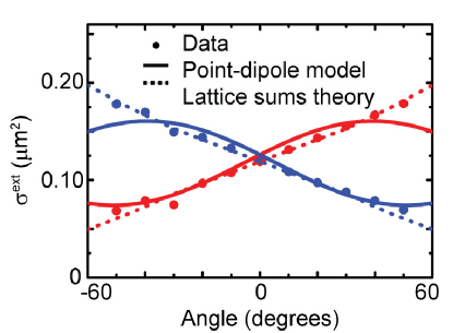
We quantify the polarizability tensor from the data by analyzing the effective extinction cross section per SRR defined as , where is the lattice pitch and is the minimum in transmission Sersic09 . Fig. 3 shows that this effective extinction cross section varies between 0.07 and m2 as the angle is swept from to (mirrored dependence for opposite handedness). For a single magneto-electric dipole scatterer Ref. Sersic11a predicts that the extinction cross section generally depends on angle as
| (2) |
Measurements on a single object would provide the electrodynamic Palik through the normal incidence extinction , while the maximum and minimum attained extinction encode electrodynamic polarizability eigenvalues via . Such a fit of the single object extinction to the measured effective extinction would provide , and expressed in units of the geometrical volume of the SRR (m3). However, in a lattice of SRRs, the response is modified by coherences such that , where a lattice sum Green function renormalizes the polarizability Abajo07 . We calculate lattice transmission by rigorous electrodynamic lattice sums involving all multiple-scattering interactions between SRRs Abajo07 . Consistent with our data, the calculated transmission shows strong optical activity under oblique incidence. We extract , , at =1600 nm from a comparison to data, highlighting that the response of SRR arrays is consistent with remarkably strong maximum magneto-electric cross coupling.
In Ref. Sersic11a we analyzed how electrodynamic scatterers with arbitrary polarizabilities of the form in Eq. (1) scatter. In that work, we realized that once one applies the optical theorem to a planar scatterer (in-plane , out-of-plane ), appears as the maximum value that – the crosscoupling after taking a common resonant frequency factor out of Eq. (1) footnote – can possibly attain to avoid violation of energy conservation. Here we claim that any planar circuit-derived scatterer is necessarily exactly at this upper bound, i.e., at maximum cross coupling. To prove this assertion we analyze a generic model for the polarizability of a planar scatterer under two general assumptions: (1) a linear response and (2) that an electric and magnetic dipole response originate from the same equation of motion for charge moving through the scatterer. Linear response implies , where () is in the plane (perpendicular to the plane) of the scatterer. Since and both derive from the same charge motion, and , where and are geometry-dependent constants. One now finds the electrostatic circuit polarizability as
| (3) |
For reciprocal materials, Onsager’s relations constrain and to be symmetric, as well as requiring . Taking out a common frequency factor that describes the circuit resonance, one finds that always take the form footnote
| (4) |
The surprise is that Onsager constraints leave no freedom to choose the off-diagonal coupling . Any planar circuit element is cross coupled, with cross coupling . Combining this finding with our result from Ref. Sersic11a we conclude that any planar circuit-derived scatterer is not just cross coupled, but that this coupling is at the maximum cross coupling limit. Maximum cross coupling means one vanishing eigenpolarizability , hence complete transparency of the scatterer for one handedness under oblique incidence, which means huge optical activity contrast.
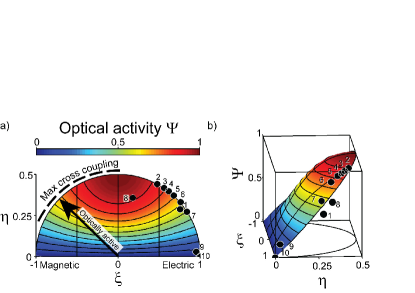
Based on our experiment, we can now assess whether the strong cross coupling in real scatterers is indeed close to the predicted maximum. From the polarizability we extracted from the very strong circular polarization contrast in extinction observed for split rings in Figure 3 we indeed find almost maximum cross coupling, since . Furthermore, we use full-wave simulations to examine the polarizability, and pseudo-chirality in extinction of many scatterers. We use 3D Surface Integral Equation (SIE) calculations Kern09 , to obtain full-wave solutions for archetypical metamaterial scatterers including SRRs, Omega particles with straight legs of different length, double SRRs and double-gap rings as shown in Fig. 1(b). We calculate scattering cross sections and polarizability tensors independently from each other. To extract the polarizability, we excite the same scatterer with six linearly independent illumination conditions, obtained as counter-propagating linearly polarized beams set in (out of) phase to yield just electric (magnetic) Cartesian excitation. We project the calculated scattered E-field evaluated on a spherical surface around the scatterer on vector spherical harmonics to retrieve and Muhlig11 . As a consistency check on the polarizability retrieved by matrix inversion we verify that the Onsager constraints are satisfied, which are not a priori assumptions in the retrieval. We summarize results for all scatterers in a ‘master plot’ that allows comparison independent of scatterer size. The scatterers are shown in Fig. 1 (b). As a first dimensionless variable we use , which equals for purely electric (magnetic) scatterers, and for equal electric and magnetic polarizability. As a dimensionless second variable we take the normalized cross coupling . The locus of maximum cross coupling is the ellipse . Fig. 4 shows that most metamaterial scatterers we analyzed have well away from , indicating significant magnetic polarizability. Furthermore all particles are essentially on the locus of maximum cross coupling, confirming our claim that bianisotropy is ubiquitous.
As third axis for the master plot we use a measure for optical activity in scattering. All scatterers we simulated show an angular dependence of the scattering cross section of the form in Eq. (2). The dimensionless parameter evaluated at 45∘ incidence angle quantifies the maximum attained difference in extinction (maximal always at 45∘) normalized to (twice) the angle-averaged extinction cross section . Fig. 4 shows versus and as predicted by point scattering theory. Evidently, optical activity is expected to be absent for zero cross coupling, and to increase monotonically as cross coupling increases. Very strong contrast in extinction per-building block is expected along most of the locus of maximum cross coupling, vanishing only for purely electric, and purely magnetic dipole scatterers (). The full-wave simulations show that all the commonly used metamaterial scatterers exhibit strong optical activity in surprisingly good agreement with the dipole model given that the circuit approximation, and the neglect of multipoles and retardation in Eq. 4 are very coarse assumptions. Freedom to deviate significantly from the dipole model requires multiple overlapping resonances in a single scatterer. Indeed, the most noted deviations occur for the object (8,9) which has two hybridized resonances of separate parts. Earlier findings based on symmetry arguments proposed that extrinsic 3D chirality requires loss Plum11 . We find that optical activity is in fact ubiquitous for planar magneto-electric scatterers, irrespective of absorption. The cancellation of optical activity for zero absorption noted by Plum11 does not occur in but occurs in special cases where observables are subject to additional symmetries, such as wave vector conservation in non-diffracting periodic systems.
To conclude, we have shown that planar metamaterial scatterers that rely on a single resonance to generate a simultaneous electric and magnetic response are maximally bianisotropic and strongly optically active, whether they exhibit geometrical chirality or not. Our findings have important implications for controlling bianisotropy independently of and in metamaterials, since they imply that it is fundamentally impossible to independently control bianisotropy for single resonant objects. The only route to avoid bianisotropy in lattices of resonators is to use heterogeneous lattices that contain distinct, or multi-resonant elements (e.g., double-split rings in Fig. 4) to independently generate and , or to use lattices of effectively larger ‘super-cells’ with rotated copies of the same building block to cancel off-diagonal coupling. Our results also hold important promise for enhancing far-field or near-field chirality Cohen10 in scattering applications where it is desired. In general, since maximum cross coupling is ubiquitous, optical activity is a very robust phenomenon that is easily extended to, e.g., finite clusters, random assemblies, or multi-element antennas. For instance, we predict that one can create chiral variants of the plasmon Yagi-Uda antenna to generate or selectively enhance circularly polarized single emitters.
Acknowledgements.
We thank Huib Bakker and Ad Lagendijk for fruitful discussions. This work is part of the research program of the “Stichting voor Fundamenteel Onderzoek der Materie (FOM),” which is financially supported by the “Nederlandse Organisatie voor Wetenschappelijk Onderzoek (NWO).” AFK acknowledges a VIDI fellowship funded by NWO.References
- (1) V. G. Veselago, Sov.Phys. USPEKHI 10, 509 (1968).
- (2) J. B. Pendry, Phys. Rev. Lett. 85, 3966 (2000); J. B. Pendry, Physics World 14, 47 (2001); C. M. Soukoulis, S. Linden, and M. Wegener, Science 315, 47 (2007); V. M. Shalaev, Nature Photonics 1, 41 (2007).
- (3) J. B. Pendry, D. Schurig, and D. R. Smith, Science 312, 1780 (2006).
- (4) U. Leonhardt, Science 312, 1777 (2006).
- (5) D. Schurig, J. J. Mock, B. J. Justice, S. A. Cummer, J. B. Pendry, A. F. Starr, and D. R. Smith, Science 314, 977 (2006).
- (6) J. Zhou, J. Dong, B. Wang, T. Koschny, M. Kafesaki, and C. M. Soukoulis, Phys. Rev. B. 79, 121104 (2009).
- (7) Z. Li, R. Zhao, T. Koschny, M. Kafesaki, K. B. Alici, E. Colak, H. Caglayan, E. Özbay, and C. M. Soukoulis, Appl. Phys. Lett. 97, 08190 (2010).
- (8) V. K. Valev, N. Srnisdorn, A. V. Silhanek, B. De Clercq, W. Gillijns, M. Ameloot, V. V. Moshchalkov, and T. Verbiest, Nano Lett. 9, 3945 (2009).
- (9) Y. Gorodetsky, N. Shitrit, I. Bretner, V. Kleiner, and E. Hasmanm Nano Lett. 9, 3016 (2009).
- (10) A. Drezet, C. Genet, J.-Y. Laluet, and T. W. Ebbesen, Opt. Express 16, 12559 (2008).
- (11) S. Zhang, Y.-S. Park, J. Li, X. Lu, W. Zhang, and X. Zhang, Phys. Rev. Lett. 102, 023901 (2009).
- (12) M. Decker, R. Zhao, C. M. Soukoulis, S. Linden and M. Wegener, Opt. Lett. 35, 1593 (2010).
- (13) E. Plum, J. Zhou, J. Dong, V. A. Fedotov, T. Koschny, C. M. Soukoulis, and N. I. Zheludev, Phys. Rev. B. 79, 035407 (2009).
- (14) J. K. Gansel, M. Thiel, M. S. Rill, M. Decker, K. Bade, V. Saile, G. von Freymann, S. Linden, and M. Wegener, Science 325, 1513 (2009).
- (15) J. B. Pendry, Science 306 1353 (2004).
- (16) R. Zhao, J. Zhou, Th. Koschny, E. N. Economou and C. M. Soukoulis, Phys. Rev. Lett. 103, 103602 (2009).
- (17) Z. Fan and A. O. Govorov, Nano Lett. 10, 2580 (2010).
- (18) E. Hendry, T. Carpy, J. Johnston, M. Popland, R. V. Mikhaylovskiy, A. J. Lapthorn, S. M. Kelly, L. D. Barron, N. Gadegaard, and M. Kadodwala, Nature Nanotech. 5, 783 (2010).
- (19) Y. Tang and A. E. Cohen, Phys. Rev. Lett. 104, 163901 (2010).
- (20) Y. Tang and A. E. Cohen, Science 332, 333 (2011).
- (21) I. V. Lindell, A. H. Sihvola, S. A. Tretyakov, and A. J. Viitanen, Electromagnetic Waves in Chiral and Bi Isotropic Media (Artech House, Norwood, MA, 1994).
- (22) N. Katsarakis, T. Koschny, M. Kafesaki, E. N. Economou, and C. M. Soukoulis, Appl. Phys. Lett. 84, 2943 (2004).
- (23) I. Sersic, C. Tuambilangana, T. Kampfrath and A. F. Koenderink, Phys. Rev. B 83, 245102 (2011). The appendix specifies the units also used in this Letter.
- (24) A. M. Kern and O. J. F. Martin, J. Opt. Soc. Am. A 26, 732 (2009). We use tabulated optical constants for gold Palik , and the following dimensions: inner/outer radii in m 0.74/1.19 (2-6), 1.6/2.5 and 2.7/3.6 (8), 2.7/3.6 (10), with a gap of 450 nm resp 200 nm for structures (2-6) resp. (10). For scatterers (2-6) we increased the outer arm length from 0 to 900 nm. Scatterer thickness is 30 nm throughout. The respective resonance wavelength of the scatterers in m are 1.600, 15.40, 16.06, 16.41, 16.80, 17.58, 1.544, 62.50, 23.25, and 16.50 for structures (1-10). Note that resonances (8,9) are two resonances in one structure.
- (25) In the static limit and are real in and Ohmic loss appears in in Eq. (4). The addition of radiation damping sets , and to be complex quantities even in absence of Ohmic damping Sersic11a .
- (26) C. Enkrich, M. Wegener, S. Linden, S. Burger, L. Zschiedrich, F. Schmidt, J. F. Zhou, Th. Koschny, and C. M. Soukoulis, Phys. Rev. Lett. 95, 203901 (2005).
- (27) I. Sersic, M. Frimmer, E. Verhagen and A. F. Koenderink, Phys. Rev. Lett. 103, 213902 (2009).
- (28) I. Sersic, C. Tuambilangana and A. F. Koenderink, New J. Phys. 13, 083019 (2011).
- (29) E. Plum, V. A. Fedotov, and N. I. Zheludev, J. Opt. 13, 024006 (2011).
- (30) B. Gompf, J. Braun, T. Weiss, H. Giessen, U. Hübner and M. Dressel, Phys. Rev. Lett. 106, 185501 (2011).
- (31) We define a dynamic by adding radiation damping to a static Sersic11a with Lorentzian resonance centered at 1600 nm, and with damping rate of gold from Handbook of Optical Constants of Solids, edited by E. D. Palik (Adacemic, Orlando, FL, 1985).
- (32) F. J. García de Abajo, Rev. Mod. Phys. 79, 1267 (2007).
- (33) S. Mühlig, C. Menzel, C. Rockstuhl, and F. Lederer, Metamaterials 5, 64 (2011).