Robust Nodal Structure of Landau Level Wave Functions Revealed by Fourier Transform Scanning Tunneling Spectroscopy
Abstract
Scanning tunneling spectroscopy is used to study the real-space local density of states (LDOS) of a two-dimensional electron system in magnetic field, in particular within higher Landau levels (LL). By Fourier transforming the LDOS, we find a set of radial minima at fixed momenta for the th LL. The momenta of the minima depend only on the inverse magnetic length. By comparison with analytical theory and numerical simulations, we attribute the minima to the nodes of the quantum cyclotron orbits, which decouple in Fourier representation from the random guiding center motion due to the disorder. Adequate Fourier filtering reveals the nodal structure in real space in some areas of the sample with relatively smooth potential disorder.
pacs:
73.43.-f, 73.22.-f, 73.43.Cd, 73.20.AtDirectly mapping the wave functions of electrons gives the most pertinent access to the quantum mechanical properties of matter Eigler ; Manoharan ; Manoharan2 ; Yazdani ; Maltezo . Under a perpendicular magnetic field in two-dimensional electron systems (2DES), self-interference of the circular electronic orbits leads to a standing wave pattern of probability density, as first calculated by Landau textbook . The kinetic energy becomes quantized into discrete Landau levels (LL) , with the cyclotron frequency, Planck’s constant, and characterizing the number of nodes in the LL wave functions. Experimental observation of this nodal structure has until now remained elusive. The 2DES are usually deeply buried in semiconducting heterostructures, which prevents the use of high resolution scanning tunneling spectroscopy (STS). Recently, the advent of surface 2DES in doped semiconductors Morg2003b ; Hash2008 ; Becker2010 , graphene Niim2009 ; Mill2010 and on the surface of topological insulators Top1 ; Top2 has in principle opened the way to such direct high resolution measurements. This should allow probing the internal structure of the LL wave functions.
However, the Landau energy levels are highly degenerate, so that the associated wave functions will be strongly disturbed by any perturbation such as disorder. One has, thus, to deal with the inherent complexity of disorder in spectroscopic measurements. More fundamentally, disorder is crucial for the understanding of universal quantized Hall conductance VonK1980 in 2DES. At high magnetic field, disorder essentially lifts the LL degeneracy keeping as a good quantum number due to the large cyclotron gap. The electronic motion is then largely decomposed into independent fast cyclotron orbit and slow drifting motion of the guiding center along equipotential lines of the smooth disorder landscape. Most of the equipotential lines in the bulk being closed, this picture provides a simple localization mechanism that ensures a reservoir of localized electronics states between LLs, ultimately responsible for the formation of wide quantized plateaus of Hall conductance textbook . This semiclassical picture was recently confirmed by STS real space imaging of the electronic probability density Hash2008 ; Mill2010 . The latter was found in the lowest LL, LL0, to follow equipotential lines with a transverse spread on the scale of the magnetic length . Within the higher LLs, LL for , the drift motion is expected to be accompanied by larger cyclotron orbits characterized by the quantum Larmor radii . This larger spread of the meandering LL wave functions in the transverse direction to the guiding center motion should contain signatures of the LL nodal structure for . Note that these nodes can be related to phase singularities of LL wave functions with a winding number Czerwinski ; Champel2007 . This topological origin confers some robustness to the nodal structure which should be viewed as a key property of quantum Hall states. The purpose of this Letter is to show how to reveal these interference effects.
The quantum states in disordered LLs are delicate to analyze in detail, because drift and cyclotron motion are, strictly speaking, not disentangled. We will show that a useful spectroscopic analysis can still be made by two-dimensional (2D) Fourier transform of the STS data, which allows to deconvolute the contribution from the discrete LL orbits and from the disorder induced drift motion. The nodal structure of LL is revealed by a succession of ring-like patterns in momentum-space, given by a set of fixed and disorder-independent minima within the momentum scale . Analytical and numerical calculations are performed to vindicate our findings. Moreover, a methodology to show the nodal structure in real-space is demonstrated.
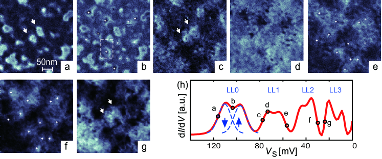
The 2DES was prepared by 1% monolayer Cs adsorption on an n-type InSb(110) surface Bett2001 with donor (acceptor) density m-3 ( m-3) Hash2008 . The STS measurements Hash2008 were performed in ultra-high vacuum at T and temperature K Wieb2004 . Figures 1(a)–(g) show images of the differential conductivity dd recorded within the same spatial area for seven different sample voltages spanning the four spin-split LLs from LL0 to LL3 [see the spatially averaged d/d curve shown in Fig. 1(h)]. These spatial maps represent the local density of states (LDOS) consisting of all wave functions at energy within the experimental energy resolution of 2.5 meV Hash2008 ; Morg2003a , see discussion in noteSupInfo . In the lower tail of LL0 [Fig. 1(a)], several spatially isolated closed loops are visible, which correspond to individual localized states encircling potential minima as shown in Ref. Hash2008 . The same states are visible within the lower tail of the higher spin level of LL0 [Fig. 1(b)], however, superimposed to the states marked by white crosses which belong to the upper tail of the lower spin level and encircle potential maxima. Similar patterns are found at the same positions in the lower tail of higher LLs [marked by arrows for LL1 in Fig. 1(c) and LL3 in Fig. 1(g)], but they are spatially wider and are, thus, more difficult to discriminate. The widening of the drift states marks the progressive increase of with . Careful inspection of the localized states in the LL’s lower tail [Figs. 1(a),(c),(g), see arrows] and in the upper tail [Figs. 1(b),(e),(f)] reveals that the closed loops exhibit more complex oscillatory patterns perpendicular to the loop in higher LLs.
In order to relate the oscillatory features to the nodal structure of the LL wave functions, we firstly overcome the difficulty that the cyclotron motion is randomly correlated to the guiding center motion. This partly masks the nodal structure within our real-space data. Note that LL mixing would also blur this structure. However, in the present experimental conditions (large cyclotron gap and smooth disorder, see Ref. Hash2008 ), LL mixing plays a negligible role (see discussion in noteSupInfo ). In this case, previous works Raikh1995 ; Champel2009 ; Champel2011 have demonstrated an exact decomposition of the LDOS as a function of position and energy :
| (1) |
Here, we neglect, for the sake of simplicity, thermal smearing effects and the experimental energy resolution, which could be implemented straightforwardly. corresponds to the guiding center spectral density in LL, which encodes the complicated dynamics induced by the disorder. The key object in Eq. (1) is the so-called structure factor
| (2) |
where is the Laguerre polynomial of degree containing oscillations (or, equivalently, nodes).
The structure factor is not strictly positive and, while associated with the quantum cyclotron motion in LL, cannot be interpreted directly as the wave function probability density. Instead, corresponds to a Wigner distribution Champel2009 , because the physical real-space of the guiding center coordinates is in fact associated to a pair of quantum conjugate variables Goerbig , owing to the commutation relation . The convolution given by Eq. (1) illustrates the difficulty in resolving in real-space the nodes of the Landau states that are built in the structure factor. Indeed, the sharp nodal structure of is not only blurred in , but the smeared nodal patterns must also follow the random meanders of the guiding center trajectories encoded in . However, by performing a 2D Fourier transformation (FT) of the LDOS, a simpler product form is achieved
| (3) |
where the FT of the structure factor reads:
| (4) |
For a smooth disorder potential characterized by a large correlation length , possesses disorder-induced structures mainly at short wave vectors , and should barely vary around the larger momentum scale . Thus, distinguishable momentum-variations in the FT of the LDOS (3) should arise from the universal structure factor (4). We now examine this issue both using our STS data and numerical simulations of a disordered 2DES at high field.
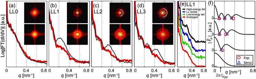
In order to reveal the nodal structure of LLs in momentum-space encoded into , we proceed with the FT of the LDOS images of Figs. 1(a) (LL0), 1(c) (LL1), 1(f) (LL2), and 1(g) (LL3). Since the FT of the LDOS displays sign changes due both to the structure factor and to the random spectral density in momentum space, we focus our discussion on the absolute value of the FT signal. We also use a voltage averaging of 2 mV of the data in order to improve contrast. The upper insets in Figs. 2(a)–(d) illustrate the resulting Fourier-transformed LDOS (FT-LDOS) images. They exhibit a single radial modulation for LL1, changing into double (LL2) and triple (LL3) radial modulations at the positions marked by dashed half circles. In order to smoothen the random contributions of the spectral density, we perform an angular average of the signal as shown by the curves (thick red lines) in Figs. 2(a)–(d). A consequence of this angular averaging is that deviations from perfect angular symmetry and noise within the experiments will add up to a (possibly -dependent) finite background. Therefore the expected zeros from the structure factors are shifted upwards and become minima. At LL0 [Fig. 2(a)], the resulting FT curve decreases monotonically, composing a disk structure in the FT-LDOS (upper inset). However, at LL1 [Fig. 2(b)], the FT curve exhibits a dip at nm-1 followed by a broad hump. This results in an additional ring-like structure surrounding a smaller disk in the FT-LDOS image (upper inset). The number of dips/humps in the FT curve, i.e. the number of additional rings in the 2D-image, increases to 2 at LL2 [Fig. 2(c)] and to 3 at LL3 [Fig. 2(d)]. This general trend is almost quantitatively reproduced by numerical Hartree simulations Sohr2007 ; Hash2008 [thin black lines in Fig. 2(a)–(d) and lower insets]. Note that especially the position of the minima in the simulated FT curve shows good agreement with the position of the dip in the experimental one. The simulations diagonalize the wave functions at T within a random disorder potential calculated using and of the InSb sample Sohr2007 ; Hash2008 . In order to transform the resulting 3D disorder potential into 2D, a folding with the confined wave function parallel to deduced from the triangular well approximation Ando1982 is used. The resulting 2D disorder is lower than in the experiment, since it ignores disorder from the Cs atoms Hash2008 . This lower disorder explains the stronger features in the simulated FT, however, without any effect on the position of the minima. Moreover, the position of the minima is robust within each disorder-broadened LL as shown in Fig. 2(e). The same dip position is observed for all voltages, i.e. for localized as well as for extended states. This is remarkable, since the corresponding real-space LDOS [Figs. 1(c)–(e)] shows very different patterns due to the complicated guiding-center motion. The FT results confirm experimentally that from Eq. 3 is dominated by the energy-independent structure factor at the large momentum scale . More precisely, the minima appearing at larger are direct fingerprints of the distinct nodal structure within each LL. Fig. 2(f) shows a direct comparison of the minima positions deduced from Fig. 2(a)–(d) with . The mimima from the FT of experiment (circles) and simulation (triangles) quantitatively match the minima in .
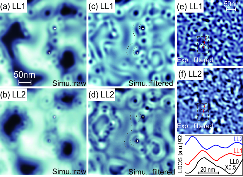
We now come back to the real space data, where the nodal structure can be observed by appropriate filtering. We use the fact that the disorder-induced drift is encoded up to nm-1 [black arrow in Fig. 2(f)] with our potential disorder typicalLength . The key characteristic feature of the real-space nodal structures is encoded at larger . Thus, by performing band-pass filtering of the FT-LDOS at large and a subsequent inverse Fourier transform, we can identify in real space the transverse nodes decoupled from the potential disorder (see Fig. 3). Since the scales of disorder and guiding center motion are not strongly different, adequate borders of the filtering are essential to improve the visibility of the nodal structure as outlined in the supplement noteSupInfo . In the numerical simulations, we find faint LDOS corrugations around the guiding center trajectories encircling the potential minima, marked by crosses in Figs. 3(a) and (b), while sharp oscillations perpendicular to the drift trajectory, marked by dotted lines, appear for LL1 (two maxima) and for LL2 (three maxima) after Fourier filtering software [Figs. 3(c),(d)]. The double and triple lines are distinct in flat areas of the potential (as marked), while in other areas where neighboring potential maxima are close, interference between their corresponding drift states prohibits a clear distinction. Within the experimental data, the nodal line structure is more difficult to find due to the large number of overlapping potential extrema. Careful comparison of the data obtained within different LLs in combination with Fourier filtering nevertheless reveals some regions where the transition from single via double to triple lines is observable. For example, consider the marked lines (in dashed rectangles) in the filtered LDOS of LL1, LL2 [Figs. 3(e),(f)] and LL0 noteSupInfo [see line sections in Fig. 3(g)].
In summary, FT of spatial STS data leads to a decoupling of the LDOS structures attributed to the quantum cyclotron orbit and to the complex disorder-dependent guiding-center motion. The former exhibits minima at universal for the th LL. These minima are associated to the oscillations of the Landau structure factor. By adequately Fourier filtering the real-space LDOS, the nodal structure is identified in real space. Our findings demonstrate that Landau quantization implies disorder independent universal features on the microscopic scale. This complements the well known universal quantum Hall plateaus.
Acknowledgements.
K.H. thanks T. Nakajima, M. Koshino, N. Shibata, H. Akera, K. Nomura for helpful discussions. We acknowledge DFG-projects Wi 1277/15-3, Mo 858/11-1, SFB 508-B4 and JSPS KAKENHI 21740219 for financial support. Part of the calculations were performed at the U.K. National Grid Service.References
- (1) M. F. Crommie, C. P. Lutz, and D. M. Eigler, Scinece 262, 218 (1993).
- (2) C. R. Moon, L. S. Mattos, B. K. Foster, G. Zeltzer, W. H. Ko, and H. C. Manoharan, Science 319, 782 (2008).
- (3) C. R. Moon, C. P. Lutz, and H. C. Manoharan, Nature Phys. 4, 454 (2008).
- (4) A. Richardella, P. Roushan, S. Mack, B. Zhou, D. A. Huse, D. D. Awschalom, and A. Yazdani, Science 327, 665 (2010).
- (5) T. Maltezopoulos, A. Bolz, C. Meyer, C. Heyn, W. Hansen, M. Morgenstern, and R. Wiesendanger, Phys. Rev. Lett. 91, 196804 (2003).
- (6) R. E. Prange and S. M. Girvin, The Quantum Hall Effect, (Springer, New York, 1987).
- (7) M. Morgenstern, J. Klijn, Chr. Meyer, and R. Wiesendanger, Phys. Rev. Lett. 90, 056804 (2003).
- (8) K. Hashimoto, C. Sohrmann, J. Wiebe, T. Inaoka, F. Meier, Y. Hirayama, R. A. Römer, R. Wiesendanger, and M. Morgenstern, Phys. Rev. Lett. 101, 256802 (2008).
- (9) S. Becker, M. Liebmann, T. Mashoff, M. Pratzer, and M. Morgenstern, Phys. Rev. B 81, 155308 (2010).
- (10) Y. Niimi, H. Kambara, and H. Fukuyama, Phys. Rev. Lett. 102, 026803 (2009).
- (11) D. L. Miller, K. D. Kubista, G. M. Rutter, M. Ruan, W. A. de Heer, M. Kindermann, P. N. First, and J. A. Stroscio, Nature Phys. 6, 811 (2010).
- (12) M. Czerwinski and D. Brown, Proc. Math. and Phys. Sc. 432, 43 (1991).
- (13) T. Champel and S. Florens, Phys. Rev. B 75, 245326 (2007).
- (14) T. Hanaguri, K. Igarashi, M. Kawamura, H. Takagi, and T. Sasagawa, Phys. Rev. B 82, 081305(R) (2010).
- (15) P. Cheng et al., Phys. Rev. Lett. 105, 076801 (2010).
- (16) K. von Klitzing, G. Dorda, and M. Pepper, Phys. Rev. Lett. 45, 494 (1980).
- (17) The deposited Cs induces a downwards band bending within the InSb and, thereby, creates the 2DES. See M. G. Betti et al., Phys. Rev. B 63, 155315 (2001).
- (18) J. Wiebe, A. Wachowiak, F. Meier, D. Haude, T. Foster, M. Morgenstern, and R. Wiesendanger, Rev. Sci. Instrum. 75, 4871 (2004).
- (19) M. Morgenstern, Surf. Rev. Lett. 10, 933 (2003).
- (20) Supplementary material, see EPAPS file…
- (21) M. E. Raikh and T. V. Shahbazyan, Phys. Rev. B 51, 9682 (1995).
- (22) T. Champel and S. Florens, Phys. Rev. B 80, 161311 (R) (2009); 82, 045421 (2010).
- (23) T. Champel, S. Florens, and M. E. Raikh, Phys. Rev. B 83, 125321 (2011).
- (24) M. O. Goerbig, Quantum Hall Effects (Lecture notes of “Les Houches” Summer School 2009), arXiv:0909.1998.
- (25) C. Sohrmann and R. A. Römer, New J. Phys. 9, 97 (2007).
- (26) T. Ando, A. B. Fowler, and F. Stern, Rev. Mod. Phys. 54, 437 (1982).
- (27) This is evaluated by nm-1 with nm being the typical correlation length of our disorder as determined from the distance of localized states, e.g. in Fig. 1(a).
- (28) The images are processed with WSxM. See I. Horcas, R. Fernández, J. M. Gómez-Rodriguez, J. Colchero, J. Gómez-Herrero, and A. M. Baro, Rev. Sci. Instrum. 78, 013705 (2007).