Utility of the inverse partial fluorescence for electronic structure studies of battery materials
Abstract
X-ray absorption spectroscopy (XAS) is one of the most widely used experimental techniques to study the electronic and spatial structure of materials. Fluorescence yield mode is bulk-sensitive, but has several serious problems coming from saturation effects. In this study, we show the usefulness of partial fluorescence yields in addressing these problems. We discuss the different behaviors of La2NiMnO6 and LiMnO2 at the Mn absorption edges. The total fluorescence yield produces misleading spectra for LiMnO2 due to the absence of high- (: atomic number) elements. We conclude that the measurement of the inverse partial fluorescence yield is essential in studies of LiMnO2, which is a hotly debated Li-ion battery material.
pacs:
71.30.+h, 71.28.+d, 73.61.-r, 79.60.Dppacs:
71.30.+h, 71.28.+d, 79.60.Dp, 73.61.-rX-ray absorption spectroscopy (XAS) is an experimental probe of the electronic and spatial structure of materials and is widely used in various fields of the natural sciences XASbook ; Stohr ; deGrootJES . XAS is the measurement of photo-absorption by excitation of a core electron into the unoccupied states as a function of photon energy. There are three measurement modes for XAS, the transmission mode, the electron yield (EY) mode, and the fluorescence yield (FY) mode. In the transmission mode, the intensity of the x-rays is measured in front of and behind the sample and the ratio of the transmitted x-rays is determined. Transmission mode experiments are standard for hard x-rays, while for soft x-rays they are difficult to perform due to the strong interaction of soft x-rays with the sample. An alternative to the transmission mode experiment has been provided by measuring the decay products of the core holes which are created in the absorption process. The decay products include electrons, photons, and ions escaping from the surface of the sample. The yield modes can be classified into the EY mode and the FY mode. The total electron yield (TEY) is the most widely used detection technique. The energy of the outgoing electrons is not selected and simply all the escaping electrons are counted. The signal is dominated by secondary electrons which are created in the cascade process of the Auger decay electrons. The estimated probing depth of this technique using soft x-rays is Å. Besides the EY mode, the fluorescent decay of the core hole can be also used for XAS measurements. In the FY mode, the photons created in the fluorescent process have a mean free path of the same order of magnitude as the incident x-rays. Consequently, the FY mode has a large probing depth ( Å in the soft x-ray region), and is particularly suitable for studying bulk electronic structures. The FY measurements can be performed by either the total fluorescence yield (TFY) or the partial fluorescence yield (PFY). In the TFY mode photons with any energy are counted, whereas the PFY mode uses an energy-sensitive detector and selects photons within a particular range of energies.
| (1) |
where
Here, is the contribution to the total attenuation coefficient from the excitation of core electron , and is the probability of fluorescence at energy resulting from electrons decaying to fill in the core hole left by . is an incident photon energy. is a constant given by the detector efficiency and the solid angle of the detector. and are the angles of incidence and emission, respectively, as measured from the sample surface.
A significant limitation of FY mode XAS arises from saturation effects Eisebitt , which distort peak intensities in the measured spectra and make FY non-linear with respect to the absorption coefficient. Recently, Achkar et al. introduced an alternative method to measure the absorption spectra which is bulk-sensitive and does not suffer from saturation effects Andrew . They used an energy-sensitive detector and measured the normal (non-resonant) x-ray emission spectrum (NXES) from a different element and absorption edge than the one probed resonantly with incident photons. The inverse of this NXES PFY is termed as the inverse partial fluorescence yield (IPFY), and is a function of the total x-ray absorption coefficient :
| (2) |
where , and . denotes the core electron, for example, O . In Eqn. (2), the constant is independent of and depends only weakly on over a narrow energy range and can be treated approximately as constant. Therefore, IPFY is proportional to the XAS plus an offset proportional to .
In this paper, we show the different behaviors of La2NiMnO6 and LiMnO2 at the Mn absorption edges. One can see that the TFY makes peak structures in La2NiMnO6 and dip structures in LiMnO2. This difference can be explained by the existence or absence of high- (: atomic number) elements such as La in this case. Then we show the usefulness of PFY and IPFY for the measurements of LiMnO2. This technique should become an indispensable tool for the measurement of systems without high- elements such as Li-ion battery materials.
The thin film of La2NiMnO6 was fabricated on a SrTiO3 substrate by the pulsed laser deposition technique, and the details were described in Refs. MPSingh1 ; MPSingh2 . The powder samples of LiMnO2 were synthesized by the procedure described in Refs. limno1 ; limno2 . The thickness of the thin films used for this study was 50 nm. XAS experiments were performed at 11ID-1 (SGM) of the Canadian Light Source. The TEY spectra were measured using drain current. The TFY spectra were measured with a channel plate detector. The PFY spectra were measured using a silicon drift detector with an energy-resolution of eV. The resolution power () was set to 5000. All the spectra were measured at room temperature.
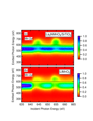
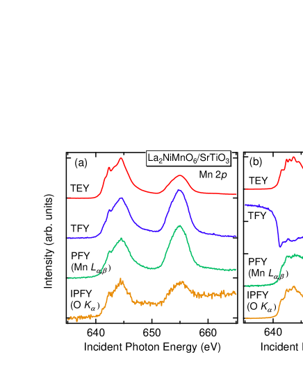
Figure 1 shows the energy resolved x-ray emission spectra of La2NiMnO6 (a) and LiMnO2 (b) (normalized to the incident photon intensity) as the incident photon energy is scanned through the Mn absorption edges. Emission spectra for several incident photon energies are shown in Fig. 2, and we can see x-ray emission peaks corresponding to the following two transitions Mn 640 eV (), and O eV (). As expected, the Mn emission increases as the incident photon energy passes through the Mn edges. In contrast, the O emission shows a small dip in the case of La2NiMnO6 (a), and a big dip in the case of LiMnO2 (b). The La in La2NiMnO6 has a much larger absorption cross section that the other elements in the material and dominates the total attenuation coefficient. Therefore, even at the Mn edges, the attenuation length of the incident photons does not change significantly and so the intensity of the O emission is not strongly reduced. When we measure the TFY from this sample, the absorption spectrum shows the expected positive structures, but they are slightly distorted by saturation effects, at the Mn edges. The situation in LiMnO2 is quite different. In this material, consisting of only low- elements, the penetration depth decreases greatly when exciting across the Mn edge. This leads to a significant decrease in the O emission that is larger in magnitude than the increase in Mn emission. The resulting TFY spectrum exhibits dip structures as shown in Fig. 3. The dip structures are not apparent in the PFY. For PFY, a threshold photon energy of 600 eV can be used to separate the O and Mn emissions, as shown in Figs. 1 and 2. The PFY from the Mn emission ( 600 eV) and the IPFY from the O emission ( 600 eV) are shown in Fig. 3.
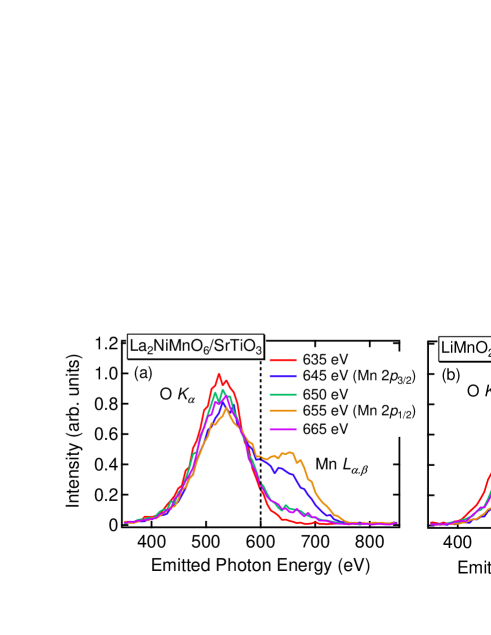
In the case of La2NiMnO6 (Fig. 3 (a)), the TFY shows less distortion by saturation effects than in LiMnO2. The Mn PFY displays stronger saturation effects, and the IPFY from O emission shows increased noise because the intensity of O emission does not change significantly at this edge, as shown in Fig. 2 (a). The IPFY of La2NiMnO6 also shows some distortion because the sample is only 50 nm thick. The IPFY method is based on the condition of total absorption, which, in this case, is not met at all photon energies. For LiMnO2 (Fig. 3 (b)), the Mn PFY has already been shown in Ref. [10], and is less significantly distorted by saturation effects. The IPFY derived from the O emission does not show any saturation effects, unlike the PFY from Mn emission, consistent with the report in Ref. [5]. This highlights that fact that TFY produces misleading spectra in many materials and that PFY is almost an indispensable tool to obtain bulk sensitive XAS spectra. Although reliable TEY spectra have also been measured on these materials, instances exist where surface contamination is significant or where the electronic states of the surface differ from the bulk LNO1 ; LNO2 and one must rely primarily on fluorescence detection. As demonstrated in this study, TFY is unsuitable for investigation of many Li-ion battery related materials, which is one of the most hotly debated topics in contemporary condensed-matter physics.
In conclusion, we have demonstrated the indispensability of the IPFY technique for XAS studies of low- battery related materials like LiMnO2. While TFY cannot be reliably applied to either LiMnO2 or La2NiMnO6, there is significantly less distortion in the La2NiMnO6 which we attribute to the presence of the strongly absorbing La atoms which moderate the change in penetration depth when exciting across the Mn edge. The PFY in both systems exhibits strong self-absorption effects. These effects are overcome by using the inverse of the O PFY (IPFY), which is a good representation of the Mn XAS in LiMnO2. As such low- systems are highly relevant battery materials, the IPFY technique will be a crucial tool for measuring accurate XAS spectra.
This research was made possible with financial support from the Canadian funding organizations NSERC, CFI, and CIFAR. This research is granted by the Kao Foundation and also by the Japan Society for the Promotion of Science (JSPS) through the “Funding Program for World-Leading Innovative R&D on Science and Technology (FIRST Program),” initiated by the Council for Science and Technology Policy (CSTP).
References
- (1) F. de Groot and A. Kotani, Core Level Spectroscopy of Solids (CRC Press, New York, 2008).
- (2) J. Stohr, NEXAFS Spectroscopy (Springer, New York, 1996).
- (3) F. M. F. de Groot, J. Electron. Spectrosc. Relat. Phenom. 67, 529 (1994).
- (4) S. Eisebitt, T. Boske, J.-E. Rubensson, and W. Eberhardt, Phys. Rev. B 47, 14103 (1993).
- (5) A. J. Achkar, T. Z. Regier, H. Wadati, Y.-J. Kim, H. Zhang, and D. G. Hawthorn, Phys. Rev. B 83, 081106 (2011).
- (6) M. P. Singh, C. Grygiel, W. C. Sheets, P. Boullay, M. Hervieu, W. Prellier, B. Mercey, C. Simon, and B. Raveau, Appl. Phys. Lett. 91, 012503 (2007).
- (7) M. P. Singh, K. D. Truong, S. Jandl, and P. Fournier, Phys. Rev. B 79, 224421 (2009).
- (8) Z.-F. Huang, F. Du, C.-Z. Wang, D.-P. Wang, and G. Chen, Phys. Rev. B 75, 054411 (2007).
- (9) F. Du, Z.-F. Huang, C.-Z. Wang, X. Meng, G. Chen, Y. Chen, and S.-H. Feng, J. Appl. Phys. 102, 113906 (2007).
- (10) H. Wadati, D. G. Hawthorn, T. Z. Regier, G. Chen, T. Hitosugi, T. Mizokawa, A. Tanaka, and G. A. Sawatzky, Appl. Phys. Lett. 97, 022106 (2010).
- (11) L. A. Montoro, M. Abbate, E. C. Almeida, and J. M. Rosolen, Chem. Phys. Lett. 309, 14 (1999).
- (12) Y. Koyama, T. Mizoguchi, H. Ikeno, and I. Tanaka, J. Phys. Chem. B 109, 10749 (2005).