Integrated liquid-core optical fibers — ultra-efficient nonlinear liquid photonics
Abstract
We have developed a novel integrated platform for liquid photonics based on liquid core optical fiber (LCOF). The platform is created by fusion splicing liquid core optical fiber to standard single-mode optical fiber making it fully integrated and practical - a major challenge that has greatly hindered progress in liquid-photonic applications. As an example, we report here the realization of ultralow threshold Raman generation using an integrated filled LCOF pumped with sub-nanosecond pulses at 1064nm and 532nm. The measured energy threshold for the Stokes generation is 1nJ, about three orders of magnitude lower than previously reported values in the literature for hydrogen gas. The integrated LCOF platform opens up new possibilities for ultralow power nonlinear optics such as efficient white light generation for displays, mid-IR generation, slow light generation, parametric amplification, all-optical switching and wavelength conversion using liquids that have orders of magnitude larger optical nonlinearities compared with silica glass.
pacs:
42.81.-i, 42.82.-m, 42.65.Dr, 78.30.C-The liquid state of matter is widespread in nature and possesses outstanding optical properties. For that reason, researchers have been attempting to harness liquids (or fluids) for different applications in photonics Psaltis2006 ; Monat2007 . However, it is quite difficult at the moment to find a real application in photonics that is based on this state of matter. The reason is the lack of suitable practical technology that allows working with long path-length liquids without the typical problems associated with diffraction, loss, and maintaining high intensity over the length. Liquid-core optical fiber (LCOF) was recognized very early Ippen1970 ; STONE1975 as a great platform to investigate and explore optical properties of liquids. LCOF is normally created by filling a small capillary with an appropriate liquid which should be transparent at the wavelength of interest and have a refractive index slightly higher than that of the capillary’s material to provide optical waveguiding via total internal reflection. Hollow-core photonics crystal fibers (HC-PCF) are also interesting structures where liquids or gases have been filled into the region around the hollow-core. Several interesting applications of HC-PCF have been recently investigated Benabid2002 ; Larsen2003 ; Benabid2005 ; Bethge2010 . These devices (LCOF and HC-PCF) make long interaction length with high optical field confinement possible, helping to enable nonlinear optical effects at extremely low power levels. Many interesting applications of LCOF have also been proposed and reported in the literature CHRAPLYVY1981 ; BRIDGES1982 ; HE1995 ; Dasgupta1998 ; Dallas2004 . These prior works demonstrated the great potential of LCOF. However, early experiments required free space alignment to launch the light into the core of the LCOF rendering the use of liquid unpractical. Thus, even though promising results were obtained, the full potential of liquid photonics were not realized due to the lack of best performance and it has not been used in real applications. Here, we show that low loss fusion splicing of liquid core optical fiber to standard single-mode optical fiber not only results in an integrated practical and compact set-up but also it leads to about three-orders of magnitude better nonlinear performance compared with early experiments Benabid2002 ; Benabid2005 . As an example, we demonstrate ultra-low threshold of 1 nJ stimulated Raman scattering in an integrated filled LCOF pumped with sub-nanosecond pulses at 1064nm and 532nm compared with 800 nJ in prior experiments Benabid2002 ; Benabid2005 .
There are two suitable platforms that provide long interaction length and strong field confinement namely capillary tubing or HC-PCF. Generally, working with a liquid filled HC-PCF or capillary requires free space coupling into the small guiding core. It would be desirable to be able to splice these specialty fibers to standard single-mode fiber while still being able to fill the liquid of interest into the hollow region. To date, we have tried several different approaches to achieve this. Mechanical splicing is simple (there is always a small gap between the fibers for liquid access) but the structure is not very stable and the insertion loss is normally quite high. Femtosecond laser drilling after a regular splice is another interesting approach but creates small debris that could block the capillary creating significant power loss. The best approach that we have found so far is splicing standard single-mode fiber to the capillary while leaving a small gap for liquid access (see below).
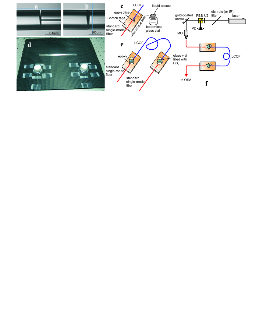
In our experiments, we use fused silica capillaries. They have different inner tube diameters (10 , 5 and 2 ), the outer diameter is around 125 matching well with standard single-mode fibers. To perform the splice, the capillary is cleaved at zero degrees (a straight angle) but the standard fiber is cleaved with an angle of 3-10 degrees (which helps to create a small gap after the fusion splice for liquid access). By optimizing the parameters of the heat source hole-collapse could be avoided and a relatively strong joint with a small gap for liquid access could be formed [Fig. 1(a)]. We have made a similar splice of SMF28 to another segment of SMF28 [Fig. 1(b)] and the loss of the transition was measured to be only around 0.1 dB. This indicates that the small gap left after the splice does not create appreciable loss. Due to the fact that the fibers are fused only in a small area the joint is not as strong as a standard fusion splice. However, the structure could be handled and transported (with some care) to a holder (access port) where it can be fixed permanently using an appropriate epoxy [Fig. 1(c)]. A similar gap-splice is made at the other end of the capillary tubing at a certain length to create the second access port for liquid filling. After filling with the liquid the access ports could be sealed and the structure remains stable for weeks [Figs. 1(d)-1(e)]. This technique integrates LCOF with standard optical fiber in a compact and stable package without the need for free space alignment or complicated liquid handling procedures. We have successfully used these devices in a few applications including Raman spectroscopy, supercontinuum generation and low threshold Raman generation, as described below.
Stimulated Raman scattering (SRS) is a nonlinear optical process in which an incoming photon interacts with a coherently excited system resulting in generation of new frequencies with very high conversion efficiency. SRS is useful in wavelength conversion, amplification, generation of ultra-short (atto-second) optical pulses Harris1998 ; Sokolov1999 ; Rong2005 ; Couny2007 ; Jones2011 , precision spectroscopy and microscopy Dudovich2002 ; Cheng2004 ; Freudiger2008 . SRS occurs when the pump power reaches a certain threshold to provide enough gain for the Stokes wave. The threshold peak power can be estimated using the following simple formula AgrawalBook
| (1) |
where in the present case the effective area is , the Raman gain coefficient for is at 532 nm Colles1969 , and the effective interaction length is .
We used a frequency doubled microchip laser (JDSU) that emits sub-nanosecond ( 500ps) Q-switched pulses as the pump source. The repetition rate of the source is 1.5kHz. The laser beam is coupled into a short piece (1m) of Corning HI1060 fiber using a microscope objective and translation stages as shown in Fig. 1(f). The coupling efficiency is . The coupled power into the standard fiber is adjusted using a combination of a half waveplate and a polarizing beam splitter. For experiments in the visible, an IR filter is used to remove the residual 1064nm pulses. For experiments using 1064nm wavelength, the IR filter is replaced by a dichroic filter to remove the visible green beam.
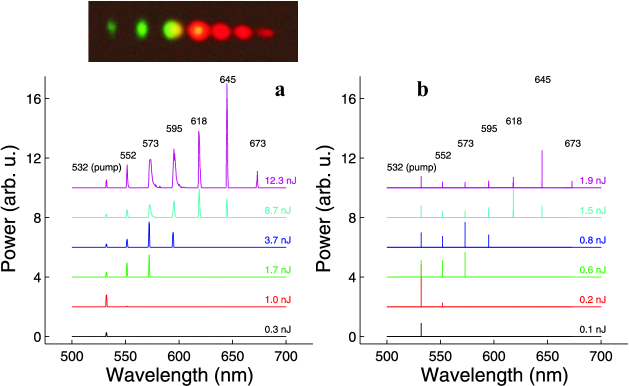
After the coupling step, light is launched into the integrated LCOF by simply splicing to the HI1060 fiber at one end. Figure 2(a) shows the evolution of the laser output after propagating through the filled LCOF. Several orders of Stokes Raman generation are seen as the pump power is increased. The threshold of stimulated Raman generation is at an extremely low pump pulse energy of 1nJ. This energy threshold is near three orders of magnitude lower than the value reported for hydrogen filled HC-PCF of similar length Benabid2002 . The ultralow threshold observed in our experiment can be attributed to the unprecedented confinement of the optical field ( 2micron core size), the long propagation length ( 1m), and the large Raman gain coefficient of . Using Eq. (1), we obtain an estimated threshold pump peak power of 0.4W at 532 nm pump wavelength which is consistent with the low-power threshold observed experimentally (2 W). We obtain the same threshold value when we numerically solve the coupled amplitude equations in the picosecond regime AgrawalBook .
In Fig. 2(a), up to 6 orders of stimulated Raman scattering are generated at only 12nJ of coupled pump pulse energy. We expect to see more Raman lines at higher pulse energies but they would be out of the measurement range of the OSA. We also observed broadening of the higher order Stokes lines. Broadening of stimulated Raman lines was also observed and explained by N. Bloembergen in Ref. Bloembergen1966 . Detailed understanding of the difference in the level of broadening for different orders is quite complex and is beyond the scope of this paper.
In the inset of Fig. 2(a), we nicely see multiple Raman lines that are separated in space using a prism made of SF10 glass. Due to the strong residual absorption of at 532nm we observed gradual reduction in transmission of the pump light due to heating. The capillary was eventually (in matter of 30 minutes) blocked and re-splicing of the fibers was required to observe the stimulated Raman generation process again. This thermally induced degradation was not observed when the fiber was pumped at 1064nm even at the highest available pulse energy ( 300nJ) for a few weeks.
Calculations of the higher-order Stokes generation are carried out based on the coupled equations presented in Refs. Bertoni1997 ; Min2003 . Explicitly, these coupled equations read
| (2) | ||||
| (3) | ||||
| (4) |
The wavelength-dependent normalized [with respect to the effective area ] Raman gain coefficients and for the space-time dependent pump and each Stokes line up to the Mth order enter, respectively, while dispersion and nonlinearities have been neglected as a good approximation due to the long pump duration. Figure 2(b) shows the calculated output spectra for increasing pump pulse energies. We notice that the number and position of Raman lines and their relative heights are well reproduced by theory. We observe that up to 6 Raman orders are visible at a pump pulse energy of 2 nJ. At lower pulse energies, only lower-order Raman lines are present, in good agreement with the experiment [Fig. 2(a)]. The difference between experiment and theory can be explained by the variation of the core size along the fiber, uncertainties in the Raman gain coefficient and the partially polarized input pump (due to propagation through a long segment of non-polarization preserving fiber).
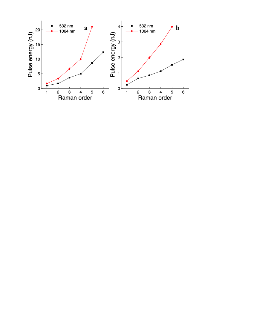
The measured energy corresponding to the generation of different orders of stimulated Raman scattering is shown in Fig. 3(a). The threshold energy for the 1064 nm pump wavelength is higher than in the case of the 532nm pump, which is expected since the Raman gain coefficient is lower at longer wavelength AgrawalBook ; YablonBook . Figure 3(b) shows the corresponding calculations which are in good agreement with Fig. 3(a). We observe a linear dependence in the theory as observed in experiment for low pump powers [Fig. 3(a)]. The deviation from the linear dependence as seen in the experimental data [Fig. 3(a)] at higher pump powers is conjectured to come from the higher absorption loss (due to water contamination) at longer wavelengths, or possibly reduced confinement and hence increased effective area for the longer wavelength Raman lines.
The reduction of Raman threshold power in LCOF should allow the use of low cost diode pumped lasers to create new frequencies. For example, we can envision the use of this platform to generate the required laser lines (red, green and blue) for future color TV display. Atto-second pulse generation via stimulated Raman scattering should also benefit from the low power threshold demonstrated here as well. The development of integrated LCOF is likely to lead to rapid progress of other important applications in nonlinear optics such as supercontinuum generation, mid-IR generation, slow light, all-optical switching and wavelength conversion. The prospects from practical liquid photonics appear to be quite bright. We further note that the recent development of organic materials Hales2010 with tremendous molecular hyper-polarizability (1000x) provides a route to pJ level operating energies. In addition, the gap-splicing technique reported here can be used with HC-PCF to open up the possibility of changing the gas under investigation on the same platform. This should be useful in applications involving gas sensing or breath analysis Thorpe2006 .
Acknowledgement: This work was supported by the DARPA ZOE program (Grant No. W31P4Q-09-1-0012), the CIAN ERC (Grant No. EEC-0812072), and the USAF, AFRL COMAS MURI program (Grant No. FA9550-10-1-0558).
References
- (1) D. Psaltis, S. R. Quake, and C. Yang, Nature 442, 381 (2006)
- (2) C. Monat, P. Domachuk, and B. J. Eggleton, Nature Photon. 1, 106 (2007)
- (3) E. P. Ippen, Appl. Phys. Lett. 16, 303 (1970)
- (4) J. Stone, Appl. Phys. Lett. 26, 163 (1975)
- (5) F. Benabid, J. C. Knight, G. Antonopoulos, and P. S. J. Russell, Science 298, 399 (2002)
- (6) T. T. Larsen, A. Bjarklev, D. S. Hermann, and J. Broeng, Opt. Express 11, 2589 (2003)
- (7) F. Benabid, F. Couny, J. C. Knight, T. A. Birks, and P. S. J. Russell, Nature 434, 488 (2005)
- (8) J. Bethge, A. Husakou, F. Mitschke, F. Noack, U. Griebner, G. Steinmeyer, and J. Herrmann, Opt. Express 18, 6230 (2010)
- (9) A. R. Chraplyvy and T. J. Bridges, Opt. Lett. 6, 632 (1981)
- (10) T. J. Bridges, A. R. Chraplyvy, J. G. Bergman, and R. M. Hart, Opt. Lett. 7, 566 (1982)
- (11) G. S. He, J. D. Bhawalkar, C. F. Zhao, C. K. Park, and P. N. Prasad, Opt. Lett. 20, 2393 (1995)
- (12) P. K. Dasgupta, Z. Genfa, S. K. Poruthoor, S. Caldwell, S. Dong, and S. Y. Liu, Anal. Chem. 70, 4661 (1998)
- (13) T. Dallas and P. K. Dasgupta, TrAC-Trend. Anal. Chem. 23, 385 (2004)
- (14) S. E. Harris and A. V. Sokolov, Phys. Rev. Lett. 81, 2894 (1998)
- (15) A. V. Sokolov, D. D. Yavuz, and S. E. Harris, Opt. Lett. 24, 557 (1999)
- (16) H. S. Rong, A. S. Liu, R. Jones, O. Cohen, D. Hak, R. Nicolaescu, A. Fang, and M. Paniccia, Nature 433, 292 (2005)
- (17) F. Couny, F. Benabid, P. J. Roberts, P. S. Light, and M. G. Raymer, Science 318, 1118 (2007)
- (18) A. M. Jones, A. V. V. Nampoothiri, A. Ratanavis, T. Fiedler, N. V. Wheeler, F. Couny, R. Kadel, F. Benabid, B. R. Washburn, K. L. Corwin, and W. Rudolph, Opt. Express 19, 2309 (2011)
- (19) N. Dudovich, D. Oron, and Y. Silberberg, Nature 418, 512 (2002)
- (20) J. X. Cheng and X. S. Xie, J. Phys. Chem. B 108, 827 (2004)
- (21) C. W. Freudiger, W. Min, B. G. Saar, S. Lu, G. R. Holtom, C. W. He, J. C. Tsai, J. X. Kang, and X. S. Xie, Science 322, 1857 (2008)
- (22) G. P. Agrawal, Nonlinear Fiber Optics (Academic Press, San Diego, 2007)
- (23) M. J. Colles, Opt. Commun. 1, 169 (1969)
- (24) N. Bloembergen and P. Lallemand, Phys. Rev. Lett. 16, 81 (1966)
- (25) A. Bertoni, Opt. Quant. Electron. 29, 1047 (1997)
- (26) B. Min, T. J. Kippenberg, and K. J. Vahala, Opt. Lett. 28, 1507 (2003)
- (27) A. D. Yablon, Optical fiber fusion splicing (Heidelberg, Germany: Springer-Verlag press, 2005)
- (28) J. M. Hales, J. Matichak, S. Barlow, S. Ohira, K. Yesudas, J. L. Bredas, J. W. Perry, and S. R. Marder, Science 327, 1485 (2010)
- (29) M. J. Thorpe, K. D. Moll, R. J. Jones, B. Safdi, and J. Ye, Science 311, 1595 (2006)