Bistatic scattering characterization of a three-dimensional broadband cloaking structure
Abstract
Here we present the results of full experimental characterization
of broadband cloaking of a finite-sized metallic cylinder at
X-band. The cloaking effect is characterized by measuring the
bistatic scattering patterns of uncloaked and cloaked objects in
free space and then comparing these with each other. The results
of the measurements demonstrate a broadband cloaking effect and
are in good agreement with numerical predictions.
I Introduction
The concept of electromagnetic cloaking has been found by many as an exciting example of the power of artificial electromagnetic materials (metamaterials). The concepts of transformation optics Leonhardt_Science ; Pendry_Science and scattering cancellation Alu_transparency ; Alu_review describe different ways of making scattering objects invisible, that is, reducing the total scattering cross section of an object ideally to zero. First experimental proofs of reduction of the total scattering from specific objects with these techniques have been provided by measuring the microwave field distributions near cloaked and uncloaked objects.Alu_measurement ; Smith_measurement
Recently, some alternative ways of achieving electromagnetic cloaking by employing waveguiding structures instead of complex materials have been proposed.Alitalo_review1 ; Alitalo_review2 These structures are composed of simple transmission lines or specifically shaped metallic structures that enable the electromagnetic wave either to go through the object Alitalo_TAP or to go around the object.MPcloak_PRL ; MPcloak_PRB Both these cloaking methods have been already studied numerically and experimentally. However, the experimental results for these structures were obtained in a rectangular waveguide setup, which does not allow the analysis of the total scattering cross sections or total scattering widths.
In this paper we describe microwave measurements at X-band of the bistatic scattering patterns of a finite-sized waveguiding cloak structure composed of stacked conical metal plates (therefore also called the “metal-plate cloak”).MPcloak_PRL ; MPcloak_PRB The cloaking effect is experimentally characterized by measuring the bistatic scattering patterns and comparing the total scattering widths of both uncloaked and cloaked objects. In addition to bistatic measurements, we employ the forward scattering theorem FWtheorem to evaluate the total scattering width using only the fields scattered in the forward direction. It is shown that the both approaches agree well with the numerical results.
It should be noted that the previous experimental demonstrations of reduction of total scattering widths by cloaking devices Alu_measurement ; Smith_measurement have been obtained by emulating infinitely long structures, since in both cases the measurements were carried out in a parallel-plate waveguide instead of free space. Here we carry out the measurements in free space conditions, using two antennas to measure the scattered fields produced by finite-sized objects. In addition to measurements we also present the corresponding numerical results for the total scattering widths and bistatic scattering patterns that are obtained with the commercial numerical software ANSYS HFSS.HFSS
II Geometry and dimensions of the cloak structure
The cloak geometry is the same as presented in Ref. 11, see Fig. 1. The conical metal plates, realized from and modelled as copper, form a periodic structure that surrounds a metal cylinder which is the object to be cloaked. The plates form a set of waveguides into which the electromagnetic wave with the electric field parallel to the axis of the cylinder can couple to. The wave travels inside the structure, with very weak reflections, around the cylinder placed in the center. Essentially this cloaking device is designed to work for objects that are electrically small since the wave inside the cloak must travel a distance larger than the wave that travels in free space along a straight line. However, it has been shownMPcloak_PRB that the diameter of the cloaked cylinder can be as large as about one wavelength without much compromising the cloaking effect. Therefore we use the structure and dimensions presented in Ref. 11 to demonstrate the cloaking of a metal (brass) cylinder having the diameter of 30 mm at X-band (specifically, in the band 8.2 GHz – 12.4 GHz). The optimized dimensions for cloaking at frequencies around 10 GHz are shown in Table I. A dielectric support of height and thickness has been added between two adjacent metal plates to enable practical realization of the structure. This dielectric is Rohacell® 51 HFRohacell and is numerically modelled as having the relative permittivity of and loss tangent of . These material properties are so close to the free space values that the layers do not practically affect the cloak’s operation, as can be concluded by comparing the numerical results shown later in this paper with the results presented in Ref. 11.
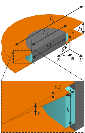
| 30 mm | 9.2 mm | 6 mm | 61 mm | 32 mm | 0.1 mm | 2 mm |
III Experimental setup for measuring the bistatic scattering
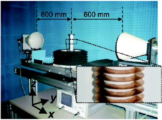
We use a bistatic measurement setup composed of two antennas to measure the fields scattered by uncloaked and cloaked objects in various directions in the -plane. The transmitting antenna is fixed at while the receiving antenna is swept from to . Both antennas are operating with the vertical polarization (electric field parallel to the -axis). See Fig. 2 for a photograph of the setup. The transmitted and received signals are measured with a vector network analyzer (Agilent HP 8719D) in the band 8.2 GHz-12.4 GHz with 401 frequency points. Both antennas are equipped with microwave lenses that focus the antenna beams exactly on the object that is measured. The beam’s half-power width at the focus is approximately 45 mm and the measured structures are made considerably higher than the beamwidth to avoid any scattering effects caused by the finite height. The cloak to be measured is made of 20 unit cells shown in Fig. 1, i.e., the cloak (and the cloaked cylinder) has the height 184 mm.
Under these conditions the bare cylinder and the cloak scatter mostly in the -plane and therefore we can characterize the cloaking effect using the total scattering width instead of the total scattering cross section. We measure the scattering pattern of the cloaked/uncloaked object for angles since the scattering structures are symmetrical with respect to the -plane and the measurement of angles is not possible due to the finite size of the antennas. However, the lack of data for angles will not be problematic since most of the scattering occurs in the forward direction (close to ), and we can compare our measured results with numerical results in the same angular range. All the measurements presented in this paper have been carried out with an angular step of .
For every angle we measure the complex scattering parameter of the studied object (). In addition, the measurement is repeated without the scatterer (, i.e., transmission in free space) to account for the crosstalk between the transmitting and receiving antennas. A value directly proportional to the scattered electric field is then obtained from these two measurements with
| (1) |
where is the frequency and is the angle in the -plane.
One of the most practical ways to characterize a cloak and to determine the efficiency of cloaking is to study the total scattering width of the cloaked object, normalized by the total scattering width of the uncloaked object. The same analysis has been used in Ref. 5. The scattered field intensities are integrated over the -plane for both objects. The normalized total scattering width (, i.e., the total scattering width of object 1 normalized by the total scattering width of object 2) is therefore
| (2) |
where “O1” stands for object 1 and “O2” for object 2.
All our scattering objects are cylindrically symmetric, so it would be enough in (2) to integrate only from to , but since we are limited in the angular range of the measurement setup, we have to approximate (2) by integrating from to . However, the backscattered field at can be determined by measuring the reflection coefficient () of the transmitting antenna and equating it to the scattered field. We are not using this value of the scattered field in the integration, but we can use it for making sure that the scattering objects behave as expected also in the back direction.
The forward scattering (or optical) theorem FWtheorem states that the total scattering width (or cross section) is directly related to the complex field scattered in the forward direction. This theorem offers a convenient way to estimate the total scattering widths of the objects studied here since only the scattered fields at need to be considered. To employ the theorem, we need to find the far-field scattering coefficients FWtheorem of the studied objects. These are found by using a calibration scatterer, such as a metal cylinder. Specifically, the total scattering width of an object is found with
| (3) |
where is the wavenumber, is the analytically known FWtheorem far-field scattering coefficient of the calibration object, and , are the measured scattered electric fields of the studied object and calibration object, respectively. The normalized total scattering width is obtained by taking the ratio of of two different objects.
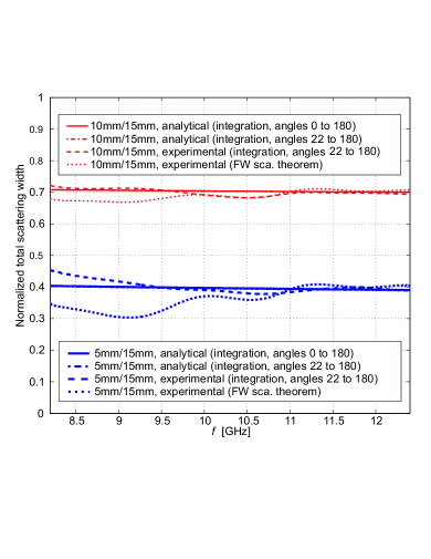
We first verify the operation of the measurement setup by measuring metal cylinders of different diameters so that we can compare the measured scattering widths with the known analytical results. In this way we can estimate the error which is introduced by integrating in (2) only over the limited range of angles. We measure three different metal cylinders with radii 5 mm, 10 mm, and 15 mm (the height of all cylinders equals 184 mm). Then we use (1) for the scattered fields and (2) to obtain the normalized total scattering widths using the integration method. We also employ the forward scattering theorem (3), where we use the cylinder with radius 10 mm as the calibration object. Fig. 3 presents analytical and experimental results for the normalized total scattering widths of various cylinders. The measured results agree well with the analytical ones, although a little bit of fluctuation is naturally seen in the measured values. It should be noted that two analytical results are shown for comparison: the exact solution of (2), and one obtained by integrating in (2) from to . These analytical curves overlap and with the scaling in the plot it is impossible to distinguish these results from each other. This is expected since the approximation done in the integration disregards only a small portion of the angular range, and moreover, the objects scatter much more in the forward direction than in the back direction. One important factor is also that close to the back direction (in to ), the scattering cross section is stable with respect to the angle. Also the forward scattering theorem gives a reasonable result, although we can conclude that the integration method gives a more accurate result. The reason for this is that the scattered field in the forward direction () has larger measurement error than the scattered fields in other directions. This is very much expected since for small scatterers and for angles close to , the parameters and are at maximum and close to each other which leads to the larger error.
IV Experimental and numerical results of cloaking
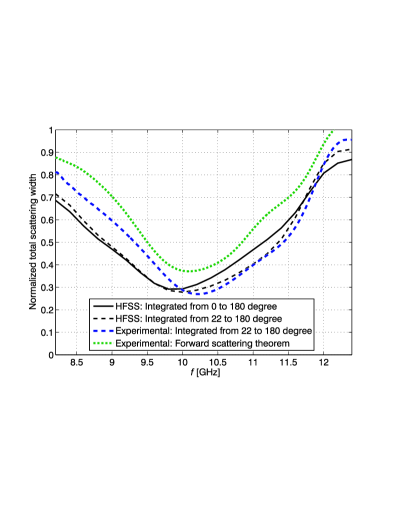
A cloak with 20 unit cells of Fig. 1 was assembled on a metal cylinder having the diameter 30 mm. The cloaked and uncloaked cylinders were then measured as described above. Fig. 4 presents the normalized total scattering width for the cloak studied in this paper, demonstrating that the cloak reduces the total scattering width of the uncloaked metal cylinder by about 70% in maximum. The wide operation bandwidth is also demonstrated, since the cloak is shown to reduce the total scattering width of the cylinder by more than 50% in a relative frequency bandwidth of about 20%. The center of the cloaking band is at around 10 GHz, as predicted by numerical results. It should be emphasized that based on the results of Fig. 3, the integration method is expected to be more accurate than that based on the forward scattering theorem. However, it is clear that the both curves demonstrate the cloaking effect.
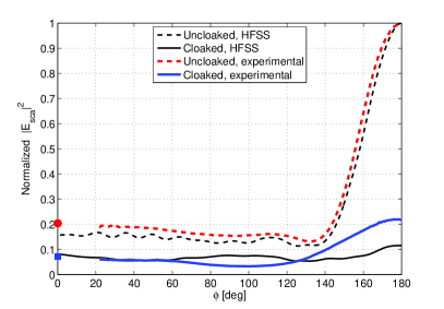
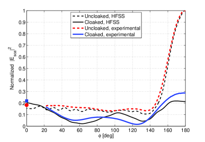
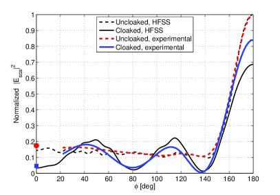
Although the most important figure of merit for the cloak is the normalized total scattering width, it is interesting to look at the angular dependence of the bistatic scattering patterns at fixed frequencies. Fig. 5 presents the normalized scattered field intensities as a function of for frequencies 10 GHz, 11 GHz, and 12 GHz. It is obvious that the experimental results differ somewhat from the numerical ones, but the numerical and experimental results for the overall performance of the cloak are in good agreement.
V Conclusions
Experimental confirmation of scattering reduction by a finite-sized metal-plate cloak operating in the X-band has been presented. A bistatic free space measurement setup has been established for this purpose. The efficiency of the cloak has been demonstrated by determining the total scattering widths of an uncloaked and cloaked metallic cylinder of finite height. Measurement results have been compared with numerical ones. The results are in good agreement with each other. The cloak has been shown to reduce the total scattering width of the cylinder by more than 50% in a relative frequency bandwidth of about 20% around 10 GHz.
This work has been partially funded by the Academy of Finland and Nokia through the center-of-excellence program. The work of P. Alitalo has been supported by the Academy of Finland through post-doctoral project funding. P. Alitalo acknowledges the work of Mr. Eino Kahra in helping in the manufacturing of the cloak.
References
- (1) U. Leonhardt, Science 312, 1777 (2006).
- (2) J. B. Pendry, D. Schurig, and D. R. Smith, Science 312, 1780 (2006).
- (3) A. Al and N. Engheta, Phys. Rev. E 72, 016623 (2005).
- (4) A. Al and N. Engheta, J. Opt. A 10, 093002 (2008).
- (5) B. Edwards, A. Al, M. G. Silveirinha, and N. Engheta, Phys. Rev. Lett. 103, 153901 (2009).
- (6) N. Kundtz, D. Gaultney, and D. R. Smith, New J. Phys. 12, 043039 (2010).
- (7) P. Alitalo and S. Tretyakov, Materials Today 12 22 (2009).
- (8) P. Alitalo and S. Tretyakov, Proc. IEEE 99 1646 (2011).
- (9) P. Alitalo, O. Luukkonen, L. Jylha, J. Venermo, and S. A. Tretyakov, IEEE Trans. Antennas Propag. 56, 416 (2008).
- (10) S. Tretyakov, P. Alitalo, O. Luukkonen, and C. Simovski, Phys. Rev. Lett. 103, 103905 (2009).
- (11) P. Alitalo, and S. A. Tretyakov, Phys. Rev. B 82, 245111 (2010).
- (12) J. J. Bowman, T. B. A. Senior, and P. L. E. Uslenghi, (eds.), Electromagnetic and Acoustic Scattering by Simple Shapes, Amsterdam: North-Holland Publishing Company, 1969.
- (13) Homepage of ANSYS HFSS: http://www.ansoft.com/products/hf/hfss/
- (14) Homepage of Rohacell: http://www.rohacell.com