Interaction of a highly magnetized impulsive relativistic flow with an external medium
Abstract
Important astrophysical sources, such as gamma-ray bursts (GRBs) or tidal disruption events, are impulsive – strongly varying with time. These outflows are likely highly magnetized near the central source, but their interaction with the external medium is not yet fully understood. Here I consider the combined impulsive magnetic acceleration of an initially highly magnetized shell of plasma and its deceleration by the external medium. I find four main dynamical regimes, that (for a given outflow) depend on the external density. (I) For small enough external densities the shell becomes kinetically dominated before it is significantly decelerated, thus reverting to the familiar unmagnetized “thin shell” case, which produces bright reverse shock emission that peaks well after the prompt GRB. (II) For larger external densities the shell remains highly magnetized and the reverse shock is strongly suppressed. It eventually transfers most of its energy through work to the shocked external medium, whose afterglow emission peaks on a timescale similar to the prompt GRB duration. (III) For even larger external densities there is no initial impulsive acceleration phase. (IV) For the highest external densities the flow remains Newtonian.
1 Introduction
The composition of relativistic jets or outflows in different astrophysical sources, and in particular their degree of magnetization, is highly uncertain and of great interest. Pulsar winds are almost certainly Poynting flux dominated near the central source, and the same most likely also holds for active galatic nuclei (AGN) and tidal disruption events (TDEs) of a star by a super-massive black hole. In AGN and TDEs, since the central accreting black hole is super-massive, then even close to it the Thompson optical depth may not be high enough for thermal acceleration by radiation pressure – the main competition to magnetic acceleration – to work efficiently (e.g., Ghisellini, 2011). In GRBs or micro-quasars, however, thermal acceleration could also work ( is possible, or even likely), and the dominant acceleration mechanism is less clear.
One of the most important open questions about outflows that start out highly magnetized near the central source is how they convert most of their initial electromagnetic energy to other forms, namely bulk kinetic energy or the energy in the random motions of the particles, which also produce the radiation we observe from these sources. Observations of relevant sources, such as AGN, GRBs or pulsar wind nebulae suggest that the outflow magnetization is rather low at large distances from the source. This is known as the problem, namely how to transform from near the source to very far from the source, where the magnetization parameter is the Poynting-to-matter energy flux ratio.
Different approaches to this problem have been considered so far. Outflows that are Poynting flux dominated near the source are usually treated under ideal MHD, axi-symmetry and steady-state (minaly for simplicity). Under these conditions, however, it is hard to achieve (or ) far from the source that would enable efficient energy dissipation in internal shocks (Komissarov et al., 2009; Lyubarsky, 2009, 2010a). One possible solution to this problem is that the magnetization remains high () also at large distances from the source and the observed emission is powered by magnetic reconnection rather than by internal shocks (Lyutikov & Blandford, 2003; Lyutikov, 2006; Giannios & Spruit, 2006; Giannios, 2008). Alternatively, the non-axi-symmetric kink instability could randomize the direction of the magnetic field, causing it to behave more like a fluid and enhancing magnetic reconnection, which both increase the acceleration and help lower the magnetization (Heinz & Begelman, 2000; Drenkhahn & Spruit, 2002; Giannios & Spruit, 2006). Another option that may be relevant for AGN and GRBs (Lyubarsky, 2010b), is that if the Poynting flux dominated outflow has alternating fields (e.g. a striped wind) then the Kruskal-Schwarzschild instability (i.e. the magnetic version of the Rayleigh-Taylor instability) of the current sheets could lead to significant magnetic reconnection, which in turn increases the initial acceleration resulting in a positive feedback and self-sustained acceleration that leads to a low .
While most previous works have assumed a steady state (i.e. no time dependence), here the focus is on the effects of strong time dependence – impulsive outflows that are initially highly magnetized, under ideal MHD. Granot, Komissarov & Spitkovsky (2011, hereafter paper I) have recently found a new impulsive magnetic acceleration mechanism for relativistic outflows, which is qualitatively different from its Newtonian analog (Contopoulos, 1995), and can lead to kinetic energy dominance and low magnetizations that allow for efficient dissipation in internal shocks. Paper I focused mainly on the acceleration of an initially highly magnetized shell of plasma into vacuum, and only briefly discussed the effects of its interaction with the external medium. Here I analyze in detail the effects of its interaction with an unmagnetized external medium whose density varies as a power-law with the distance from the central source.
Most astrophysical relativistic outflow sources, such as AGN, micro-quasars or pulsar wind nebulae (PWN), operate more or less steadily over long periods of time. Therefore, the deceleration of their outflow due to its interaction with external medium becomes important only at very large distances from the source (at the “hot spots” near the leading edge of AGN or micro-quasar jets111In such jets, at relatively small distances from the source the external medium can provide lateral pressure support that helps in the collimation of the jet and its early collimation induced quasi-steady acceleration. and at the wind termination shock in PWN). AGN or micro-quasar jets occasionally produce bright flares, which likely correspond to a sudden and short lived large increase in their jet power (or energy output rate). If the resulting ejected shell (or blob) of plasma is highly magnetized then it can accelerate by the impulsive mechanism found in paper I. Since it would be propagating in the evacuated channel cleared by the preceding long lived steady outflow from the same source, the deceleration by the external medium would become important only well after the acceleration is over. There are, however, also sources that are both impulsive and short-lived, such as GRBs, TDEs or potentially also relativistic outflows from giant flares in soft gamma-repeaters. In such sources the deceleration because of the interaction with the external medium can become important already during the acceleration stage, and this may have important implications for our understanding of these sources and the interpretation of their observations.
The deceleration of an unmagnetized uniform222A non-uniform shell of ejecta or relativistic wind with a power-law profile have also been considered in other works (e.g. Blandford & McKee, 1976; Sari & Mészáros, 2000; Nakamura & Shigeyama, 2006; Nousek et al., 2006; Granot & Kumar, 2006; Levinson, 2010), and can result in a temporally extended phase of energy injection into the external (afterglow) shock. For simplicity, however, this work is restricted to the case of a uniform shell of ejecta. relativistic shell through its interaction with the external medium has been studied in the context of GRBs (Sari & Piran, 1995; Sari, 1997; Kobayashi & Sari, 2000; Kobayashi & Zhang, 2003; Nakar & Piran, 2004). The main results are summarized and extended to a general power-law (with the distance from the central source) external density profile in § 2. The deceleration of a uniform magnetized relativistic shell by an unmagnetized external medium has also been studied (Zhang & Kobayashi, 2005; Giannios, Mimica & Aloy, 2008; Mimica, Giannios & Aloy, 2009; Mizuno et al., 2009; Lyutikov, 2011). However, most of the treatments so far have assumed arbitrary initial conditions just before the deceleration radius where most of the energy is transfered to the shocked external medium, which can result in some unrealistic outcomes (notable exceptions are paper I and Levinson, 2010).
This work self-consistently considers the combined impulsive magnetic acceleration and deceleration by a unmagnetized external medium of an initially highly magnetized shell. The main results for the acceleration into vacuum of such a highly magnetized shell (paper I) are described in § 3. The test case that was studied in detail in paper I features a magnetized shell initially at rest whose back end leans against a conducting wall with vacuum in front of it, with initial width , magnetic field , rest mass density and magnetization
| (1) |
The shell is crossed by a strong, self-similar rarefaction wave essentially on its light crossing time so that at a radius it reaches a typical magnetization and Lorentz factor . It then becomes super-fast-magnetosonic and looses causal contact with the wall, resulting in a much slower subsequent impulsive acceleration phase in which . Eventually it becomes kinetically dominated at the coasting radius , and at larger radii it starts coasting at a constant Lorentz factor () and spreading radially while its magnetization rapidly drops with radius ().
The combined acceleration and deceleration for an expansion into an unmagnetized external medium with a power-law density profile is addressed in detail in § 4. The test case from paper I is generalized by replacing the vacuum with an appropriate external medium. Five distinct dynamical regimes are identified, and their main properties are derived and discussed. In regime I the external density is sufficiently low that early on it hardly affects the shell, which accelerates essentially as if into vacuum (as described above) until well after its coasting radius . By the time the effects of the external medium become important the magnetization is already low, so that regime I effectively reverts to the unmagnetized thin shell case (where both the reverse shock emission and afterglow emission peak on a timescale longer than that of the prompt GRB emission). In regime II the external density is sufficiently large that it starts to strongly affect the shell during its impulsive acceleration phase, while it is still highly magnetized. The shell then starts to decelerate or accelerate more slowly until it transfers most of its energy to the shocked external medium. In regime II the shell is highly magnetized all the way to its deceleration radius, and therefore this strongly suppresses the reverse shock (which is either non-existent or very weak) and its associated emission. Thus, regime II can be thought of as a highly magnetized thick shell case, in which no bright reverse shock emission is expected, and the afterglow emission peaks on a timescale comparable to that of the prompt GRB. In regime III the external density is high enough that from the very start it inhibits the acceleration so that there is no impulsive acceleration phase, and the dynamics become essentially independent of the flow composition (i.e. of , while scales linearly with but affects only the small fraction of the total energy that is in kinetic form, ). The observational signatures of regime III are very similar to those of regime II. In regime IV the external density is so high that the flow remains Newtonian all along. This regime might be relevant for a highly magnetized jet trying to bore its way out of a massive star progenitor in long duration GRBs. Finally, regime II∗ occurs only for a highly stratified external medium for which it replaces regime II, and where also regimes I and III all show interesting and qualitatively different behavior compared to smaller stratifications.
2 Deceleration of an unmagnetized impulsive relativistic flow
Before generalizing the dynamics to the case of a highly magnetized outflow, I begin with a detailed description of the deceleration of an unmagnetized shell (corresponding to where is defined in the next section), that initially coasts and propagates relativistically into an unmagnetized external medium with a power law density profile.
For simplicity I assume spherical symmetry, and that the original ejecta from the GRB form a uniform shell of initial Lorentz factor and initial width , were a subscript ‘0’ is used to denote the initial value of a quantity. Bulk Lorentz factors (denoted by ), as well as the radius and width of the shell are measured in the rest frame of the central source (which is also the rest frame of the external medium, and thus serves as the lab frame), while thermodynamic quantities like the rest-mass density , the number density , the pressure , and the internal energy density are measured in the local rest frame of the fluid. A reasonable variation in of will result in a significant radial spreading of the shell from the spreading radius, , so that its (lab-frame) width evolves as . The ambient medium is assumed to have a power law mass density profile, , where for simplicity I consider only , which is also the parameter range of most physical interest. Of particular interest are the cases , which corresponds to a constant density medium like the ISM, and , which is expected for the stellar wind of a massive star progenitor.
As the shell interacts with the external medium and sweeps it up, two shocks are formed: a forward shock that propagates into the ambient medium and a reverse shock that goes back into the shell and slows it down. The shocked shell material and the shocked external medium are separated by a contact discontinuity. There are thus four different regions: (1) unperturbed external medium, (2) shocked external medium, (3) shocked shell material, and (4) unperturbed shell material. Quantities at each region are denoted by the appropriate subscript . We have , , and since regions 2 and 3 are separated by a contact discontinuity, and . Together with the shock jump conditions between regions 3 and 4 (for the reverse shock) and between regions 2 and 1 (for the forward shock), the resulting set of equations (together with the equations of state in the different regions) can be solved to obtain , , and (as well as the Lorentz factors of the reverse and forward shock fronts) as a function of and the density ratio of the unperturbed shell material and external medium. There are two limits for which there is a simple analytic solution (Sari & Piran, 1995): for the reverse shock is Newtonian, and333more accurately and , where , while for the reverse shock is relativistic, and the relative Lorentz factor between the fluid in regions 4 and 3 is , where
| (2) |
erg is the (isotropic equivalent) kinetic energy of the ejecta shell, and
| (3) |
is the Sedov radius where the (isotropic equivalent) swept up mass equals . Numerical values are provided for the physically interesting cases of , which correspond to a uniform medium of number density ( where is the proton mass), and , which corresponds to the stellar wind of a massive star progenitor, with . It is clear from Eq. (2) that is a critical value below which decreases with radius and above which increases with radius, before the shell starts spreading (i.e. while and is independent of radius). Since is also a physically interesting value, it will be discussed separately below. The case will also be briefly mentioned. We shall, however, first concentrate on .
For , decreases with radius. Thus the reverse shock is initially Newtonian, and becomes relativistic at a radius given by , or with
| (4) |
where , , s is the observed duration of the GRB and
| (5) |
is the radius where a rest mass of the external medium is swept up. In this work denotes the observed time (at which photons reach the observer), while denotes the lab frame time. The observed times corresponding to and are
| (6) | |||||
| (7) |
where and reflect the typical photon arrival times from regions 3 and 2, respectively, and is used to obtain the numerical values. Two additional important radii are the spreading radius mentioned above (where the shell starts spreading radially), and the radius at which the reverse shock finishes crossing the shell, where . It is also convenient to define the parameter
| (8) | |||||
and444Note that , where is essentially the same parameter that was defined in Sari & Piran (1995). . Note that and since does not depend on and depends on rather than on . Thus, we have
| (9) |
so that the initial relative ordering of the different radii is determined by the value of , while the evolution of this ordering is determined by that of .
The condition can be written as or where
| (10) | |||||
| (11) |
so that this case is often referred to as a “thin” or “slow” shell. Similarly, the case corresponds to or and is referred to as a “thick” or “fast” shell. Note that
| (12) |
2.1 Thin Shells
For (a thin or slow shell) and , the initial ordering of the critical radii is and the shell starts spreading early on555If there is no significant spreading of the shell (i.e. ) then the reverse shock will cross the shell while it is still Newtonian, and the energy extraction would proceed via a semi steady state of Newtonian shocks and refraction waves traveling back and forth in the shell (Sari & Piran, 1995). In this case we do not expect to have significant radiation from the original shell of ejecta during its deceleration. so that at we have and starts decreasing, which leads to a triple coincidence, with at that radius (see Eq. [9]). In this case the reverse shock is mildly relativistic during the period when most of the energy is extracted from the shell, near the radius or the corresponding time when the reverse shock finishes crossing the shell. At larger times or radii, most of the energy has already been transferred to the shocked external medium and the flow approaches the adiabatic (i.e. with a constant energy ) self-similar Blandford & McKee (1976, hereafter BM76) solution.
For , is initially (at ) independent of radius and ( as long as the shell does not spread significantly). Therefore, for thin shells the reverse shock is Newtonian with a constant shock velocity at . However, for thin shells is smaller than all other critical radii, so that the shell begins to spread early on. Therefore, again at we have and starts decreasing with radius, leading to with at that radius, so that the reverse shock is mildly relativistic by the time it finishes crossing the shell, at .
For and , the initial ordering of the critical radii is and initially (at ) increases with radius (and time). Hence the reverse shock is initially relativistic until () and then becomes Newtonian. At the shell begins to spread and from this point on and therefore and begin to decrease with radius (as and , respectively). This again leads to with at that radius, where the reverse shock finishes crossing the shell. Here is the radius where the reverse shock becomes relativistic again, i.e. it becomes mildly relativistic when it finishes crossing the shell, at .
2.2 Thick Shells
For (a thick or fast shell) and , the initial ordering of the critical radii is . Since is the largest of the critical radii, spreading is unimportant, and therefore , , and . The reverse shock becomes relativistic before it crosses most of the shell, and therefore in this case most of the kinetic energy is converted to internal energy (of the shocked shell and the shocked external medium) at corresponding to an observed time , where is the Lorentz factor of the adiabatic BM76 self-similar solution. Here is no longer relevant since the relativistic reverse shock implies that so that the energy in the swept up external medium of rest mass is now , and an external medium of rest mass much larger than (by a factor of , where is the original shell’s rest mass) needs to be shocked in order for it to reach an energy comparable to (and this occurs only at ).
I now generalize the results of Sari (1997), which are for a uniform external density (), to a more general power law external density (with ; see also Granot & Ramirez-Ruiz, 2011). At () we have , while at () we have , which can be expressed as
| (13) |
For , remains constant at this stage while for it decreases with time (see below). Since we have and the observed rate of production of internal energy in the forward shock is
| (14) |
where . Substituting Eq. (13) into Eq. (14) we see that regardless of the value of , the luminosity of the forward shock is constant, where s is the time when the energy in the shocked external medium becomes comparable to . The Lorentz factor at this time is independent of the initial Lorentz factor ,
| (15) |
After the time most of the energy is in the forward shock, which quickly approaches the BM76 self-similar solution, in which its Lorentz factor scales as , which implies .
For and thick shell () we have so that the shell hardly spreads radially () while it is crossed by the reverse shock. This implies that , i.e. the reverse shock is relativistic and its strength (or ) is constant with radius until it finishes crossing the shell at (corresponding to an observed time ). Therefore, for thick shells and go to zero, and the Lorentz factor of the shocked fluid is constant in time, (note that this value is ). At (or equivalently, ) the flow approaches the BM76 self-similar solution.
For and a thick shell (), the initial ordering of the critical radii is and increases with radius (and time). Therefore the reverse shock is relativistic until it finishes crossing the shell at (or ). Again, is given by Eq. (13) at (or ), where it increases with time (and radius) at this stage, while at (or ) it is given by the BM76 self-similar solution, .
3 Acceleration of a highly magnetized impulsive flow into vacuum
This was addressed in great detail in paper I, and here I summarize the main results that were derived in there. Paper I has studied, under ideal MHD, the test case of a cold (with a negligible thermal pressure) finite shell of initial (at ) width (occupying ) and magnetization , whose back end leans against a conducting wall (at )666Such a “wall” can be the center of a planar shell surrounded by vacuum on both sides, which splits into two parts going in opposite directions, with reflection symmetry about its center, which remains at rest. and with vacuum in front of it (at ), where the magnetic field is perpendicular to the direction of motion. A correspondence was shown in this case between the dynamical equations in planar and spherical geometries. A strong rarefaction wave develops at the vacuum interface and propagates toward the wall at the initial fast magnetosonic speed of the unperturbed shell, , reaching the wall at . For a cold shell the dimensionless fast-magnetosonic speed is given by and corresponds to a Lorentz factor of and a dimensionless 4-velocity of . In our case so that and . The rarefaction wave accelerates the shell to a typical (or weighted mean over the energy in the lab frame) Lorentz factor of while the typical magnetization drops to . This result has a simple explanation: as long as and most of the energy is in electromagnetic form, energy conservation implies that ; such very fast acceleration can occur only as long as the flow pushes against the “wall” (or static source), and stops when the flow looses causal contact with it, i.e. when it becomes super-fast-magnetosonic, , which corresponds to and . Such a shell is broadly similar to a uniform (quasi-) spherical outflow from a static source that lasts a finite time, , during which it reaches a radius , Lorentz factor and magnetization , being quickly accelerated from and near the source.
In a spherical steady-state flow the acceleration becomes inefficient once the flow loses causal contact with the static source (or “wall”) and there is no significant subsequent acceleration so that also asymptotically, at very large distances from the source (Goldreich & Julian, 1970). For a non-spherical flow collimation can result in further acceleration up to (e.g., Lyubarsky, 2009), where is the asymptotic half-opening angle of the jet (at which point lateral causal contact across the jet is lost, so the center of the jet cannot push against the ambient material; for simplicity, factors of order unity are discarded here and until the end of this subsection). However, for an impulsive source, which corresponds to a shell of finite width or a outflow lasting for a finite time , efficient subsequent acceleration (at ) does occur. This happens since the shell pushes against itself and significantly expands in its own rest frame, under its own magnetic pressure (while its width in the lab frame remains constant, , since its comoving width increases linearly with its Lorentz factor as it accelerates). While in the comoving frame the expansion is roughly symmetric between the back and front parts of the shell, in the lab frame most of the energy remains in the front part of the the shell, resulting in a constant effective width (, where most of the energy resides).
The radial expansion of the shell in its own rest frame as its accelerates results in a dispersion in its Lorentz factor. This causes the shell width in the lab frame to increase as . Ideal MHD implies that the shell’s electromagnetic energy scales as . Therefore, at the radius where the shell doubles its initial width, half of the initial magnetic energy is converted into kinetic form, so that and at this radius. Therefore, must correspond to the coasting radius where the acceleration saturates and after which the shell becomes kinetically dominated and starts coasting at . This, in turn, implies that , which provides the scaling of with during the acceleration phase: , so that during this phase, which ends at the coasting time, , distance or radius .
At the flow becomes essentially unmagnetized (i.e. with a low magnetization, ), its internal (magnetic) pressure becomes unimportant dynamically, and each fluid element within the shell coasts at a constant speed (ballistic motion). As we have seen above, the shell starts spreading radially significantly in the lab frame at , and subsequently its width grows linearly with , or ,
| (16) |
where (where ). Moreover, the growth in the width of the shell causes a significant drop in its magnetization: . One can summarize this result in terms of (where ) or ,
| (17) |
| (18) |
4 Acceleration and Deceleration of an Impulsive High- Relativistic Outflow
4.1 The general framework, and a spherical self-similar solution for
For concreteness, let us specify to a spherically symmetric flow expanding into a power-law external density profile, , where is the spherical radial coordinate. The outflow is taken to be cold (with no thermal pressure), and with a high initial magnetization, . The original outflow remains cold as long as it is not shocked by a reverse shock. The shocked swept-up external medium, however, is typically heated to relativistic temperatures. The motion is in the radial direction () and the magnetic field is tangential ().
It has been shown in paper I that the relevant cold (no thermal pressure) MHD equations for spherical and planar geometries are identical when written in terms of the normalized, barred variables, which can apply to both a planar and a spherical geometry,
| (19) |
where is the normalized comoving magnetic field. When there is thermal pressure then it violates this rescaling777This occurs since in the momentum equation there is a term or , while in spherical geometry this rescaling requires , which would instead give , i.e. a spurious extra term.. There is a convenient analytic solution for the relevant planar the Riemann problem with a uniform unmagnetized external medium (paper I; Lyutikov, 2010), which has a corresponding spherical solution according to the above rescaling, for . This solution would be valid within the original cold magnetized shell, i.e. at , where is the radius of the contact discontinuity (CD) that forms.888In this region, for , I derive the expressions for the density for the planar case, , and those for the spherical case are given by , where is the initial density profile of the spherical shell. A shock propagates into the cold unmagnetized external medium, with a shock radius , which heats the material passing through it to a relativistically hot temperature. Therefore, in the region between the shock front and the CD, , the simple self-similar solution for the planar case where this region is uniform with the same pressure and velocity as the CD itself, is no longer valid in the spherical case. However, for the spherical case with and a constant velocity of the CD () there is a different self-similar solution shown in Figs. 4-6 of BM76, corresponding to , (energy injection by a constant power source), and (the Lorentz factor has no explicit time dependence, and instead depends only on the value of the self-similar variable, where , so that the Lorentz factor of the shock front, , or the CD, , are constant). In our case, this unmagnetized () solution would apply in the region between the CD and the shock front, , while the inner part (, where is introduced below) of the global solution is given by the self-similar solution mentioned above for the cold magnetized shell, which can be simply scaled from planar to spherical geometry. Please note that the shock location, , corresponds to and that the CD location is (from Table I of BM76) , corresponding to and therefore
| (20) |
However, the Lorentz factor of the material just behind the shock front is , and therefore . This shows that the Lorentz factor of the shocked external medium increases only by about from just behind the shock front to the CD (and its square increases by 13%, as can be seen in Fig. 5 of BM76). Therefore, a uniform Lorentz factor is a reasonable approximation for this region (and I shall occasionally use this approximation). Moreover, the normalized width of this region is
| (21) |
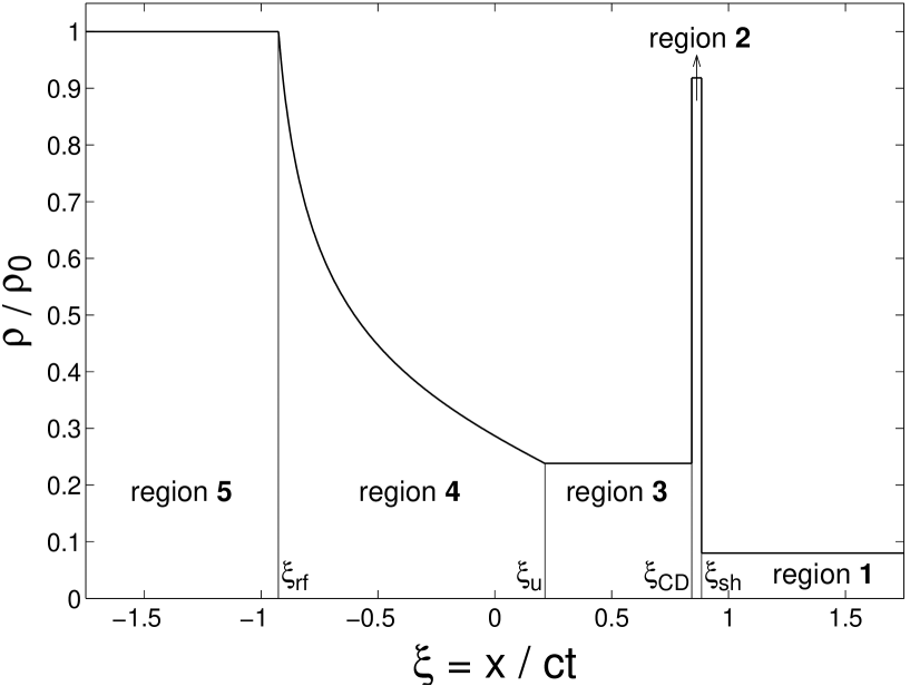
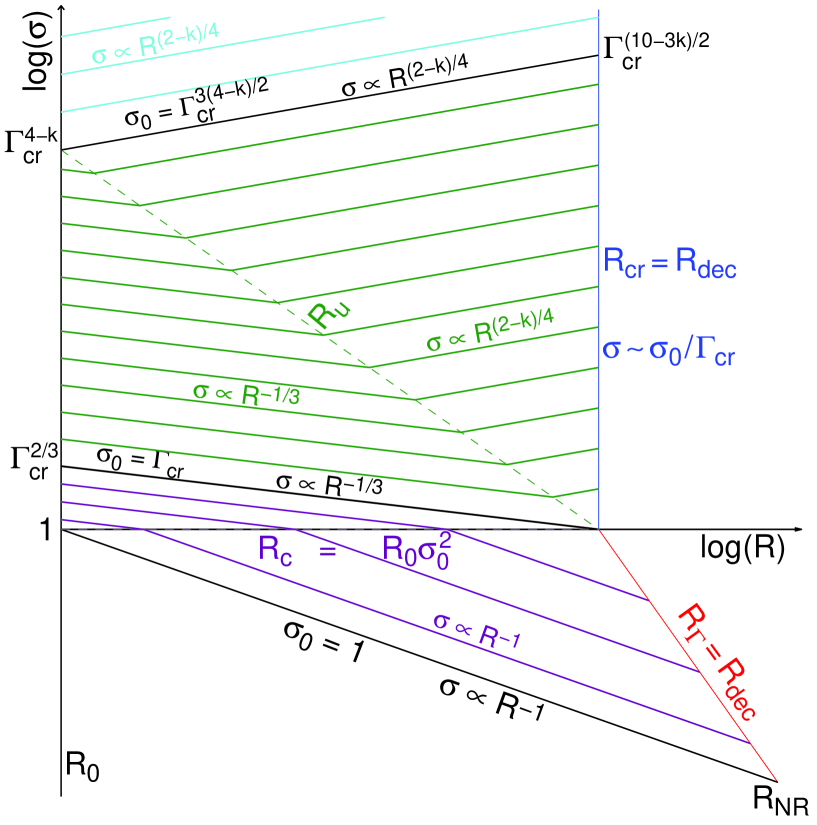
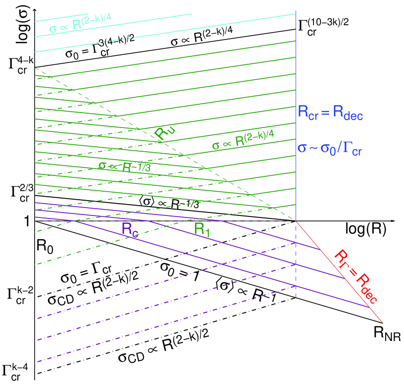
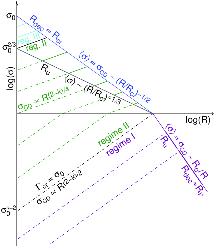
This spherical self-similar solution for is a very useful starting point for the current discussion. It will be described it in terms of the corresponding planar solution, where a uniform region would correspond to an dependence of the density or magnetic pressure in the spherical solution. We are interested in an initially highly magnetized flow (), and for all cases of interest (except regime IV, which is described separately in § 4.5) the shock that is driven into the external medium is (at least initially) highly relativistic, the shock front moving with . The planar Riemann problem contains 5 regions (see Fig. 1): (1) at , where and at the location of the shock front, there is cold, unmagnetized, unperturbed uniform external medium at rest with rest mass density , (2) at there is a uniform999As discussed above, in this region there is a deviation from the simple scaling between the planar and spherical cases, and the BM76 solution with and holds there in the spherical case. region of shocked external medium, moving at with , where at there is a contact discontinuity (CD), (3) at there is a uniform region (moving at with ) occupied by magnetized material (originating from region 5, or from the original magnetized outflow in an astrophysical context) that has passed through a rarefaction wave (region 4) and is accumulating between the front end of the rarefaction wave, at101010Here is the dimensionless fast magnetosonic speed within the rarefaction wave (region 4), at the point where the flow velocity is . , and the CD, (4) at is a region with a rarefaction wave described by the self-similar solution in Appendix A of paper I, where is its tail, and (5) at is the original unperturbed uniform, cold magnetized shell at rest with rest mass density , magnetic field , and magnetization .
Now, let us consider such an initial shell of finite initial width , whose back end is leaning against a conducting “wall” (at ). At (where for ) the tail of the leftward moving rarefaction wave reaches the wall and a secondary right-going rarefaction wave forms that decelerates the material at the back of the flow. The head111111Note that I refer to the rightmost point in the rarefaction wave as its head. In the original rarefaction wave this was at the vacuum interface while for the secondary rarefaction wave this is at the interface with the original rarefaction wave. of the secondary rarefaction wave is located at and moves to the right with a dimensionless speed
| (22) |
where and are given by the self-similar solution for the original expansion (describing a leftward moving rarefaction), since the part of the flow ahead of the secondary (or “reflected”) rarefaction wave () does not “know” about the existence of the “wall”. At this stage region 5 described above no longer exists, and a new region is formed behind the head of the secondary (right-going) rarefaction wave. This new region carries a very small fraction of the total energy as long as the magnetization at its head is large, where , which implies that this rarefaction is strong and significantly decelerates the fluid that passes through it (see paper I for details). Therefore, as long as this condition holds, most of the energy and momentum in the flow, as well as most of the original rest mass of the magnetized shell, remain in a shell of constant width between and .
The value of is determined by pressure balance at the CD. Since both the normalized pressure, , and the fluid velocity are constant in the range (corresponding to regions 2 and 3; see Fig. 1), and so that the external density can be evaluated at either of these radii, , we have
| (23) | |||
| (24) |
where is the normalized density (i.e. in the planar case and in the spherical case) and is its value at , while Eq. (24) holds for .
Although the self-similar solution at is strictly valid only for , for which is constant, we shall make the approximation that it still provides a reasonable description of the flow for , in which case , , etc., gradually evolve with time.
Denoting the initial shell to external density ratio by , Eq. (23) implies
| (25) |
where . For the self-similar rarefaction wave solution in region 4 (see paper I),
| (26) |
where is the local value of the magnetization parameter, and the Riemann invariant approaches a value of for . We are interested primarily in the relativistic part of region 4, for which is given by121212The result for the bulk of the rarefaction wave (where and ) can be understood considering a finite shell of initial width and energy (per unit area) . After the passage of the rarefaction wave, the shell width becomes , and since it is relativistic there is an electric field in the lab frame that is almost equal to the magnetic field so that the shell energy is . Now, requires , and since , implying . More generally, , where .
| (27) |
At the Lorentz factor varies significantly with as , while for it approaches a constant value of . The transition between these two regimes occurs at for which [though , and ]. We are particularly interested in when this also corresponds to the transition between regions 4 and 3, i.e. and , which according to Eq. (25) corresponds to , or to a radius that can be defined by and is given by
| (28) |
For both and do not change with radius, so that generally is either always below 1 or always above 1, corresponding, respectively, to regimes I and II that are discussed below, so that in this case there is no radius where .
If the magnetization in region 3 or just behind the CD is low, , then according to Eq. (27), so that Eq. (25) implies
| (29) |
If, on the other hand, the magnetization in region 3 or just behind the CD is high, , then Eq. (27) implies (since in all of the region behind the CD), and in particular , so that Eq. (25) gives
| (30) |
where is the radius at which reaches the value when , and an expression for this radius is provided in Eq. (46) below.
4.2 Regime I
From the derivation above it becomes clear that for the external medium would hardly affect the acceleration phase, and the magnetized shell would accelerate essentially as if it were expanding into vacuum (as described in paper I, and summarized in § 3). This can be seen from the fact that this condition corresponds to , i.e. that even by the coasting radius the region of the original shell that had been affected by the external medium (region 3) occupies only a small part of the flow near its head that carries a small fraction of its energy. The transition, where , corresponds to the equality of the coasting radius (or distance), , and the deceleration radius131313The deceleration radius is the radius at which most of the energy is transferred to the shocked swept-up external medium. Here its post-shock Lorentz factor is and therefore the energy given to a swept-up external rest mass is , and is given by .. In planar symmetry with a constant external density (which corresponds to in spherical symmetry), conservation of energy implies and thus the deceleration distance is given by (where for simplicity we discard factors of order unity) so that indeed corresponds to , as it should. For spherical symmetry, energy conservation reads , implying a deceleration radius , so that indeed corresponds to or . Note that in this regime essentially corresponds to that is given in Eq. (5) where is replaced by .
For , increases with radius (see Eq. [29]) and since we have seen that regime I corresponds to this implies that all along. For , on the other hand, decreases with radius passing through the value of 1 at a radius given by . This would be physically interesting only if , which corresponds to . In this parameter regime , so that Eqs. (29) and (30) imply that at while at (or at , as we shall see later). For both and we have at .
One can find the time when the reflected rarefaction wave reaches region 3, , or the corresponding radius . Relying on the derivations in paper I, one obtains , which upon substitution of from Eq. (29) and solving for gives
| (31) |
where (discussed below) is the radius where a strong reverse shock develops. Therefore, clearly , and the reflected rarefaction reaches region 3 well before a strong reverse shock develops. The rarefaction wave also reaches the CD ( at a radius ) within a single dynamical time from reaching (i.e. ),
| (32) |
where and the last approximate equality is valid since . Once the right-going rarefaction wave reaches the CD, this triggers a gradual deceleration of the CD, which is initially weak as the rarefaction is weak at this stage since .
In regime I, which corresponds to or , there are three main stages in the dynamics of the shell (see Figs. 2 through 7): (i) initially (at ) the shell accelerates, its typical Lorentz factor increasing as while its typical magnetization decreases as (since magnetic energy is converted into kinetic energy while the total energy is conserved, ), (ii) at the coasting radius, , the kinetic energy becomes comparable to the magnetic energy, , so that at most of the energy is already in kinetic form and the shell coasts at while its magnetization decreases as , (iii) at most of the energy is transfered to the shocked external medium141414At the shocked external medium holds only a small fraction of the total energy, (for for which the forward shock decelerates)., and at the flow approaches the BM76 self-similar solution where . This is summarized in the following equation:
| (33) |
Please note that in regime I, at . However, at as the original magnetized shell becomes part of the BM76 self-similar solution its Lorentz factor is and it decreases with time along with its magnetization and total energy. As long as it is relativistically hot and thus part of the BM76 solution, its Lorentz factor scales as while its magnetization decreases as , where is the time when radiation from the original magnetized shell reaches the observer. However, since the reverse shock is only mildly relativistic the shell’s temperature quickly becomes sub-relativistic and it deviates from the BM76 solution (and the corresponding scalings above), decelerating more slowly (Kobayashi & Sari, 2000).
In regime I, the typical magnetic pressure in the ejecta shell at is (where is its typical or average proper density), while the pressure of the shocked external medium is , so that the typical or average magnetic pressure in the shell is much larger, . However, at larger radii the two pressure scale as and so that their ratio drops with radius as and the two pressures become comparable at , where
| (34) |
A strong reverse shock must form at , since at that stage the magnetic pressure can no longer balance the thermal pressure of the shocked external medium at the CD, and a new source of pressure is needed, which comes in the form of thermal pressure that is generated by the reverse shock that develops and soon becomes dominant. While a weak reverse shock might develop earlier, at the thermal pressure it generates would be much smaller than the magnetic pressure, so that it would not have a significant effect on the dynamics and would dissipate only a small fraction of the total energy. The reverse shock is initially Newtonian, until it becomes mildly relativistic at . This can be seen by balancing the pressure behind the forward shock, , with the (predominantly thermal at ) pressure behind the reverse shock, , which implies a reverse shock upstream to downstream relative 4-velocity of .
This is the familiar “thin shell” case for the deceleration of an unmagnetized initially coasting shell (described in § 2). The shell starts spreading significantly (in the lab frame) at , resulting in the formation of a reverse shock that becomes thermal pressure dominated around , and gradually strengthens until it becomes mildly relativistic near its shell crossing radius, which is the deceleration radius, . Near , where most of the energy is given to the shocked external medium, and where the reverse shock crosses most of the shell, the typical magnetization of the shell is low, (where I have identified in Eq. [11] with ). Note that this regime corresponds to , which can also be expressed as where in the expression for (Eq. [8]) one substitutes and , thus clearly corresponding to the unmagnetized (or low magnetization) thin shell case. A larger magnetic field downstream (and also somewhat upstream) of the reverse shock is possible due to magnetic field amplification in the reverse shock itself, which may allow for a reasonable radiative efficiency coupled to the rather effective energy dissipation in the mildly relativistic reverse shock.
4.3 Regime II
This regime corresponds to , where the condition corresponds to . As we shall see below, this also implies that and .
For , increases with radius, and since in regime II it is larger than 1 at , it passes through the value of 1 at a smaller radius that is given by , and the ordering of the critical radii is . As in regime I, also here in regime II, is physically interesting only if , which now corresponds to . In this parameter range increases with radius as at and as at . For we have , and all along. Altogether, for we have at and as at . For , on the other hand, so that and all along.
For we have a self-similar solution for the rarefaction wave, thanks to the equivalence of the cold MHD equations for a spherical flow to those for a planar flow, which make it easier to explicitly calculate much of the relevant dynamics. For a general value of we do not have this privilege, and I have relied on the approximation that this self-similar solution still approximately holds in this case where and gradually change with time. In order to further justify this, I now provide an alternative derivation of Eq. (30). The pressure balance at the CD reads , implying
| (36) |
where is the instantaneous Poynting flux through a static spherical surface at . Note that is close to the mean (isotropic equivalent) luminosity (or power) of the source, [identifying the initial width of the shell with its initial radius , where the shell initially occupies the region , while and ], only where the magnetization parameter just before the CD is large, , which corresponds to . In this case and we have
| (37) |
| (38) |
This is valid as long as the value of the lab-frame magnetic field at the CD (i.e. the head of the outflow) is close to its original value, i.e. for , which holds at .
The condition that in regime II implies that , and therefore at region 4 (see Fig. 1) holds most of the volume and energy, and at . At this stage the typical or mean value (weighted average over the energy in the lab frame) of the Lorentz factor within the magnetized shell, , increases with time, while for the Lorentz factor of the uniform region at its front, , remains constant. More generally, is given by the smaller between the expression in Eq. (37) and . This acceleration (increase in ) lasts until the secondary (or reflected) rarefaction wave finishes crossing region 4, i.e. until equals
| (39) |
(where since , we have and specifically ), at , which corresponds to
| (40) |
This implies
| (41) |
which is different from the result for regime I (see Eq. [31]), where .
At this stage ( or ) most of the energy in the flow is in151515This can be seen as follows for . The pressure is continuous across the CD, and therefore the energy density of regions 2 and 3 in the lab frame is similar, and their relative energy is determined by their relative width in the lab frame. For region 2, using the uniform velocity approximation (for the BM76 solution , which is rather similar), while for region 3, , and therefore the width of region 3, , is larger than that of region 2, , by a factor of , since in this regime. region 3, which moves with given by Eq. (37), that represents at this stage (). Region 3 is gradually crossed by the right going rarefaction wave, until it reaches the CD at (as shown in detail below), which marks the end of this stage. At that point most of the energy is in the shocked external medium161616At only a small fraction of the total energy is in the shocked external medium, ., and the flow approaches the BM76 self-similar solution (first the rarefaction wave crosses region 2, within a few dynamical times,171717For , making the approximation that the region between the CD and shock front has the constant velocity of the CD and that and using Eq. (21) one obtains that during the time the rarefaction wave travels from the CD to the shock front the radius increases by a factor of . If we self-consistently use the above assumption to estimate the width of this region (even though this is not fully self-consistent) this gives instead of Eq. (21), and a growth in radius during the rarefaction crossing by a factor of . In both cases it is close to a factor of . This factor is relatively large since the sound speed in region 2 in “only” (as it is unmagnetized but relativistically hot, while regions 3 and 4 are cold but highly magnetized) and the shock front moves somewhat faster than the fluid in region 2. and then the adiabatic BM76 self-similar solution is quickly approached).
The width of region 3 at (when the rarefaction wave reaches ) in the lab frame is . In region 3,
| (42) |
so that and therefore and the increase in radius, (or time, ), during the time it takes the rarefaction wave to cross region 3 is for , while more generally
| (43) |
so that the rarefaction reaches the CD at .
The deceleration radius in this regime can be obtained by equating the initial magnetic energy to the energy of the swept-up external medium, , which implies
| (44) |
and therefore where is the radius at which , and
| (45) |
is the typical Lorentz factor during the subsequent constant energy self-similar (BM76) stage. Estimating the value of from Eqs. (37) and (45) and identifying with gives,
| (46) |
or
| (47) |
During the initial acceleration (at ), . This lasts until most of the energy is transfered to the part of the magnetized shell with , which occurs at a radius , Lorentz factor , and magnetization given by
| (48) |
Moreover,
| (49) |
so that near the transition to regime I, and .
In Regime II we have , which corresponds to (i.e. ), and . The different critical radii are related by
| (50) |
so that for or for and we have and is irrelevant (as all along), while for and we have and is relevant. In all cases is not relevant physically (since it looses its meaning as a coasting radius).
The typical magnetization of the shell in the intermediate stage is
| (51) |
so that at we have . Thus, altogether in regimes I and II we have
| (52) |
while in regime II we have
| (53) |
| (54) |
| (55) |
| (56) |
4.4 Regime III
In regime II we had so that the plasma near the CD was super-fast-magnetosonic with respect to the “wall” already at , with , and thus not in causal contact with the source. Here, in regime III, we consider what happens when . In all the regions behind the CD, the fast magnetosonic Lorentz factor is given by , so that as long as the flow remains in causal contact with the “wall” or central source, . Thus, the flow remains roughly uniform and the conditions just behind the CD are representative of the typical values in the shell, , implying
| (57) | |||||
| (58) |
so that the conditions near are very similar to those in regime II: , , , and . This implies that regime III, defined above through the condition , corresponds to , or .
In this regime is still given by Eq. (36) while
| (59) |
so that region 3 initially occupies most of the volume, . This demonstrates again that already at the conditions just behind the CD (region 3) dominate the average values over the original magnetized shell, so that and are given by Eqs. (37) and (38), respectively. Region 4 occupies only a small fraction of the total volume already at , , and it is very quickly crossed by the right-going rarefaction wave, which reaches region 3 () at (and ) that corresponds to
| (60) |
This implies that and the time since when the right-going rarefaction wave reaches the CD () is dominated by its propagation time through region 3. For ,
| (61) |
so that it reaches the CD at a radius . Similarly, since in this case then for a general -value Eq. (43) implies , so that again, .
The effect of the external medium in this regime is very large, in the sense that it causes most of the energy to be in the uniform region 3, with a sub-fast-magnetosonic speed relative to the “wall”. Nevertheless, since this region is still relativistic, it takes the rarefaction wave that is reflected from the wall a long time to cross this region in the lab (or wall) frame, and this occurs at a large distance from the wall, , near the deceleration radius where most of the energy is transferred to the shocked external medium. Altogether, in regime III we have (see Table 2), and similar regime II, here as well does not have a physical significance (and the same also holds for , since we always have in regime III).
In regime III, becomes independent of while scales linearly with , when fixing , , and (which fixes ) while letting and vary (since we have , so that fixing implies that ). Such a variation of the parameters means fixing the overall properties of the flow and changing only its composition or magnetization (as is done in Figs. 2 through 7). In this regime the global dynamics become insensitive to the exact composition. This can be thought of as the high magnetization limit, where the behavior of the outflow approaches that of an electromagnetic wave that is emitted at the source and reflected by the CD, where the time when the back end of the finite wave reflects off the CD corresponds to the time when the right-going rarefaction wave reaches the CD, .
Alternatively, as is done in Figs. 8 and 9, one could fix the properties of the magnetized flow: , , , (and thus also ) and vary the normalization of the external density: or (while fixing its power-law index, ), which effectively varies and . It can be seen from Figs. 8 and 9 that as the external density goes to zero we have , and , and this the solution approaches that of expansion into vacuum (or the extreme limit of regime I). As the external density increases , and all decrease, until when , and there is a transition to regime II. As the external density increases even further a transition to regime III occurs when , and . Finally, when the external density becomes so large that , , and , the flow remains Newtonian and there is a transition to regime IV that is discussed below.
4.5 Regime IV
For a sufficiently large external density, , the formal expression for gives and the flow remains Newtonian. If we consider a source that is active over a time then when the central source finishes ejecting the highly magnetized outflow, it would be bounded within , where I neglect factors of order unity for simplicity (here is still defined through the relation , even though it loses its physical meaning from the relativistic regime). More generally, at the radius of the CD satisfies . For a tangential magnetic field, which scales as , the magnetic pressure at , , would be balanced by the ram pressure of the shocked external medium at the frame of the CD, , leading to
| (62) |
This implies , which demonstrates self-consistency by showing that the flow is indeed Newtonian in this regime. The magnetic energy in the original outflow, at , is given by , where and are the injected luminosity and corresponding energy over a time for a relativistic outflow. This would violate conservation of energy, if the outflow emanating from the central source was indeed relativistic (this is basically the well-known -problem).181818For a steady central source that ejects a magnetized outflow over a finite time this regime resorts back to the well known problem, where in ideal MHD the stored magnetic energy grows quadratically with the injection time of the central source, while the actual injected energy grows only linearly with this time, implying a breakdown of one or more of the underlying assumptions. This may be relevant, e.g., for a millisecond magnetar born inside a collapsing massive star, as a possible progenitor of long duration GRBs. However, since in this regime the outflow is sub-sonic (or sub-fast-magnetosonic) and Newtonian, the information about the existence of the external medium must propagate back to the source producing a back reaction that results in a Newtonian outflow with a speed . For such a Newtonian magnetized outflow the electromagnetic luminosity is , and for this gives and , which is consistent with the above estimate. Even during the initial injection phase () the shocked external medium holds a good fraction of the total energy at any given time. After the injection stops, at , most of the energy is quickly transfered to the shocked external medium on the dynamical time (up to or so), and the flow settles into an adiabatic Sedov-Taylor solution with velocity , radius and energy .
If we start with a magnetized spherical shell or “ball” of radius , initially at rest, then in this case the magnetic pressure at is and equating it to the ram pressure of the shocked external medium, , implies . Therefore, it would significantly increase its radius and transfer most of its energy to the shocked external medium on its dynamical time, which corresponds to a timescale of
| (63) |
At most of the energy is in the shocked external medium and the flow settles into an adiabatic Sedov-Taylor solution with velocity , radius and energy .
4.6 Regime II∗ ():
When the external density drops very sharply with radius, , then initially grows with radius faster than , which has interesting implications. Regime II that exists for disappears for and reappears for in a different form that we shall call regime II∗, which corresponds to . For , Regime I holds for and regime III holds for .
In regime I, for there in no (as and all along) and the shocked external medium decouples from the magnetized shell at a decoupling radius of , as the forward shock accelerates down the steep external density gradient, and the shocked external medium carries only a very small fraction of the total energy, . In the parameter range , on the other hand, there is a radius where and the ordering of the critical radii is , so that following Eq. (51) until and at , and the decoupling of the forward shock from the magnetized shell occurs at . In both cases at the shell accelerates in the wake of the accelerating forward shock, almost as if into vacuum. At it starts coasting and spreading radially, where it can in principle keep coasting indefinitely (or more realistically until the assumption of a very steep external density profile breaks down, and enough external mass is swept-up that could decelerate the forward shock and, in turn, also the shell).
In regime II∗ the ordering of the critical radii is (see Table 3). Initially, at , the typical Lorentz factor and magnetization are similar to those at the CD and are determined by the pressure balance at the CD, following Eqs. (37) and (51). At the bulk of the shell decouples from the CD and accelerates as until reaching the coasting radius (where it starts to coast and spread, as in regime I), while keeps following Eq. (51) until and at . At we have and , while the shocked external medium decouples from the shell, carrying with it only a small fraction of the total energy, , as it keeps accelerating down the steep external density gradient, with (where the same energy is given to a decreasing amount of newly swept-up external rest mass). The original shell keeps coasting and spreading radially in the evacuated region in the wake of the accelerating forward shock, essentially as if into vacuum. Near the transition to regime III we have and therefore , so that the energy in the shocked external medium becomes comparable to the total energy.
In regime III the ordering of the critical radii is , and there are no or . At the shell accelerates as following Eq. (51), where the typical values of and are close to those at the CD. The shocked external medium decouples from the original magnetized shell at , but since in this case the rarefaction wave is still strong when it reaches so that it effectively decelerates the shell and very little energy remains in the original shell at later times (or larger radii), while most of the energy is transfered to the shocked external medium, which approaches the BM76 self-similar solution.
4.7 Summary
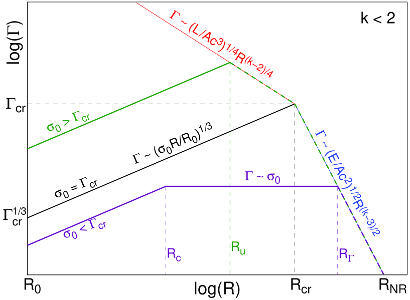
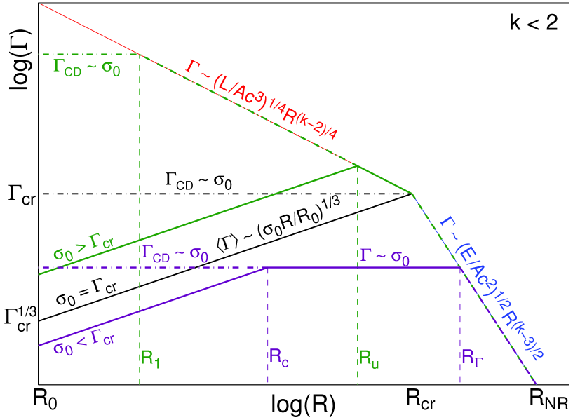
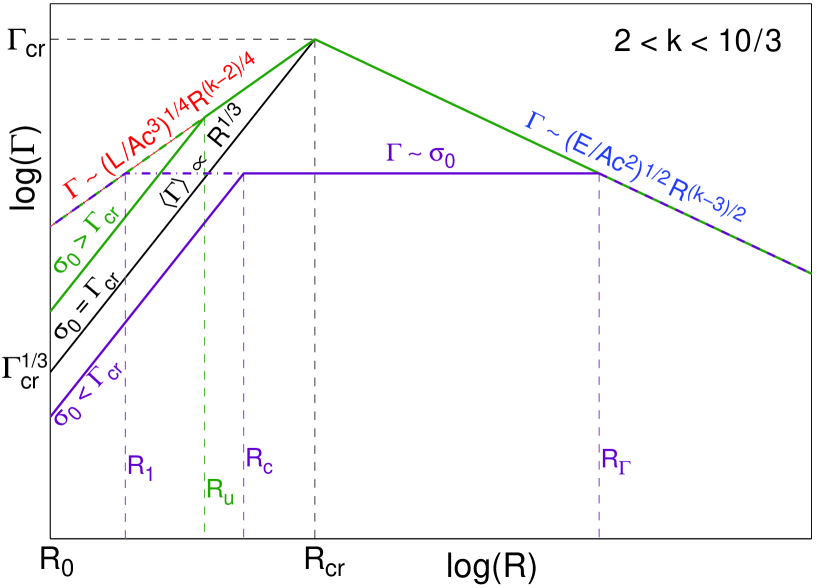
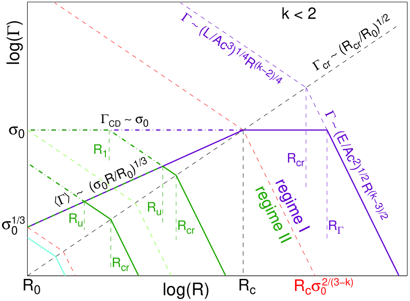
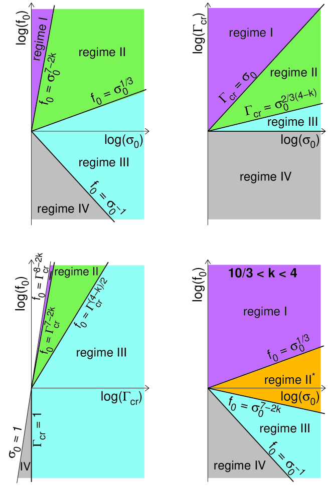
The different regimes are summarized in Tables 2 and 3 as well as in Figure 10. Tables 2 and 3 provide the ordering of the various critical radii in the different regimes, along with the parameter range occupied by each regime, in terms of the initial shell to external medium density ratio , initial magnetization , and . Figure 10 shows the regions of parameter space occupied by each regime within the two dimensional planes spanned by – (top left panel for and bottom right panel for ), – (top right panel for ), – plane (bottom left panel for ).
In order to gain some intuition for these results and better understand them, it is useful to follow the behaviour of the system when varying one key physical parameter and leaving the others fixed. First, I vary the initial magnetization (and for consistency) while keeping fixed the energy ( or ), initial time or length scale ( or ) and external density ( and or ), and thus also and . This corresponds to a constant and varying , or in Figure 10 to a horizontal line in the top right panel, a vertical line in the bottom left panel, and a diagonal line parallel to the line separating regimes III and IV in the remaining two panels (showing the – plane). The behaviour in this case is summarized in Figures. 2 through 7.
In regime I () the acceleration is almost as if into vacuum: and until most of the energy is converted to kinetic form at the coasting radius , where and . Then the shell starts coasting (at ) and its width in the lab frame starts growing linearly with radius resulting in a fast drop in its magnetization, . At this regime reverts back to the well-studied unmagnetized “thin shell” case, with a reasonable spread in its Lorentz factor, . A reverse shock develops and is initially Newtonian, but strengthens as the shell widens, until it becomes mildly relativistic when it finishes crossing the shell at the deceleration radius, , where the magnetization is low, .
In regime II () the initial acceleration of is limited by the external medium at , where most of the energy is still in magnetic form (), and thus there is no coasting phase. Between and the typical Lorentz and magnetization of the shell are similar to those just behind the CD and determined by the pressure balance at the CD, . A rarefaction wave gradually crosses the shell from its back to its front, until reaching the CD at . At that point the shocked external medium starts dominating the total energy and the flow approaches the BM76 self-similar solution.
In regime III () the external density is large enough that there is no impulsive acceleration stage with . Instead, the pressure balance at the CD determines the shell’s typical Lorentz factor and magnetization from the very start, at , and the dynamics become insensitive to the exact composition [i.e. to the value of , when fixing the external density ( and ) and the shell luminosity () and initial width ()]. This is the high- limit where the flow behaves like an electromagnetic wave that is emitted at the source and reflected at the CD.
There are also more “exotic” regimes, such as regime IV where the external density is so high that flow remains Newtonian, or regime II∗ that exists only for a highly stratified external density () where the external shock accelerates down the steep external density gradient and decouples from the original shell, carrying a small fraction of the total energy, while the original shell travels in its wake essentially as if into vacuum, similar to regime I. Note that regime IV corresponds to and thus cannot be reached when fixing to a value larger than 1 and varying .
A slightly different way to gain perspective about these results is by varying the external density normalization ( or or ) while keeping the other parameters fixed (, , , , and therefore also and ). In this case remains constant while and vary, where both and decrease when the external density increases. In Figure 10 this corresponds to a vertical line in all but the bottom left panel, where it corresponds to a slightly diagonal line parallel to the line (the left boundary of the colored regions). The behavior in this case is illustrated in Figures 8 and 9. For a sufficiently low external density, corresponding to or we are in regime I, where the expansion is initially essentially as if into vacuum, reaching the coasting radius at that is independent of and decelerating significantly only at . As the external density increases, decreases, bringing about first regime II ( or ), and at even larger external densities regime III ( or ). For the highest external densities (, or ) the flow remains Newtonian all along (regime IV).
5 Comparison with Previous Works
The unmagnetized case for the deceleration of a finite uniform relativistic shell by the external medium has been studied in the context of GRBs (Sari & Piran, 1995; Sari, 1997; Kobayashi & Sari, 2000; Kobayashi & Zhang, 2003; Nakar & Piran, 2004). The main results have been summarized in § 2 and extended to a general power-law of the external density profile, and are consistent with the previous results. The deceleration of a magnetized relativistic shell by an unmagnetized external medium has also been studied (Zhang & Kobayashi, 2005; Giannios, Mimica & Aloy, 2008; Mimica, Giannios & Aloy, 2009; Mizuno et al., 2009; Levinson, 2010; Lyutikov, 2011).
Zhang & Kobayashi (2005, hereafter ZK05) have both considered arbitrary “initial” values for the shell Lorentz factor and magnetization, and have attached too much importance to the crossing of the shell by the reverse shock, while for even if a reverse shock exists its effect on the global dynamics of the system is very small (it dissipates only a small fraction of the total energy, of the order of , and by its shell crossing time only a similarly small fraction of the total energy is transfered to the shocked external medium). Therefore, the conclusions of that paper are very different from my results.
Giannios, Mimica & Aloy (2008) have considered a similar initial setting and argued for a different condition for the formation of a reverse shock191919Their argument that the shell can be crossed by a fast-magnetosonic wave (and thus come into causal contact) faster than by a fast-magnetosonic shock (both starting at the CD) appears to contradict the basic notion that a shock must always travel faster than the relevant corresponding wave. It arises since they use the formula for the radius at which the reverse shock crosses the shell from Eq. (38) of ZK05 that is valid only for a strong reverse shock (with a relativistic upstream to downstream 4-velocity, , or in the notation of ZK05) also outside its range of applicability, while the result for a fast-magnetosonic wave is approached in the opposite limit of a weak reverse shock ( or ).. While the condition for the formation of a reverse shock in the ideal Riemann problem addressed in ZK05 is correct, such initial conditions are not realistic and the formation of a reverse shock and its properties can be sensitive to the exact initial conditions or to fluctuations in the external density, etc. Moreover, in the high- limit even if such a shock exists it has a very small effect on the global dynamics, which are the main focus of the present work, and therefore this is not addressed here in detail. In Mimica, Giannios & Aloy (2009) the problem is addressed with a similar initial setup but using high resolution 1D RMHD numerical simulations. There, the regime that is argued to have no reverse shock in Giannios, Mimica & Aloy (2008) is correctly found to have either a weak or no reverse shock. They also demonstrate numerically that the flow quickly approaches the BM76 self-similar solution after the deceleration radius.
Mizuno et al. (2009) point out that for the Riemann problem of a magnetized shell moving relativistically relative to an unmagnetized region (or “external medium”) at rest, above some critical value of magnetization parameter there is a rarefaction wave that propagates into the magnetized shell and accelerates it, and only below that critical value there is a (reverse) shock that decelerates the shell. While this observation is correct, this Riemann problem is not a realistic setup for the deceleration of magnetized GRB ejecta, since it uses arbitrary “initial” conditions near the deceleration radius. Lyutikov (2011) has analyzed the similar problem of the deceleration of a shell with arbitrary initial Lorentz factor and magnetization, concluding that the differences between the magnetized and unmagnetized cases are rather small, and involve mainly the existence or strength of the reverse shock at early times (which may be non-existent or weak for high magnetizations), rather than the global gross properties of the flow. I find that this is a right answer for the wrong question, in the sense that the initial setup is too arbitrary to realistically apply to GRB outflows. The impulsive acceleration process determines the conditions near the deceleration radius, which are therefore not arbitrary, and some regions of parameter space and their corresponding dynamical regimes cannot be realized under realistic circumstances.
Paper I has addressed mainly the impulsive acceleration into vacuum of a highly magnetized shell, starting at rest. However, at the end of its subsection 5.2 it also briefly addressed the expansion of such a shell into an unmagnetized external medium. There it has outlined the two main dynamical regimes, which in the current work are referred to as regimes I and II. Levinson (2010) has also considered the acceleration and of an impulsive magnetized shell and its deceleration due to the interaction with the external medium, following paper I and treating the latter part in more detail. Levinson (2010) also identified regimes I and II. His expressions for the maximal Lorentz factor of the shell in regime II are only a factor of 1.09 lower than Eq. (11) of the current work for , and a factor of 1.57 lower for (the latter difference might appear larger since he used , and for his fiducial values while the current work uses , and ). The current work finds that for the maximal value of is obtained at , and is a factor of (see Eq. [49]) larger than . However, for the values of and considered by Levinson (2010) this factor if for , and thus consistent with his results (see his Fig. 5).
Levinson (2010) has argued, however, that multiple sub-shells with an initial separation comparable to their initial width would collide and merge while still highly magnetized, which is incorrect and in contradiction with paper I. An accompanying paper (Granot, 2011) focuses on the possible role of multiple sub-shells, which can alleviate some of the requirements on the Lorentz factor of the outflow and may help accommodate GRB observations much better.
6 Discussion and Conclusions
This work has presented a detailed and unified treatment of the magnetic acceleration of an impulsive, initially highly magnetized () shell and its deceleration by an unmagnetized external medium (with a power-law density profile). The dynamics divide into three main regimes (I, II, and III) and two more “exotic” regimes (relevant for an external density that either sharply drops with radius [II∗], or is very large [IV], leading to a Newtonian flow).
In regime I the external density is low enough that the shell accelerates almost as if into vacuum. At the coasting radius, , it reaches its maximal Lorentz factor of (where is given in Eq. [11]) and becomes kinetic energy dominated. At this regime reverts back to the well-studied unmagnetized “thin shell” case (Sari & Piran, 1995), where the shell coasts and spreads radially, , as its magnetization rapidly decreases well below unity, . In this regime the reverse shock is initially Newtonian, starts dominating the pressure behind the CD at , and becomes mildly relativistic when it finishes crossing the shell, at . The deceleration radius, , which corresponds to an observed deceleration time , is where most of the energy dissipation in the shell takes place and most of the energy is transfered to the shocked external medium. Thus, both the reverse shock emission and the afterglow emission are expected to peak on the timescale of . At (or ) the flow quickly approaches the BM76 self-similar solution, which for GRBs signals the start of the usual long-lived decaying afterglow emission. The magnetization at the deceleration radius is low, . If it is very low then magnetic field amplification in the mildly relativistic collisionless (reverse) shock that develops could bring the downstream magnetic field to within a few percent of equipartition, thus allowing a good radiative efficiency for synchrotron emission, resulting in a bright reverse shock emission. In this regime the reverse shock emission and the afterglow emission both peak on a timescale that is larger than the duration of the prompt GRB emission, . Moreover, the degree of magnetization behind the reverse shock, , can be directly inferred from the ratio of these two observable times.
In regimes II or III the shell remains highly magnetized near the deceleration radius, , which strongly suppresses the reverse shock (which either becomes very weak or non-existent) and its associated emission. The energy in the flow is transfered to the shocked external medium (mostly near ) with very little dissipation within the original shell as long as ideal MHD holds. This is a highly magnetized “thick shell” case, and the afterglow onset time is similar to the initial shell light crossing time, . For a single shell ejected from the source the prompt emission in this case might either arise from the onset of the forward shock emission (for an external shock origin, which makes it difficult to account for significant variability, and in which case ) or alternatively due to magnetic reconnection events within the highly magnetized shell. The latter might be induced by the deceleration of the shell due to the external medium, in which case they might peak near , since the angular size of causally connected regions () grows as the shell decelerates ( decreases with radius for ) and at most of the energy is still in the original magnetized shell (this would again lead to ).
For the single shell case that was analyzed in this work there is either the low magnetization “thin shell” (regime I) or the high magnetization “thick shell” (regimes II or III). There is no low magnetization “thick shell” case where a strong highly relativistic reverse shock develops, which can result in a bright reverse shock emission on a timescale comparable to that of the prompt gamma-ray emission in GRBs (). Similarly, there is no high magnetization “thin shell” case where the reverse shock is severely suppressed by a high magnetization in the shell near the deceleration radius and the afterglow onset occurs well after the prompt GRB emission (). Therefore, a bright reverse shock emission is possible only in the low magnetization “thin shell” case – regime I, in which case this reverse shock emission (as well as the afterglow emission) would peak on a timescale larger than the duration of the prompt GRB emission, . An accompanying paper (Granot, 2011), however, shows that if the flow consists of many distinct sub-shells instead of a single shell, then this may also allow a low magnetization “thick shell” regime.
The Lorentz factor of the emitting region in GRBs must be high enough to overcome the compactness problem and avoid excessive pair production within the source (Krolik & Pier, 1991; Fenimore et al., 1993; Woods & Loeb, 1995; Baring & Harding, 1997; Lithwick & Sari, 2001). It had been recently argued (Levinson, 2010) that the interaction with the external medium might not enable an impulsive highly magnetized outflow in GRBs to accelerate up to sufficiently high Lorentz factors, and that its maximal achievable Lorentz factor is largely limited to . This would pose a particularly severe problem for a stellar wind-like external medium () for which typically (see Eq. [11]). Recent high-energy observations by the Fermi Large Area Telescope (LAT) have set a lower limit of for the emitting region in a number of GRBs with a bright high-energy emission (Abdo et al., 2009a, b; Ackermann et al., 2010) using a simplified one-zone model. However, a more detailed and realistic treatment shows that the limit is lower by a factor of (Granot et al., 2008; Ackermann et al., 2011; Hascoët et al., 2011), which would correspond to for the brightest Fermi LAT GRBs. Nevertheless, this might still pose a problem for a single highly magnetized shell in a stellar-wind environment.
Regime I implies a maximal Lorentz factor of the flow, (where is given in Eq. [11]). In regime II, a higher maximal Lorentz factor is possible for , and peaks at where it exceeds by a factor of (see Eq. [49]), while can reach values as high as at (however, the material with such a Lorentz factor would carry only a small fraction of the total energy, at ). In regime III the typical Lorentz factor is close to that of the CD, , and for they both peak at where they exceed by a factor of , while at . All this could help increase above for . However, for a stellar wind-like (or steeper) external medium, (or ), we have , which makes it very difficult to satisfy the observational constraints on from pair opacity (mentioned above), and to a lesser extent also those from the onset time of the afterglow emission (usually around a few hundred; Sari & Piran, 1999; Nakar & Piran, 2005; Molinari et al., 2007; Zou & Piran, 2010; Gruber et al., 2011). The accompanying paper (Granot, 2011) shows, however, that if instead of a single shell the flow is initially divided into multiple, well separated sub-shells, then it can reach and reasonably efficient internal shocks can naturally take place at such high Lorentz factors. This greatly helps to satisfy the observational constraints on .
References
- Abdo et al. (2009a) Abdo, A. A., et al. 2009a, Science, 323, 1688
- Abdo et al. (2009b) Abdo, A. A., et al. 2009b, ApJ, 706, L138
- Ackermann et al. (2010) M. Ackermann et al. 2010, ApJ, 716, 1178
- Ackermann et al. (2011) M. Ackermann et al. 2011, ApJ, 716, 1178
- Baring & Harding (1997) Baring, M. G., & Harding, A. K. 1997, ApJ, 491, 663
- Blandford & McKee (1976) Blandford, R. D., & McKee, C. F. 1976, Phys. Fluids, 19, 1130
- Contopoulos (1995) Contopoulos, J., 1995, ApJ, 450, 616
- Duncan & Thompson (1992) Duncan, R. C.. & Thompson, C. 1992, ApJ, 392, L9
- Drenkhahn & Spruit (2002) Drenkhahn, G., & Spruit, H. C. 2002, A&A, 391, 1141
- Fenimore et al. (1993) Fenimore, E. E., Epstein, R. I., & Ho, C. 1993, A&AS, 97, 59
- Ghisellini (2011) Ghisellini, G. 2011, in “High Energy Phenomena in Relativistic Outflows”, Eds. J.M. Paredes, M. Ribo, F.A. Aharonian, & G.E. Romero (arXiv:1109.0015)
- Giacomazzo & Rezzolla (2006) Giacomazzo, B. & Rezzolla, L. 2006, J. Fluid Mech. 562, 223
- Giannios (2008) Giannios, D. 2008, A&A, 480, 305
- Giannios & Spruit (2006) Giannios, D., & Spruit, H. C. 2006, A&A, 450, 887
- Giannios, Mimica & Aloy (2008) Giannios, D., Mimica, P., & Aloy, M. A. 2008, A&A, 478, 747
- Goldreich & Julian (1970) Goldreich, P., & Julian, W. H. 1970, ApJ, 160, 971
- Goodman (1986) Goodman, J. 1986, ApJ, 308, L47
- Granot (2011) Granot, J. 2011, submitted to MNRAS (paper II)
- Granot et al. (2008) Granot, J., Cohen-Tanugi, J., & do Couto e Silva, E. 2008, ApJ, 677, 92
- Granot, Komissarov & Spitkovsky (2011) Granot, J., Komissarov, S. S. & Spitkovsky, A. 2011, MNRAS, 411, 1323 (paper I)
- Granot & Kumar (2006) Granot, J., & Kumar, P. 2006, MNRAS, 366, L13
- Granot & Ramirez-Ruiz (2011) Granot, J., & Ramirez-Ruiz, E. 2011, book chapter, to appear in ”Gamma-ray Bursts” (CUP), arXiv:1012.5101
- Grimsrud & Wasserman (1998) Grimsrud, O. M., & Wasserman, I. 1998, MNRAS, 300, 1158
- Gruber et al. (2011) Gruber, D., et al. 2011, A&A, 528, 15
- Hascoët et al. (2011) Hascoët, R., Daigne, F., Mochkovitch, R., & Vennin, V. 2011, preprint (arXiv:1107.5737)
- Heinz & Begelman (2000) Heinz S., & Begelman M. C., 2000, ApJ, 535, 104
- Kluźniak & Ruderman (1998) Kluźniak, W., & Ruderman, M. 1998, ApJ, 505, L113
- Kobayashi & Sari (2000) Kobayashi, S., & Sari, R. 2000, ApJ, 542, 819
- Kobayashi & Zhang (2003) Kobayashi, S., & Zhang, B. 2003, ApJ, 597, 455
- Komisarov (1999) Komisarov, S. S. 1999, MNRAS, 303, 343
- Komissarov et al. (2007) Komissarov S. S., Barkov M. V., Vlahakis N., & Königl A., 2007, MNRAS, 380, 51
- Komissarov et al. (2009) Komissarov S. S., Vlahakis N., Königl A., & Barkov M. V., 2009a, MNRAS, 394, 1182
- Komissarov et al. (2010) Komissarov S. S., Vlahakis N., & Königl A., 2010, MNRAS, 407, 17
- Krolik & Pier (1991) Krolik, J. H., & Pier, E. A. 1991, ApJ, 373, 277
- Levinson (2010) Levinson, A. 2010, ApJ, 720, 1490
- Levinson & Eichler (1993) Levinson, A., & Eichler, D. 1993, ApJ , 418, 386
- Lithwick & Sari (2001) Lithwick, Y., & Sari, R. 2001, ApJ, 555, 540
- Lyubarsky (2009) Lyubarsky, Y. E. 2009, ApJ, 698, 1570
- Lyubarsky (2010a) Lyubarsky, Y. E., 2010a, MNRAS, 402, 353
- Lyubarsky (2010b) Lyubarsky, Y. 2010b, ApJ, 725, L234
- Lyutikov (2006) Lyutikov, M. 2006, New Journal of Physics, 8, 119
- Lyutikov (2010) Lyutikov, M. 2010, PRE, 82, 056305
- Lyutikov (2011) Lyutikov, M. 2011, MNRAS, 411, 422
- Lyutikov & Blandford (2003) Lyutikov, M., & Blandford, R. D. 2003, ArXiv Astrophysics e-prints, astro-ph/0312347
- Marti & Múller (1994) Marti, J. M., & Müller, E. 1994, J. Fluid Mech., 258, 317
- Mészáros (2008) Mészáros, P. 2008, in “Accelerator in the Universe”: Interplay between High Energy Physics and Cosmophysics, AIP Conference Proceedings, 1040, 150
- Mészáros, Laguna & Rees (1993) Mészáros, P., Laguna, P., & Rees, M. J. 1993, ApJ, 415, 181
- Mészáros& Rees (1997) Mészáros, P., & Rees, M. J. 1997, ApJ, 482, L29
- Mimica, Giannios & Aloy (2009) Mimica, P., Giannios, D., & Aloy, M. A. 2009, A&A, 494, 879
- Mizuno et al. (2009) Mizuno, Y., Zhang, B., Giacomazzo, B., Nishikawa, K.-I., Hardee, P. E., Nagataki, S., & Hartmann, D. H. 2009, ApJ, 690, L47
- Molinari et al. (2007) Molinari, E., et al. 2007, A&A, 469, L13
- Nakamura & Shigeyama (2006) Nakamura, K., & Shigeyama, T. 2006, ApJ, 645, 431
- Nakar (2007) Nakar, E. 2007, Phys. Rep., 442, 166
- Nakar & Piran (2004) Nakar, E., & Piran, T. 2004, MNRAS, 353, 647
- Nakar & Piran (2005) Nakar, E., & Piran, T. 2005, ApJ, 619, L147
- Nakar, Piran & Sari (2005) Nakar, E., Piran, T., & Sari, R. 2005, ApJ, 635, 516
- Nousek et al. (2006) Nousek, J. A., et al. 2006, ApJ, 642, 389
- Paczyński (1986) Paczyński, B. 1986, ApJ, 308, L43
- Piran (2005) Piran, T. 2005, Rev. Mod. Phys., 76, 1143
- Piran, Shemi & Narayan (1993) Piran, T., Shemi, A., & Narayan, R. 1993, MNRAS, 263, 861
- Sari (1997) Sari, R. 1997, ApJ, 489, L37
- Sari & Mészáros (2000) Sari, R., & Mészáros, P. 2000, ApJ, 535, L33
- Sari & Piran (1995) Sari, R., & Piran, T. 1995, ApJ, 455, L143
- Sari & Piran (1999) Sari, R., & Piran, T. 1999, ApJ, 517, L109
- Shemi & Piran (1990) Shemi, A., & Piran, T. 1990, ApJ, 365, L55
- Tchekhovskoy et al. (2010) Tchekhovskoy A., Narayan R., & McKinney J. C., 2010, New Astron., 15, 749
- Usov (1992) Usov, V. V. 1992, Nature , 357, 472
- Vlahakis & Königl (2003a) Vlahakis, N., & Königl, A. 2003a, ApJ, 569, 1080
- Vlahakis & Königl (2003b) Vlahakis, N., & Königl, A. 2003b, ApJ, 569, 1104
- Waxman (2007) Waxman, E. 2007, RSPTA, 365, 1323
- Woods & Loeb (1995) Woods, E., & Loeb, A. 1995, ApJ, 453, 583
- Zhang & Kobayashi (2005) Zhang, B., & Kobayashi, S. 2005, ApJ, 628, 315
- Zou & Piran (2010) Zou, Y.-C., & Piran, T. 2010, MNRAS, 402, 1854
| Notation | Definition | Eq./Sect. |
| , | Initial Lorentz factor and lab-frame width of the unmagnetized shell | § 2 |
| External medium rest mass density ( is the distance from the origin) | § 2 | |
| Proper rest mass density of the unmagnetized shell | § 2 | |
| Unmagnetized shell to external proper rest mass density ratio | Eq. (2) | |
| Sedov length (or radius) | Eq. (3) | |
| Radius where the reverse shock becomes Newtonian or relativistic | § 2 | |
| Radius where an external rest mass of is swept up | Eq. (5) | |
| Radius where the reverse shock finishes crossing the unmagnetized shell | § 2 | |
| Radius where the shell starts spreading radially significantly | § 2 | |
| , | Initial values (without radial spreading of the shell) of and | Eq. (4), § 2 |
| Reverse shock strength parameter (Newtonian for , rel. for ) | § 2 | |
| Initial value (without radial spreading of the shell) of | Eqs. (8), (12) | |
| , | Critical Lorentz factor and width of the shell, respectively | Eqs. (10), (11) |
| , | Time when photons reach the observer and lab-frame time, respectively | § 2, § 3 |
| , | Total energy and energy in the shocked external medium, respectively | § 2, § 3, § 4 |
| , , | Electromagnetic, initial electromagnetic and kinetic energies, respectively | § 3, § 4 |
| Initial value of the magnetization parameter | § 3 | |
| , | Lab-frame magnetic field and its initial value (at ), respectively | § 3, § 4 |
| Initial proper rest mass density of the magnetized shell (at ) | § 3, 4 | |
| , , | Initial fast magnetosonic dimensionless speed, 4-velocity and Lorentz factor | § 3 |
| , , | Fast magnetosonic dimensionless speed, 4-velocity and Lorentz factor | § 3 |
| , | Lorentz factor and magnetization parameter of the shell, respectively | § 3 |
| , | Typical values of and – weighted means over the lab-frame energy | § 3 |
| Initial radius (or lab-frame width) of the magnetized shell | § 3 | |
| Coasting radius where the shell becomes kinetically dominated (in vacuum) | § 3 | |
| , | Radius and Lorentz factor of the contact discontinuity (CD) that | |
| separates between the magnetized shell and the shocked external medium | § 4 | |
| , | Radius and Lorentz factor of the shock front for the external shock | § 4 |
| Similarity variable | § 4, Fig. 1 | |
| , | Values of corresponding, respectively, to and | § 4, Fig. 1 |
| Value of where the uniform region 3 in the Riemann problem starts | § 4, Fig. 1 | |
| Value of at the head of the self-similar rarefaction wave | § 4, Fig. 1 | |
| , | Similarity variable of Blandford & McKee (1976) and its value at | § 4, Eq. (20) |
| Value of at the head of the secondary (or “reflected”) rarefaction wave | § 4 | |
| Dimensionless speed of the secondary (“reflected”) rarefaction wave head | Eq. (22) | |
| Ratio of pressure at the CD for the BM76 solution and a uniform region 2 | Eqs. (23), (24) | |
| Radius where the secondary rarefaction wave reaches region 3, | Eqs. (31), (40) | |
| Normalized shell proper rest mass density (or magnetization) | § 4 | |
| Initial (at ) magnetized shell to external proper rest mass density ratio | § 4 | |
| Radius where just behind the contact discontinuity (CD) | Eq. (28) | |
| , | Values of and , respectively, at (and also just behind the CD) | Eqs. (25), (29), (30) |
| Critical radius where reaches in regimes II and III | Eqs. (46), (47) | |
| Deceleration radius where most of the energy is transfered to the shocked | ||
| external medium | § 4 | |
| Radius where a strong reverse shock develops in regime I | Eq. (34) | |
| Radius where the secondary rarefaction’s head reaches the CD () | Eqs. (32), (43) | |
| Reverse shock upstream to downstream relative 4-velocity | § 4.2 | |
| , | Shell’s mean total energy flux through a static sphere & its value at | § 4.3 |
| The CD as well as the typical Lorentz factor at , | Eqs. (40), (49) | |
| Observed duration of the prompt GRB emission | § 2, § 6 | |
| Duration of peak reverse shock or afterglow emission (deceleration time) | Eq. (7), § 6 |
| regime | ordering of critical radii | |||
|---|---|---|---|---|
| I | ||||
| II | ||||
| III | ||||
| , | ||||
| IV | , | |||
This ordering of is valid only for and .
This ordering of is valid only for and .
| regime | ordering of critical radii | |||
|---|---|---|---|---|
| I | ||||
| II∗ | ||||
| III | ||||
| , | ||||
| IV | , | |||
This ordering holds for .
This ordering holds for .