Variable group delay in a metamaterial with field-gradient-induced transparency
Abstract
We realize variable control of the group delay in an electromagnetically induced transparency-like metamaterial. Its unit cell is designed to have a bright mode and a dark mode. The coupling strength between these two modes is determined by the electromagnetic field gradient. In this metamaterial with field-gradient-induced transparency, the group delay at the transparency frequency can be varied by varying the incident angle of the electromagnetic plane waves. By tilting a single layer of the metamaterial, the group delay of a microwave pulse can be varied between 0.50 and 1.85 ns.
pacs:
78.67.Pt, 42.25.Bs, 78.20.CiElectromagnetically induced transparency (EIT) has attracted considerable attention in recent years as a means to control the group velocity of electromagnetic waves.Harris (1997); Hau et al. (1999); Fleischhauer et al. (2005) It is a quantum interference phenomenon that arises in -type three-state atoms that interact with two electromagnetic waves: a probe wave, which is tuned to the transition between the ground state and the common excited state of the atom, and a coupling wave, which is tuned to the transition between the intermediate and excited states. The atoms absorb the probe wave in the absence of the coupling wave, but this absorption is suppressed in a narrow frequency range when a coupling wave is present. From the Kramers-Kronig relations,Saleh and Teich (2007) we see that the narrow dip of absorption associates a steep change in dispersion (refractive index) for the probe wave. The steep dispersion change results in the slow group velocity of the probe wave because the group velocity is given by , where is the refractive index, is the angular frequency, and is the speed of light in vacuum. Since the bandwidth of the transmission window, which determines the steepness of the dispersion, depends on the Rabi frequency of the coupling wave, the group velocity can be controlled by varying the intensity of the coupling wave.
Since rather complex experimental setups are required to generate EIT, several studies have sought to mimic the effect in classical systems,Smith et al. (2004); Yanik et al. (2004); Totsuka et al. (2007); Yang et al. (2009); Liu and Yariv (2009); Fedotov et al. (2007); Zhang et al. (2008); Liu et al. (2008); Papasimakis et al. (2008, 2009); Tassin et al. (2009a, b); Liu et al. (2009); Yannopapas et al. (2009); Chiam et al. (2009); Verellen et al. (2009); Tamayama et al. (2010); Lu et al. (2010); Kurter et al. (2011) especially in metamaterials.Fedotov et al. (2007); Zhang et al. (2008); Liu et al. (2008); Papasimakis et al. (2008, 2009); Tassin et al. (2009a, b); Liu et al. (2009); Yannopapas et al. (2009); Chiam et al. (2009); Verellen et al. (2009); Tamayama et al. (2010); Lu et al. (2010); Kurter et al. (2011) Metamaterials used to mimic EIT are often designed based on the classical analog of EIT.Garrido Alzar et al. (2002) The unit cell of EIT-like metamaterials consists of two coupled resonant modes: a low-quality-factor () resonant mode (bright mode) that can be directly excited by the incident wave and a high- resonant mode (dark mode) that cannot be directly excited by the incident wave.
Variable group delay in EIT-like metamaterials, as in the original EIT, is potentially useful for controlling electromagnetic pulse propagation. The coupling strength between the bright and dark modes needs to be controlled to vary the group delay. In early studies on EIT-like metamaterials,Fedotov et al. (2007); Zhang et al. (2008); Liu et al. (2008); Tassin et al. (2009a, b); Liu et al. (2009); Verellen et al. (2009) the coupling strength was controlled by adjusting the geometrical parameters of metamaterials; however, this method cannot be practically applied to achieve variable control of the group delay. Later, weTamayama et al. (2010) and another groupLu et al. (2010) independently proposed a method for achieving variable control of the group delay without changing the geometrical parameters. However, this method has not been experimentally verified. In this paper, we demonstrate variable control of the group delay in a metamaterial with field-gradient-induced transparency, which is the EIT-like metamaterial developed in our previous study,Tamayama et al. (2010) by performing time-domain measurements.
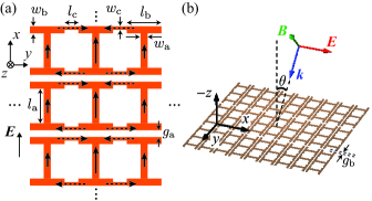
Figure 1(a) shows a schematic of the metamaterial used in this study. We focus on two resonant modes in this metamaterial: electric dipole resonance (the solid arrows indicate its current flow) and magnetic quadrupole-like resonance (represented by the dashed arrows); these modes are, respectively, referred to as modes 1 and 2. Mode 2 has a higher value than mode 1 because the magnetic quadrupole-like oscillator emits less electromagnetic waves than the electric dipole oscillator.
The -polarized incident electric field can directly excite only mode 1. Mode 2 cannot be directly excited because the current flow of mode 2 is perpendicular to the incident electric field. The two resonant modes are magnetically coupled when the incident electromagnetic field has a field gradient. When the -polarized electric field has a gradient in the direction, the induced current of mode 1 depends on . The difference between adjacent currents generates a magnetic flux in the loop of mode 2 and induces antiparallel currents via the electromotive force. Mode 1, mode 2, and the field gradient in the direction of the component of the incident electric field correspond to the bright mode, dark mode, and coupling strength between these two modes, respectively. Therefore, this system is similar to the classical model of EITGarrido Alzar et al. (2002) and the metamaterial behaves as an EIT-like medium for the -polarized electromagnetic wave.
To achieve variable control of the group delay in the EIT-like metamaterial, the coupling strength between the two resonant modes needs to be controlled. The coupling strength depends on the gradient of the component of the incident electric field in the direction. Thus, the group delay can be varied by changing, for example, the beamwidths of normally incident Gaussian beams, the widths of waveguides,Tamayama et al. (2010) or the incident angle of the plane wave defined in Fig. 1(b). In the present study, we investigate the dependence of the transmission properties of the metamaterial. (One might be concerned that the direct interaction between the incident magnetic field and the dark mode occurs when is large, which causes a reduction in the transmittance at the transparency frequency. However, this effect is negligible for the magnetic quadrupole-like dark mode.)
We fabricated the metamaterial shown in Fig. 1 using a printed circuit board that consisted of a --thick copper film on a --thick polyphenylene ether substrate with a relative permittivity of and a loss tangent of at . The geometrical parameters defined in Fig. 1 are , , , , , , , and .
We measured transmission spectra of the fabricated metamaterial for different incident angles to confirm whether an EIT-like transparency phenomenon is observed. A layer of the metamaterial was placed in free space and two horn antennas connected to a network analyzer were used as a microwave transmitter and receiver.
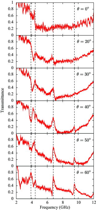
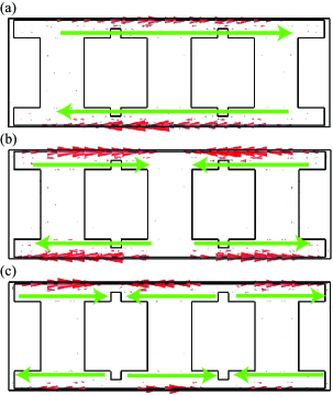
Figure 2 shows the transmission spectra of the metamaterial obtained at six different incident angles. Only a broad absorption line centered on (the resonant frequency of the bright mode) is observed for normal incidence, whereas three narrow transmission windows appear at about 4.2, 6.79, and in the absorption line for oblique incidence. This implies that an EIT-like transparency phenomenon occurs at these three frequencies. The transmission peak at about shifts to lower frequencies with increasing the incident angle, whereas the peaks at 6.79 and exhibit little frequency shift. The transmittance at is higher than that at . Therefore, we consider the transparency window at to be suitable for controlling the group delay.
In order to clarify the resonant modes at the three transmission peak frequencies, we analyzed the metamaterial using a finite element solver, COMSOL Multiphysics. The geometrical parameters used in the numerical analysis were the same as that in the experiment except for the thickness of the copper layer. We set the thickness of the copper layer to for reducing memory consumption in the simulation. This change causes no substantial influence on the simulation results.
Three transmission windows in a broad absorption line for oblique incidence were also observed in the simulation. The current distributions at the frequencies corresponding to the three transmission peaks are shown in Fig. 3. Note that no significant currents are induced in the bright mode at these frequencies. The lowest, middle, and highest frequency resonant modes are found to be a magnetic dipole resonance, an antisymmetric magnetic dipole resonance (magnetic quadrupole-like resonance), and an incompletely antisymmetric magnetic dipole resonance, respectively. It is the middle frequency mode that we described in Fig. 1(a) as the dark mode. The middle frequency mode, or the magnetic quadrupole-like oscillator, has the highest value in the three resonant modes because the current distribution is most antisymmetric. This characteristic causes the high transmittance and small frequency shift of the peak. We find also from the current distribution that the transparency window corresponding to the middle frequency mode is most suitable.
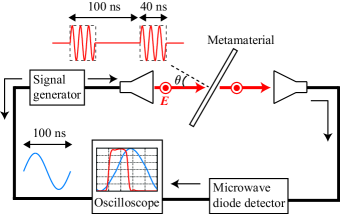
We performed pulse transmission measurements to evaluate the group delay in the metamaterial. Figure 4 shows a schematic of the experimental setup. The arrangement of the metamaterial and the horn antennas was the same as that used to measure the transmission spectrum. A signal generator was used to generate a microwave pulse with a carrier frequency of , a pulse width of , and a period of . This pulse was emitted from the horn antenna and was incident on the single layer of the metamaterial. The transmitted wave was received by the other horn antenna and detected by a microwave diode detector. The output signal of the diode detector (i.e., the envelope of the transmitted pulse) was observed using an oscilloscope. A - sinusoidal wave generated by the signal generator was used as the trigger signal for the oscilloscope. The transmittance and group delay of the metamaterial were determined by comparing the transmitted pulses obtained with and without the metamaterial.
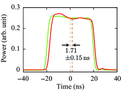
Figure 5 shows the envelope of the transmitted pulse for and that obtained without the metamaterial. The former pulse is delayed by relative to the latter pulse. We regard the delay of the pulse center as being the group delay because it can be shown analytically for Gaussian pulsesYariv (1997) and numerically for other pulses that these delays coincide if third- and higher-order dispersion are negligible. In fact, third- and higher-order dispersion are considered to be small since the transmitted pulse does not exhibit any significant distortion. Note that the width of the transmitted pulse varies due to second-order dispersion (i.e., group delay dispersion).
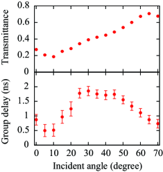
Figure 6 shows the measured transmittance and group delay as a function of the incident angle. The transmittance decreases with decreasing the incident angle, or the coupling strength between the bright and dark modes, due to the finite loss in the dark mode. As the incident angle decreases, the group delay initially increases and reaches a maximum at about , where the transmission bandwidth becomes minimum and the steepest dispersion is obtained. The incident angle for which the group delay takes a maximum value is determined by the losses in the bright and dark modes.Zhang et al. (2008); Tamayama et al. (2010) When the incident angle becomes smaller than , the transparency window gradually disappears and the group delay decreases. The group delay is found to be tunable in the range 0.50–. This observation is consistent with the characteristics of EIT, in which the transmittance decreases with decreasing the intensity of the coupling wave and the group delay takes a maximum value at a certain intensity of the coupling wave.Fleischhauer et al. (2005)
In conclusion, we have achieved variable control of the group delay in a metamaterial with field-gradient-induced transparency. The metamaterial consists of bright and dark modes that are coupled with each other. The group delay in the metamaterial depends on the coupling strength between these two modes. The coupling strength is determined by the field gradient of the incident electromagnetic wave, which allows the group delay to be varied by changing the incident angle. We examined the incident angle dependence of the transmission spectrum of the metamaterial. A broad absorption spectrum was obtained for normal incidence, whereas EIT-like narrow transmission windows were observed for oblique incidence. Pulse measurements revealed that the group delay varies with the incident angle. The maximum group delay can be increased if the value of the dark mode is increased. The small deformation of the transmitted pulse observed in the present experiment can be further suppressed by matching the resonant frequency of the bright mode with that of the dark mode because the shape of the transmission window becomes more symmetric.
This research was supported in part by Grants-in-Aid for Scientific Research (Grants No. 22109004 and No. 22560041), by the Global COE Program “Photonics and Electronics Science and Engineering” at Kyoto University, and by a research grant from the Murata Science Foundation. One of the authors (Y.T.) acknowledges support from the Japan Society for the Promotion of Science.
References
- Harris (1997) S. E. Harris, Phys. Today 50, 36 (1997).
- Hau et al. (1999) L. V. Hau, S. E. Harris, Z. Dutton, and C. H. Behroozi, Nature 397, 594 (1999).
- Fleischhauer et al. (2005) M. Fleischhauer, A. Imamoglu, and J. P. Marangos, Rev. Mod. Phys. 77, 633 (2005).
- Saleh and Teich (2007) B. E. A. Saleh and M. C. Teich, Fundamentals of Photonics, 2nd ed. (John Wiley & Sons, Hoboken, NJ, 2007).
- Smith et al. (2004) D. D. Smith, H. Chang, K. A. Fuller, A. T. Rosenberger, and R. W. Boyd, Phys. Rev. A 69, 063804 (2004).
- Yanik et al. (2004) M. F. Yanik, W. Suh, Z. Wang, and S. Fan, Phys. Rev. Lett. 93, 233903 (2004).
- Totsuka et al. (2007) K. Totsuka, N. Kobayashi, and M. Tomita, Phys. Rev. Lett. 98, 213904 (2007).
- Yang et al. (2009) X. Yang, M. Yu, D.-L. Kwong, and C. W. Wong, Phys. Rev. Lett. 102, 173902 (2009).
- Liu and Yariv (2009) H.-C. Liu and A. Yariv, Opt. Express 17, 11710 (2009).
- Fedotov et al. (2007) V. A. Fedotov, M. Rose, S. L. Prosvirnin, N. Papasimakis, and N. I. Zheludev, Phys. Rev. Lett. 99, 147401 (2007).
- Zhang et al. (2008) S. Zhang, D. A. Genov, Y. Wang, M. Liu, and X. Zhang, Phys. Rev. Lett. 101, 047401 (2008).
- Liu et al. (2008) N. Liu, S. Kaiser, and H. Giessen, Adv. Mater. 20, 4521 (2008).
- Papasimakis et al. (2008) N. Papasimakis, V. A. Fedotov, N. I. Zheludev, and S. L. Prosvirnin, Phys. Rev. Lett. 101, 253903 (2008).
- Papasimakis et al. (2009) N. Papasimakis, Y. H. Fu, V. A. Fedotov, S. L. Prosvirnin, D. P. Tsai, and N. I. Zheludev, Appl. Phys. Lett. 94, 211902 (2009).
- Tassin et al. (2009a) P. Tassin, L. Zhang, T. Koschny, E. N. Economou, and C. M. Soukoulis, Phys. Rev. Lett. 102, 053901 (2009a).
- Tassin et al. (2009b) P. Tassin, L. Zhang, T. Koschny, E. N. Economou, and C. M. Soukoulis, Opt. Express 17, 5595 (2009b).
- Liu et al. (2009) N. Liu, L. Langguth, T. Weiss, J. Kästel, M. Fleischhauer, T. Pfau, and H. Giessen, Nature Mater. 8, 758 (2009).
- Yannopapas et al. (2009) V. Yannopapas, E. Paspalakis, and N. V. Vitanov, Phys. Rev. B 80, 035104 (2009).
- Chiam et al. (2009) S.-Y. Chiam, R. Singh, C. Rockstuhl, F. Lederer, W. Zhang, and A. A. Bettiol, Phys. Rev. B 80, 153103 (2009).
- Verellen et al. (2009) N. Verellen, Y. Sonnefraud, H. Sobhani, F. Hao, V. V. Moshchalkov, P. V. Dorpe, P. Nordlander, and S. A. Maier, Nano Lett. 9, 1663 (2009).
- Tamayama et al. (2010) Y. Tamayama, T. Nakanishi, Y. Wakasa, T. Kanazawa, K. Sugiyama, and M. Kitano, Phys. Rev. B 82, 165130 (2010).
- Lu et al. (2010) Y. Lu, J. Y. Rhee, W. H. Jang, and Y. P. Lee, Opt. Express 18, 20912 (2010).
- Kurter et al. (2011) C. Kurter, P. Tassin, L. Zhang, T. Koschny, A. P. Zhuravel, A. V. Ustinov, S. M. Anlage, and C. M. Soukoulis, Phys. Rev. Lett. 107, 043901 (2011).
- Garrido Alzar et al. (2002) C. L. Garrido Alzar, M. A. G. Martinez, and P. Nussenzveig, Am. J. Phys. 70, 37 (2002).
- Yariv (1997) A. Yariv, Optical Electronics in Modern Communications, 5th ed. (Oxford University Press, New York, NY, 1997).