Speckles generated by skewed, short-coherence light beams
Abstract
When a coherent laser beam impinges on a random sample (e.g. a colloidal suspension), the scattered light exhibits characteristic speckles. If the temporal coherence of the light source is too short, then the speckles disappear, along with the possibility of performing homodyne or heterodyne scattering detection or photon correlation spectroscopy. Here we investigate the scattering of a so-called “skewed coherence beam”, i.e., a short-coherence beam modified such that the field is coherent within slabs that are skewed with respect to the wave fronts. We show that such a beam generates speckles and can be used for heterodyne scattering detection, despite its short temporal coherence. Moreover, we show that the heterodyne signal is not affected by the multiple scattering. We suggest that the phenomenon presented here can be used as a mean to perform heterodyne scattering measurement with any short-coherence radiation, including X-rays.
pacs:
42.30.Ms, 42.25.Fx, 42.25.Kb1 Introduction
Observing of the light diffused from a scattering sample is a widely used, well-known tool applied to the study of biophysical systems, colloidal suspensions, and complex fluids [1]. Homodyne dynamic light scattering and heterodyne detection are based on interference and, in particular, on the observation of speckle patterns. In this case, a long coherence is needed because the light path difference of the interfering beams must not exceed the coherence length. On the other hand, the disappearance of interference beyond the coherence length may be exploited to select a well-defined slab from a thick sample, for example in optical coherence tomography [2].
A single-mode laser beam has a very long longitudinal coherence and is transversally coherent across its section. In a beam with a short longitudinal coherence, the regions in which the electric field is correlated are slabs perpendicular to the beam direction. Using a dispersing optical element, it is possible to manipulate such a beam so that the coherent slabs are skewed by an angle with respect to the plane perpendicular to the beam direction [3]. This effect has been extensively studied in the context of ultra-short optical pulses [4, 5], and it can be utilized to achieve more efficient nonlinear pulse generation (by increasing the phase-matching condition) [6, 7], or to avoid some linear side effects (such as group velocity mismatch and walk-off) [8].
In this paper, we describe the scattering of a skewed coherence beam by a random medium. In the near-field images of the sample, we observe that a skewed coherence beam gives rise to a speckle pattern that is not visible using short-coherence illumination, although the coherence length is identical. Thanks to the visibility of the speckle pattern, our experimental setup with the skewed coherence beam can be used as a so called Scattering In Near Field (SINF) device [9, 10] that operates in a heterodyne detection configuration. Accordingly, we are able to obtain heterodyne light scattering measurements despite the short coherence of the illumination.
2 Experimental setup
Our short-coherence light source is a laser diode driven under threshold (Sacher Lasertechnik SAL-0660-025). The emission has a maximum at a wavelength of 660 nm, with an 8 nm FWHM bandwidth. The regions of the emitted beam in which the field is coherent consist of thin slabs that are orthogonal to the direction of propagation and whose thickness equals the longitudinal coherence length (i.e. about 17 m).
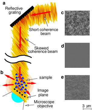
To obtain the desired skewed coherence, the beam is diffracted by a reflective grating [5, 3], with 600 lines per millimeter, blazed at , and the first order diffracted beam is selected (see Fig. 1a). In the resultant beam, the regions in which the field is coherent are slabs that are skewed (inclined) by an angle with respect to a direction perpendicular to the propagation direction [5, 3]. In our case, the skew angle can be adjusted from about to by changing the incidence angle of the beam with respect to the grating.
As shown in Fig. 1b, the skewed beam passes through a 1 mm-thick cell containing the scattering sample (e.g. a colloidal suspension).
The intensity of the light in a plane close to the exit face of the cell is imaged by a CCD camera (Luca Andor) through a high numerical aperture microscope objective (MO; Nikon CFI Plan Apochromat 63X NA 1.4), which collects both the transmitted and scattered beams (heterodyne detection).
3 Experimental results
The images obtained by illuminating the sample with a laser beam (Fig. 1c) clearly show the usual near field speckle patterns [11, 12], with a strong contrast, due to the random interference of the scattered beams. When a non-skewed beam (i.e. ) with a short temporal coherence is used (Fig. 1d), the speckles are almost invisible and appear extremely smeared because no interference can occur. Quite surprisingly, the images obtained with the skewed beams (i.e. ) do show speckles (Fig. 1e), although their texture is different from that which is observed for laser light.
| (a), | (b), |
 |
 |
| (c), | (d), |
 |
 |
(e)
|
|
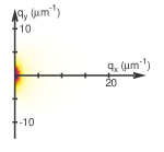
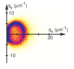
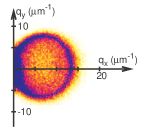
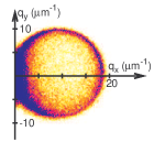
To characterize the speckle fields, we evaluated the power spectra of the images obtained with beams skewed at various angles; the results are reported in Fig. 2. The power spectrum at exhibits a weak signal for the wave vectors close to the center of the Fourier-space image: this corresponds to the faint speckles. As the skew angle is increased, higher frequency modes appear in the images; in the power spectra, they appear as ellipses. The size of the ellipse in the power spectrum increases as the skew angle is increased.
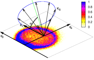
These images can be interpreted as holograms of the scattered field. Each point in the near-field image (with wave vector ) is generated by the interference between the most intense transmitted beam (with wave vector ) and a single scattered beam (with wavevector ). The relationship among , and is shown graphically in Fig. 2e; the wave vector is the projection of the transferred wave vector in the image plane [13]. The SINF technique [9, 14, 13, 15] exploits this relationship to measure the scattering intensity by acquiring near-field images. In this case, the following observations can be made: i) the observed ellipses correspond to scattering along a cone; ii) the impinging beam direction is a generatrix of the cone; iii) the axis of the cone is orthogonal to the coherent slabs. In reality, the sample scatters at all angles, but only the scattering along the cone beats coherently with the local oscillator to provide a detectable heterodyne signal. Thus it will be called the “scattering detection cone” (SDC).
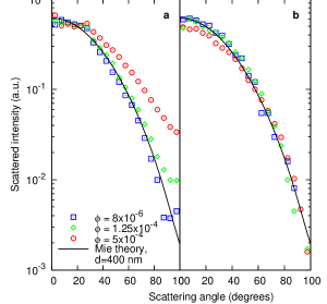
Following the idea of SINF, we can recover the scattering intensities from the power spectra. The results for both a laser beam and a skewed coherence beam are shown in Fig. 3. In both cases, at a low volume fraction, the measured scattering intensity closely follows the Mie theory [16]. This shows that the detected light, scattered along the SDC, has the same direction and intensity as the light scattered by the particles, and the SDC acts only as a mask. By skewing the coherence, we can perform heterodyne detection, despite the short coherence of our light source.
When using laser light, we observe a progressive departure from the Mie theory for large scattering wave vectors [16], that can be easily interpreted to be due to multiple scattering. In contrast, the use of the skewed beam (Fig. 3b) results in an almost perfect overlap between the data and the theoretical results single scattering, independent of the nanoparticle concentration. This experiment shows that the use of skewed coherence beams in a heterodyne scattering detection setup suppresses the detection of multiple scattered light.
4 Discussion
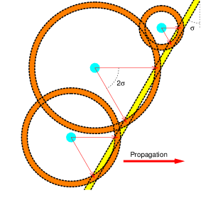
Figure 4 presents a schematic explanation of the obtained results. A coherent slab impinges on a set of particles, which emit secondary waves. Interference only occurs where there is overlap between the coherent slab and the parts of the secondary waves that are coherent with it. In the section shown, overlap only occurs at two points, which define the two directions (indicated by arrows) along which the scattered waves interfere with the impinging beam. One is always along the forward direction, and the other is at a scattering angle of . This direction is identical for every particle. In three dimensions, the intersection of the coherent slab with the secondary spherical wave occurs along a circle, which defines a scattering cone with properties identical to those of the SDC.
From this simplified picture of the interference generated by a skewed beam, one can also infer why multiple scattering is not detected in this configuration. In fact, light that has been scattered more than once will arrive at the screen plane with a time shift greater than the beam’s temporal coherence, thereby preventing interference.
When we take into account the thickness of the coherent slabs, we notice that the secondary waves indeed interfere with the impinging beam for an interval of directions around , whose extent increases as the distance from the coherent slab of the impinging beam to the emitting particle decreases. In particular, if we analyze a plane inside the sample, the particles whose distance from the detection plane is less than the coherence length can give an heterodyne signal at every angle. In other words, only a thin volume around the detection plane contributes to the scattering signal at a generic angle, but the whole volume of the sample contributes to the heterodyne signal along the SDC. This explains why the heterodyne signal along the SDC is much higher than along other directions.
In general, the manipulation of the coherent slab allows to select the volume of the sample which is detected: in our experiments, we are interested in extending this volume up to the whole sample; on the other hand, the so-called “optical coherence tomography” [2] exploits the short coherence for selecting a well defined slice of the sample (this is the meaning of “tomography”, namely “drawing the image of a slice”). This view makes evident the deep analogy between the rejection of the multiple scattering in our experiment and the rejection of the slices other than the selected one in optical coherence tomography.
5 Applications
Currently, measuring the skew angle of a sample beam is performed using non-linear optics and only in the case of ultra-short pulses with high energy [17]. However, the phenomenon described here enables the development of a much simpler technique based on observing the SDC in the power spectra; the axis of the SDC directly provides the normal to the coherence slabs. Such a technique would also be effective for faint beams, and both for continuous waves and ultra-short pulses.
Furthermore, multiple scattering is a serious issue affecting scattering measurements, and several techniques have been developed to suppress the contributions of multiple scattering (e.g. ref. [18, 19] and references therein). This experiment shows that the use of skewed coherence beams in a heterodyne scattering detection setup suppresses multiple scattering and represents the most natural and effective way to reach this target.
In the case of X-rays [20, 21, 22, 23, 24] the coherence conditions necessary for obtaining interference can be achieved by synchrotron radiation or FEL. However, this only occurs after filtering through a monochromator, which strongly reduces the photon flux. Our findings suggest that skewing the coherence of a short-coherence X-ray beam can enable heterodyne detection.
The actual optical scheme will depend on the application. For example, the main beam of a small-angle X-ray scattering (SAXS) apparatus can be used. In this case, the angular dispersion of the beam is much less than 1/1000 of radiant, which ensures a transversal coherence length of the order of the micron, while the transversal coherence is of the order of a few nanometers. In order to obtain the skewed-coherence beam, a transversally coherent region of the main beam is selected by means of a pin-hole, the resulting beam is sent through a transmission grating with a line spacing of the order of 100 nm, and the first-order diffracted beam is selected by a second pin-hole. The resulting beam has a skew angle of the order of the milliradiants, and the corresponding SDC has an aperture of the same order, which is in the range usually detected with SAXS. The SINF detection scheme can still be applied with a variant with respect to the above-described method. Instead of taking an image of a plane, we will place an intensity mask (a transmission grating) on the same plane, with the wave vector we want to measure. The transmitted intensity will represent the amplitude of the corresponding Fourier mode of the image, and will represent the heterodyne signal.
6 Conclusions
We have shown that the use of a skewed-coherence beam allows to detect a heterodyne signal also with short-coherence light. We show that it is possible to skew the coherence of a short-coherence beam by means of an optical system including a diffraction grating. Anyhow, the skewing optical system do not increase the coherence length, nor it acts as a narrow bandwidth filter. The detection is possible only for light scattered along the SDC, while the other scattering directions give a negligible heterodyne signal. The axis of the SDC is perpendicular to the coherent slabs, and thus the detection of the SDC represents a very effective method for measuring the coherence skewness of either a continuous wave or a pulsed beam. When applied to quite turbid samples, the technique has the remarkable advantage of suppressing the multiple scattering contribution of the scattering signal. We suggest that the phenomenon presented here can be used as a mean to perform heterodyne scattering measurement with any short-coherence radiation, and the application of the technique to X-rays has been discussed.
Bibliography
References
- [1] F. Scheffold and R. Cerbino. New trends in light scattering. Curr. Opin. Colloid Interface Sci., 12:50–57, 2007.
- [2] D. Huang et al. Optical coherence tomography. Science, 254(5035):1178–1181, 1991.
- [3] A. Picozzi and M. Haelterman. Hidden coherence along space-time trajectories in parametric wave mixing. Phys. Rev. Lett., 88(8):083901–1–4, 2002.
- [4] O. E. Martinez. Pulse distortions in tilted pulse schemes for ultrashort pulses. Optics Communications, 59(3):229–232, 1986.
- [5] M. A. Porras, G. Valiulis, and P. Di Trapani. Unified description of Bessel X waves with cone dispersion and tilted pulses. Phys. Rev. E, 68:016613–1–11, 2003.
- [6] O. E. Martinez. Achromatic phase matching for second harmonic generation of femtosecond pulses. IEEE J. Quantum Electron., 25:2464–2468, 1989.
- [7] G. Szabo and Z. Bor. Broadband frequency doubler for femtosecond pulses. Appl. Phys. B, 50:51–54, 1990.
- [8] P. Di Trapani et al. Observation of temporal solitons in second-harmonic generation with tilted pulses. Phys. Rev. Lett., 81(3):570–573, 1998.
- [9] D. Brogioli et al. Nano-particle characterization by using exposure time dependent spectrum and scattering in the near field methods: how to get fast dynamics with low-speed ccd camera. Opt. Express, 16:20272–20282, 2008.
- [10] F. Croccolo and D. Brogioli. Quantitative fourier analysis of schlieren masks: the transition from shadowgraph to schlieren. Appl. Opt., 50, 2011.
- [11] J. W. Goodman. Speckle phenomena in optics: theory and applications. Roberts and Company Publishers, Greenwood Village, Colorado, 2009.
- [12] M. Giglio et al. Near-field intensity correlations of scattered light. Appl. Opt., 40:4036–4040, 2001.
- [13] D. Brogioli et al. Nanoparticle characterization by using tilted laser microscopy: back scattering measurement in near field. Opt. Express, 17(18):15431–15448, 2009.
- [14] D. Brogioli et al. Characterization of anisotropic nano-particles by using depolarized dynamic light scattering in the near field. Opt. Express, 17(3):1222–1233, 2009.
- [15] R. Cerbino and V. Trappe. Differential dynamic microscopy: probing wave vector dependent dynamics with a microscope. Phys. Rev. Lett., 100:188102–1–4, 2008.
- [16] H. C. van de Hulst. Light Scattering by Small Particles. Dover, New York, 1957.
- [17] Single-shot autocorrelator ”TIPA” produced by Light Conversion (Vilnius, Lithuania), http://www.lightcon.com/products/product.php?ID=115.
- [18] C. Moitzi et al. A new instrument for time-resolved static and dynamic light-scattering experiments in turbid media. J. Coll. Interf. Sci., 336:565–574, 2009.
- [19] P. N. Pusey. Suppression of multiple scattering by photon cross-correlation techniques. Curr. Opin. Colloid Interface Sci., 4:177–185, 1999.
- [20] M. Sutton. A review of X-ray intensity fluctuation spectroscopy. Comptes rendus physique, 9:657–667, 2008.
- [21] M. Sutton et al. Observation of speckle by diffraction with coherent x-rays. Nature, 352:608–610, 1991.
- [22] S. G. J. Mochrie et al. Dynamics of block copolymer micelles revealed by x-ray intensity fluctuation spectroscopy. Phys. Rev. Lett., 78:1275, 1997.
- [23] R. Cerbino et al. X-ray-scattering information obtained from near-field speckle. Nat. Phys., 4:238–243, 2008.
- [24] K. A. Nugent. Coherent methods in the X-ray sciences. Advances in Physics, 59, 2010.
Acknowledgements
This work was partially financially supported by the EU (project NAD CP-IP 212043-2). F.C. acknowledges his present support from the European Union (Marie Curie funding, contract IEF-251131; DyNeFl project).