Nonadiabatic generation of spin currents in a quantum ring with Rashba and Dresselhaus spin-orbit interactions
Abstract
When subjected to a linearly polarized terahertz pulse, a mesoscopic ring endowed with spin-orbit interaction (SOI) of the Rashba-Dresselhaus type exhibits non-uniform azimuthal charge and spin distributions. Both types of SOI couplings are considered linear in the electron momentum. Our results are obtained within a formalism based on the equation of motion satisfied by the density operator which is solved numerically for different values of the angle , the angle determining the polarization direction of the laser pulse. Solutions thus obtained are later employed in determining the time-dependent charge and spin currents, whose values are calculated in the stationary limit. Both these currents exhibit an oscillatory behavior complicated in the case of the spin current by a beating pattern. We explain this occurrence on account of the two spin-orbit interactions which force the electron spin to oscillate between the two spin quantization axes corresponding to Rashba and Dresselhaus interactions. The oscillation frequencies are explained using the single particle spectrum.
pacs:
73.23.Ra, 71.70.Ej, 72.25.Dc, 73.21.Hb1 Introduction
The controlled induction of spin and charge currents in mesoscopic rings represents a longstanding interest of experimentalists and theorists alike. By taking advantage of the right-left asymmetry of the electron states, various methods have been proposed over the years to this end [1, 2, 3]. In particular, by applying an ultrashort, terahertz frequency laser pulse with spatial asymmetry, the charge and spin excitations are realized in a non-adiabatic regime, since their excitation occurs on a time scale that is much shorter than the electron relaxation lifetime [3, 4, 5]. More recently, these ideas have been reconsidered in the case of rings made out of zinc-blend semiconductor structures that exhibit spin-orbit interaction (SOI). The linear coupling between the electron momentum and spin appears as a result of broken inversion symmetry that results from spatial confinement (Rashba - R) [6] or from bulk properties (Dresselhaus - D) [7]. Under these general circumstances, it was shown that the spin and charge flow simultaneously [8, 9, 10] and special configurations, such as hybrid structures [11] or a number constraint (odd number of particles) [12] are needed to isolate the spin contribution. Recently, we demonstrated that by applying a two-component terahertz frequency pulse, for certain values of the phase difference angle between the two components, a pure spin current is non-adiabatically induced in the ring. Physically, this situation is a consequence of the interplay between SOI which rotates the electron spin around the ring and the asymmetry of the external perturbation embodied by .
The present paper discusses a follow-up to this analysis by studying the effect of a terahertz laser pulse on a ring endowed with both Rashba and Dresselhaus spin-orbit couplings. The coexistence of these couplings introduces precession effects of the electron spin along different directions, a phenomenon bound to affect the spin and charge distributions around the ring. Our formalism is based on obtaining the stationary solutions of the equation of motion satisfied by the particle-density operator which are later employed in estimating the spin and charge currents as as statistical averages. The three independent parameters of the problem are the phase of the laser excitation, , and the coupling strengths of the Rashba and Dresselhaus interactions. Our main result is that, for comparable R and D intensities, the spin current, calculated along the direction, showcases an oscillatory pattern that results from the nutation of the electron spin between the two natural directions associated with the two spin-orbit interactions.
2 The Equilibrium Hamiltonian
We consider a one-dimensional (1D) quantum ring of radius in the presence of both Rashba and Dresselhaus spin-orbit interactions. The ring is discretized in sites with a lattice constant . The polar coordinates are chosen such that the site with index has an azimuthal angle . We denote by and the creation and annihilation operators for an electron with spin on the site .
In the following considerations we adopt the discrete representation of the Hamiltonian that describes the non-interacting electron dynamics around the ring in the presence of the Rashba (R) and Dresselhaus (D) SOI couplings. Its components are:
| (1) |
| (2) |
| (3) |
Three different energy scales are introduced: the hopping energy , Rashba energy and Dresselhaus energy , with and being SOI parameters and the effective mass of the electron in the host semiconductor material. It is customary to introduce the radial and azimuthal spin matrices and
| (4) |
In the presence of only one type of SOI, either Rashba or Dresselhaus, the eigenstates of the Hamiltonian can be obtained analytically [9, 10, 8]. In both cases, the spin quantization axis is tilted relatively to the axis by angles and respectively, given by
| (5) |
where . Consequently, if either or , there exist a corresponding natural direction of the spin, given by or , respectively, along which the projection of the electron spin is conserved and equal to . The directions and are called the principal spin axes, or Rashba and Dresselhaus spin quantization axes, respectively. The difference between the Rashba and the Dresselhaus SOIs is reflected by the orientation of the spin precession relatively to the orbit: in the Rashba case, the precession and the orbital angular speed have the same sign, whereas in the Dresselhaus case they are opposite [13, 10].
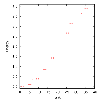
When both interactions are present the diagonalization of the Hamiltonian can be performed only by numerical methods. The energy spectrum for sites and with and is shown in Fig. 1. Each state is double (spin) degenerated. For a ring radius nm our SOI strengths become comparable to those in experimental materials [13]. One obtains meVnm for InAs (i. e. using ), or meVnm for InSb (i. e. using ). Our time unit is , corresponding to ps for InAs and ps for InSb. We will consider (noninteracting) electrons in the ring. The occupied states have energies . The next three energy values are (units of ). The even and odd labels correspond to positive and negative spin chiralities, respectively.
The combination of the two types of SOI breaks the circular symmetry of the electron distribution and creates a charge deformation as shown in Fig. 2. This effect has been discussed in the recent literature both for one-dimensional [10] and two-dimensional [14] quantum rings. In the one-dimensional ring model the charge density has two minima along the direction and two maxima along .
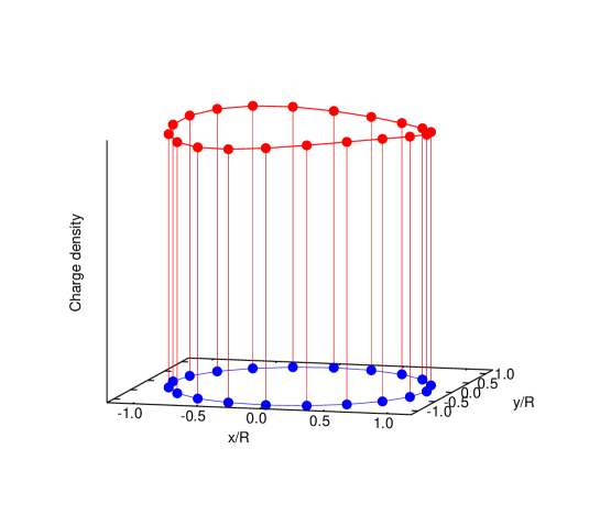
The effect can be explained by an intrinsic periodic potential that develops around the ring [10],
| (6) |
3 Time dependent perturbation
At time the quantum ring is excited by a short terahertz laser pulse linearly polarized along a direction making the angle with the axis. The pulse has a lifetime of and an angular frequency and can be represented by the time dependent Hamiltonian
| (7) |
The time evolution of the system is given by the Liouville equation,
| (8) |
where is the time dependent statistical operator. The time evolution of the electron states, assumed to be initially in the minimum energy configuration, is described by the numerical solutions of the Liouville equation obtained with the Crank-Nicolson finite difference method [3] with small time steps . The expectation value of any observable is then calculated as .
4 Numerical results
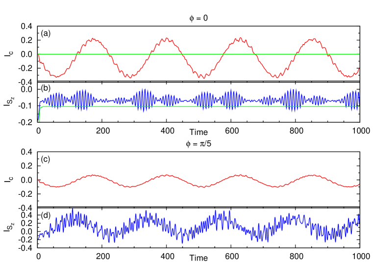
In the following example the pulse parameters are , , and , generating a pulse lifetime of . The time evolution of the charge current for is shown in panel (a) of Fig. 3. After the pulse vanishes, the charge current exhibits a large period oscillatory behavior. At high frequencies, superimposed secondary oscillations are noticeable. These findings can be explained on account of single electron excitations. The large period is correlated with transitions between the second and the third states on the energy scale, and respectively, that generate . Transitions between the states and , occur with period , i. e. one third of the large period, have less weight and cannot be distinguished from the large oscillations. Excitations over larger energy intervals, like , or , etc. are responsible for the finer oscillations, with periods varying from down to or less.
.
.
.
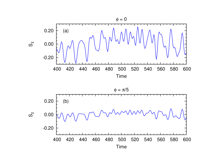
Next, in Fig. 3(b) we illustrate the time evolution of the spin current, defined by , i. e. polarized along the direction, for . This instance indicates more clearly that the time evolution of the system is not periodic even long after the external pulse has vanished. A striking beating pattern is observed, on a background of fast oscillations, faster and much more pronounced than for the charge current. To explain the fast oscillations we refer to Fig. 4, which shows the time dependence of the spin projection on the axis within a time interval of 200 units. A series of double peaks is noticeable created by the two SOI couplings that generate spin torque in opposite directions. The result is a superposition of Rashba and Dresselhaus precessions, with a certain relative phase shift. Consequently, the fast oscillations seen in the charge current are doubled for and for the the spin current. The average time between consecutive maxima in Fig. 4 is about which is about half of the time corresponding to the fast oscillations of the charge current within the same time interval.
We find, therefore, that the spin current is much more sensitive to the single electron transitions between states with distant energies, implicating high frequencies, than the charge current. The beating pattern is a result of that. Since the SOI parameters are different, , the principal spin axes and have different angles with the direction, , and the electron spin executes rapid oscillations between them. In physical terms the orbital motion is accompanied by spin nutation.
At equal SOI parameters, , the principal directions do not coincide, but make the same angle with the axis, . The spin precessions cancel each other and the corresponding spin current vanishes. However the charge current remains qualitatively as in Fig. 3. If only one type of SOI is present, the spin current is not zero, but constant, whereas the charge current vanishes [5], as shown by the green lines in Fig. 3 (a) and (b).
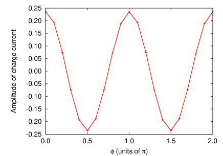
In the lower panels of Figs. 3, (c) and (d), we show the results for the charge and spin currents calculated at . When compared with the previous case, the amplitude of the slow oscillations of the charge current decreases, while that of the spin current increases. Fast oscillations are still pronounced in the spin current. Moreover, the spin current shows similar oscillations as the charge, with a phase shift of , which dominate now the nutation effects. This effect can be explained on account of the anisotropy of the charge distribution shown in Fig. 2. The symmetry axis of the ring corresponds to , and therefore if the pulse is oriented along this direction no charge current is induced. This is seen further in Fig. 5 where we show the amplitude of the charge current vs. the angle , which vanishes for . In this case a spin current of maximum amplitude is induced due to the opposite chiralities of the states. The slow oscillations overlap with the fast fluctuations described earlier. At , the charge current has a maximum amplitude, whereas that of the spin current is minimal and reduced to the fast fluctuations related to spin nutation. The angle is used in Fig. 3(c) and (d) as the closest value to which can be obtained on our discretized ring with 20 sites.
5 Conclusion
The simultaneous effect of Rashba and Dresselhaus spin-orbit interactions upon spin and charge currents are estimated numerically in a ring geometry. A linearly polarized terahertz laser pulse is used for a non-adiabatic generation of the currents. In the presence of the dual spin-orbit coupling, the charge and spin currents exhibit a quasi-periodic behavior whose amplitude depends on the relative angle between the pulse and the charge deformation created by the SOI effects. The spin current reflects a nutation of the electron spin between the Rashba and Dresselhaus spin quantization axes, superimposed as a fast beating pattern on the main oscillation.
References
References
- [1] M. Moskalets and M. Büttiker, Phys. Rev. B 68, 075303 (2003).
- [2] M. Moskalets and M. Büttiker, Phys. Rev. B 68, 161311 (2003).
- [3] V. Gudmundsson, C. S. Tang, and A. Manolescu, Phys. Rev. B 67, 161301(R) (2003).
- [4] S. S. Gylfadottir, M. Niţă, V. Gudmundsson, and A. Manolescu, Physica E 27, 278 (2005).
- [5] M. Niţă, D. C. Marinescu, A. Manolescu, and V. Gudmundsson, Phys. Rev. B 83, 155427 (2011).
- [6] Y. Bychkov and E. I. Rashba, JETP Lett. 39, 78 (1984).
- [7] G. Dresselhaus, Phys. Rev. 100, 580 (1955).
- [8] J. Splettstoesser, M. Governale, and U. Zülicke, Phys. Rev. B 68, 165341 (2003).
- [9] S. Souma and B. K. Nikolić, Phys. Rev. B 70, 195346 (2004).
- [10] J. S. Sheng and K. Chang, Phys. Rev. B 74, 235315 (2006).
- [11] Q.-f. Sun, X. C. Xie, and J. Wang, Phys. Rev. Lett. 98, 196801, (2007).
- [12] G.-Y. Huang and L.Shi-Dong, Europhys. Lett. 86, 67009, (2009).
- [13] T. Ihn,Semiconductor nanostructures. Quantum states and electronic transport, Oxford University Press, 2010.
- [14] M. P. Nowak and B. Szafran, Phys. Rev. B 80, 195319 (2009).