EFFECTS OF ROTATION ON PULSAR
RADIO PROFILES
Dinesh Kumar and R. T. Gangadhara
Indian Institute of Astrophysics, Bangalore - 560034
Abstract: We have developed a model for pulsar polarization by taking into account of viewing geometry, rotation and modulation of the emission region. By solving for the plasma dynamics, we deduced the expressions for curvature radiation electric field in time as well as frequency domains. We show that both the ‘antisymmetric’ and ‘symmetric’ types of circular polarization are possible due to the combined effect of aberration, viewing geometry and modulation. We argue that aberration combined with modulation can introduce ‘kinky’ pattern into the PPA traverses.
1 Introduction
Pulsars are fast rotating, highly magnetized neutron stars which sweep the radiation beam towards the observer once in a rotation period. Pulsar radio emission is believed to be coherent curvature radiation emitted by the relativistic plasma bunches streaming out ‘force-freely’ along the open field lines of the super-strong magnetic field, the geometry of which is assumed to be predominantly dipolar. In an inertial observer’s frame (rotating case), the net velocity of the plasma bunches will be offset from the tangents of their associated field lines due to the effect of co-rotation, and hence the emission beam gets aberrated towards the direction of rotation (Gangadhara, R. T. 2005, ApJ, 628, 923). At any rotation phase , observer receives radiation from all the emission points for which particle’s velocity make an angle with the observer’s sight line, where is the Lorentz factor for plasma bunches. The morphology of radio profiles of pulsars are believed to be strongly influenced by the rotation effects such as aberration and retardation (A/R). A relativistic pulsar emission model is being developed by taking into account of the detailed geometry of emission region and aberration.
2 Radiation electric field
By computing the velocity and acceleration of the relativistic plasma, estimated the electric field of radiation, and obtained the spectral distribution by taking Fourier transform. The Stokes parameters: and are being used to specify the polarization state of the radiation. The modeling of Stokes parameters for pulsar radio emission is very important as they have been found to best in exploring the association between the polarization of the observed radiation, the emission mechanism, and the geometry of the emission region (Gangadhara, R. T. 2010, ApJ, 710, 29). The parameter defines the total intensity, and jointly define the linear polarization and position angle of the radiation field , and defines the circular polarization.
3 Simulation of polarization profiles
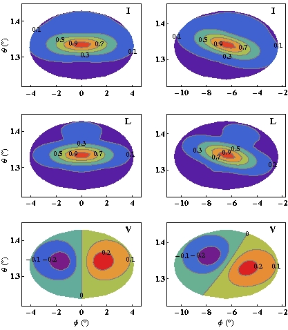
Using the parameters magnetic axis inclination angle sight line impact parameter emission altitude pulsar period s, , and observational frequency MHz, simulated to obtain the parameters: and within the beaming region. Their contour plots are given in magnetic coordinates ()-plane in Figure 1. Emission altitude is and light cylinder radius is where is the speed of light. For comparison presented both the cases: non-rotating (left column panels), and rotating (right column panels). The parameters and in both non-rotating and rotating cases are normalized with the corresponding maximum value of The contour levels are marked on the respective contours. Due to aberration, contour patterns in the rotating case gets rotated in the plane as compared to the corresponding ones in the non rotating case. Hence an asymmetry in the strength of emission occurs within the beaming region bounded by the ranges of and allowed by the geometry. This rotation of pattern is responsible for the wide diversity of circular polarization and position angle swing.
The shapes of pulsar intensity profile indicate that the entire polar cap do not radiate uniformly. In general, pulsar average radio profiles consist of many components: central core emission surrounded by concentric conal emissions. Hence the emission region can be modeled by assuming Gaussian sources distributed within the emission region. Hence a modulation function for a pulse component may defined as
where and are the peak locations and is the amplitude. The parameters and , where and are the full width at half-maxima (FWHM).
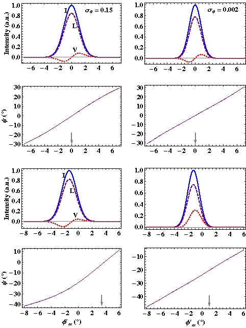
By considering a Gaussian modulation having peak at ( and using the same parameters used for Figure 1, simulated the polarization profiles and presented in Figure 2. To see the combined effect of aberration and modulation, considered two cases of modulation: and 0.002, and kept constant. From top the panels in first and second row are for non-rotating case, and third and last row panels for the rotating case. In all the three cases of , the intensity profiles in the rotating case are found to be shifted to the earlier phase whereas the polarization position angle profiles shifted to the later phase due to aberration. The phase shifts of peak in the cases of and 0.002 are found to be and , respectively. The phase shift of peak is found to decrease with decreasing due to increase in the steepness of the modulation. In the non-rotating case, the circular is always antisymmetric with sign reversal from negative to positive irrespective of the modulation parameters, and in any case negative and positive circulars are of equal magnitude. But in the rotating case, due to combined effect of aberration and modulation, is antisymmetric type in the case of but asymmetric in the positive and negative portions. In the extreme case of , becomes symmetric type, i.e., only strong positive circular survived. The simulations for the first time reproduced this important result on the generation of symmetric type circular polarization.
In all the the cases, the linear polarization almost follows the total intensity except for its lower value due to incoherent addition of Stokes parameters within the beaming region. The polarization position angle swing is counter clockwise, and the position angle inflection points (indicated by arrows) are found to be shifted to later phases by and in the rotating case. The phase shifts of the position angle inflection point is found to decrease with decreasing due to combined effect of aberration and modulation.
4 Conclusion
Developed a relativistic model of pulsar radio emission and polarization. This is for the first time we are able to explain the complete polarization state of the coherent curvature radiation by taking into account of the effect of rotation. Our model predicts both the symmetric as well as antisymmetric type of circular polarization is possible within the frame work of coherent curvature radiation.
Acknowledgment: We thank J. L. Han and Pengfei Wang for stimulating discussions.