A large Bradbury Nielsen ion gate with flexible wire spacing based on photo-etched stainless steel grids and its characterization applying symmetric and asymmetric potentials
Abstract
Bradbury Nielsen gates are well known devices used to switch ion beams and are typically applied in mass or mobility spectrometers for separating beam constituents by their different flight or drift times. A Bradbury Nielsen gate consists of two interleaved sets of electrodes. If two voltages of the same amplitude but opposite polarity are applied the gate is closed, and for identical (zero) potential the gate is open. Whereas former realizations of the device employ actual wires resulting in difficulties with winding, fixing and tensioning them, our approach is to use two grids photo-etched from a metallic foil. This design allows for simplified construction of gates covering large beam sizes up to at least 900 mm2 with variable wire spacing down to 250 µm. By changing the grids the wire spacing can be varied easily. A gate of this design was installed and systematically tested at TRIUMF’s ion trap facility, TITAN, for use with radioactive beams to separate ions with different mass-to-charge ratios by their time-of-flight.
keywords:
Ion switch, Bradbury Nielsen gate, Bradbury Nielsen shutter, photo etching, ion mass spectrometry, TITAN, time of flight separation, time focus, asymmetric switching potential.1 Introduction
In many applications such as ion mass or ion mobility spectrometers, it is necessary to create pulses from continuous ion sources [1]. Similar requirements apply to particle accelerators, where beam pulses need to have specific temporal profiles. Moreover, at radioactive isotope facilities such as CERN-ISOLDE [2] and TRIUMF-ISAC [3] one typically suffers from isobaric contamination that can be suppressed by isolating the desired rare isotope by its time of flight [4, 5]. The use of Bradbury Nielsen (BN) gates [6] is a common way to realize short ion pulses. These devices require lower voltages, can be more compact and exhibit lower capacitance than alternatives such as deflection plates. The original design of a BN gate consists of two sets of parallel, interleaved wires, with the wire plane perpendicular to the ion beam axis [6]. In the case of identical potential on both wires, generally chosen to coincide with the beam line ground potential, the gate is open and most of the ions penetrate undisturbed. Once a voltage of opposite polarity but equal amplitude is applied, the ions are deflected by an angle as defined in Fig. 1. The deflection angle for round wires is given by111Strictly speaking the formula is only correct for deflection voltages applied during the deflection of the ion. The field geometry from a BN gate makes corrections to this deflection angle quite small. [7]:
| (1) |
The deflection angle depends on the wire diameter , the distance between wires and the ratio of voltage applied to the wires () over the ion’s kinetic energy and the ion charge state, . decreases when the ion is in the vicinity of the gate’s electric field while the potential is switched. Depending on the requirements of the system these parameters can be set so that the ions are deflected in such a way that they cannot reach the detector (a state referred to as gate closed in this paper). Deflected ions are deposited somewhere along the beam line. For a detailed discussion on the deflection angle see [7].
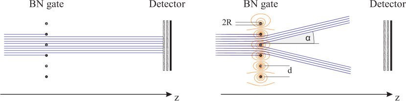
An important property of BN gates is that they only influence the motion of the beam at distances comparable to the wire spacing . This results in a compact design and fast switching, providing a close to ideal definition of a gate in contrast to deflection (kicker) plates. The geometry of BN gates generally also results in smaller capacitance, simplifying the drive circuitry and further aiding the goal of fast switching. More importantly, the spatial dimensions of the gate along the beam axis and thus the disturbance of the ion’s flight path is greatly reduced for BN gates compared to kicker plates.
BN gates of large (cm) size are typically built by stretching wires on frames in various arrangements [8, 9, 10, 11]. This results in substantial complexity and delicate devices that are difficult to assemble and not reliable. This is particularly true when only clean and ultra-high vacuum components can be used. In order to overcome these drawbacks, a new type of BN gate design has been developed based on chemically etched wires. The new design simplifies the construction while at the same time providing far more robust and reliable assemblies. Additionally, the size of the gate is easily scalable, covering large active areas. Currently, an active area of 900 mm2 has been realized where the wire spacing can easily be changed simply by replacing the grids.
2 Gate Design
The critical part in assembling a BN gate is the precise positioning of the two sets of wires isolated from each other. In the design described here, these issues are overcome by using photo-etched grids, as shown in Fig. 2. The basic idea is to handle two wire grids instead of individual wires. In addition, uniform wire tensioning is automatically achieved and the handling of the grids is substantially easier than that of individual wires.
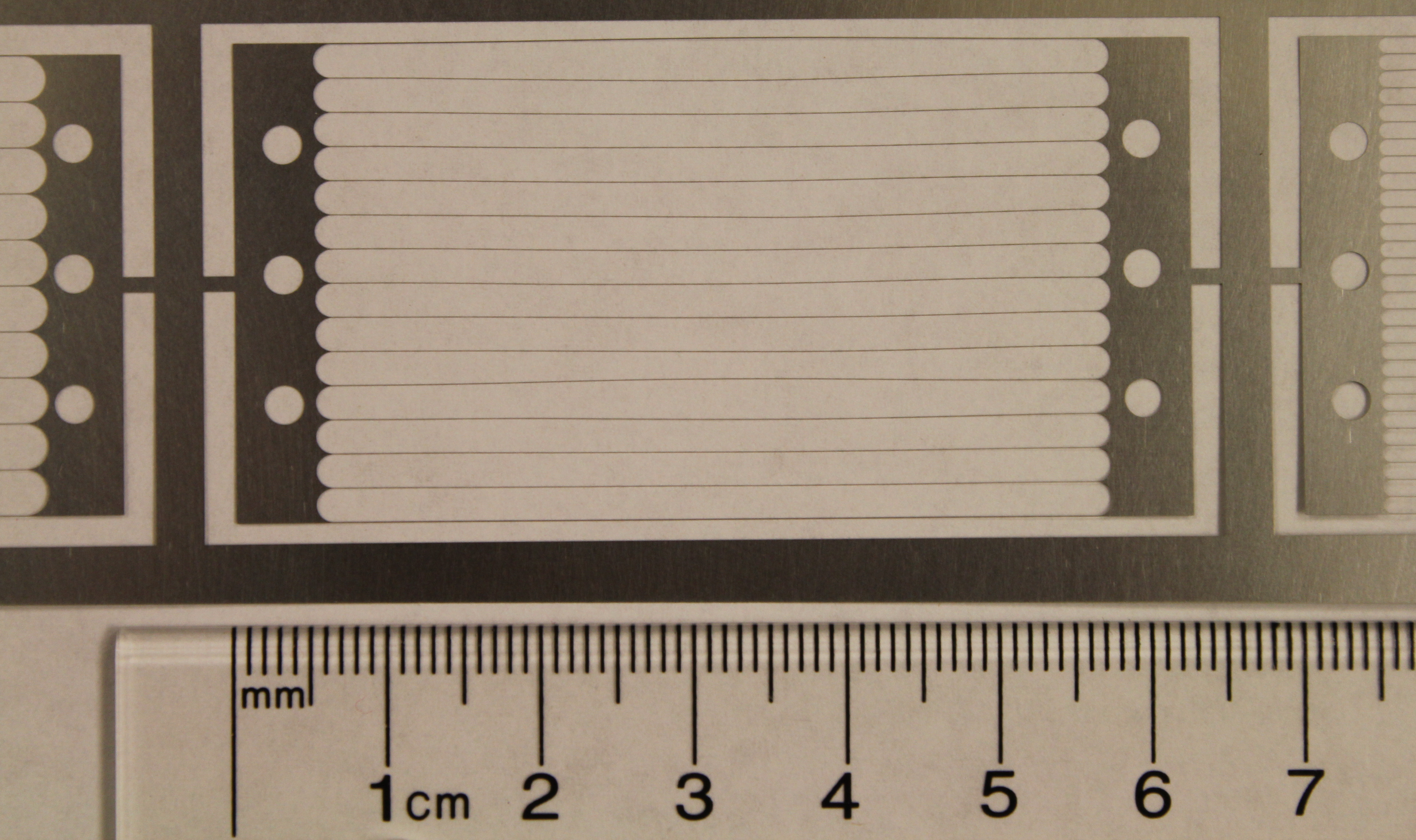
The wire grids described here were photo-chemically etched from a 50.8 µm thick stainless steel sheet by Newcut Inc. [12]. Thus, the resulting wires exhibit the approximate cross section of a diamond with similar dimensions of 50 µm in both thickness and width222The tolerances of metal sheet thickness and wire diameter are 10 % and 13 µm, respectively [13]. The wire diameter cannot be smaller than the thickness of the metal sheet.. While this leads to a field configuration that is different from that of ideal, circular wires, such an effect is only important near the surfaces and we do not expect it to alter the general behavior of the gate, described by Eq.(1). This is because of the large spacing as compared to the wire diameter. Mounting holes were located on each side of the wire grids. The grid-to-grid alignment is provided by the position of the mounting holes. In our design the grid is centered by the mounting screws. If more precise tolerances are required, the positioning of the wire grids could be realized by alignment pins. In order to be able to use identical mounting frames for the two grids, the mounting holes are offset with respect to the symmetry axis of the grid.
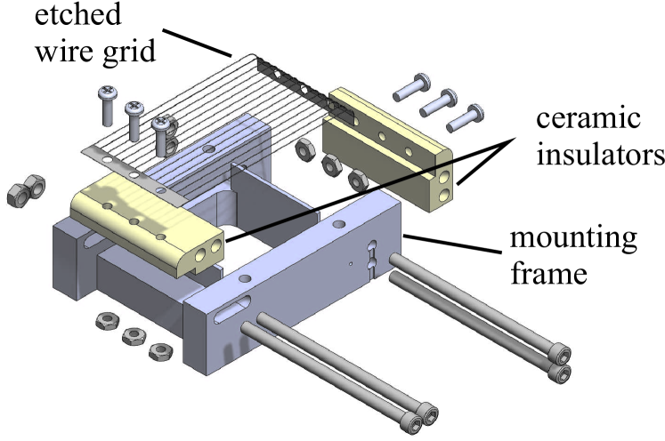
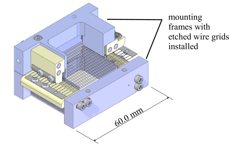
Each grid is mounted onto a pair of macor isolators that is in turn installed onto a stainless steel frame, as shown in Fig. 3. The tension of the grid is set by the screws holding the macor blocks onto the frame and is easily adjusted at the time of assembly. A dedicated tensioning screw pushing the macor blocks apart was found unnecessary for the sizes tested. A rounded edge of the macor blocks allows each grid to have one end bent out of the way, so that when the two frames are mounted against each other, the wires are interleaved and the two grids are not shorted with each other. For simplicity of fabrication, grids, macor blocks and frames are all identical and assembled in a mirrored configuration. A picture of a fully assembled and mounted gate is presented in Fig. 4.
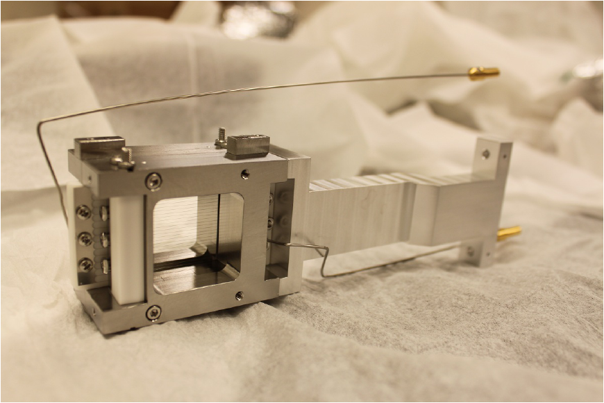
The large extension of the gate body in beam direction protects the grids and acts as the beam dump if the gate is closed. While stainless steel was used to fabricate the grids described here, other metals can be used as well. Because of the intrinsically clean construction materials (macor and stainless steel) a vacuum of mbar was achieved during all measurements.
3 Characterization
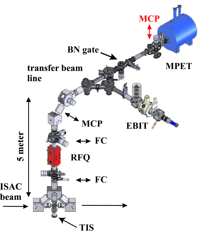
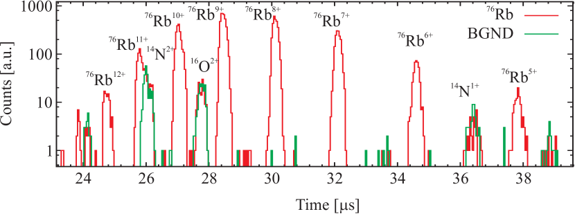
The presented large-area BN gate was installed at TRIUMF’s Ion Trap setup for Atomic and Nuclear science (TITAN) [15]. The TITAN setup consists of several ion traps and is dedicated to high precision measurements of radioactive, short lived nuclei (see e.g. [16, 17, 18, 19]). A schematic of the TITAN facility is presented in Fig. 5 indicating the location of the BN gate. Radioactive isotopes are produced by bombarding an ISOL type [20] target at the Isotope Separation and ACceleration (ISAC) facility [3] with 500 MeV protons. During typical operation, the BN gate is used to separate different isotopes by their time-of-flight when ejected from the first ion trap within the TITAN setup prior to injecting them into a Penning trap [21]. Furthermore, the BN gate is used to isolate ions with certain charge-to-mass ratios after charge breeding in an EBIT [19]. For highly charged ions fast switching times are of particular importance to separate different ion species with very similar . A time-of-flight spectrum of radioactive 76Rb in different charge states is shown in Fig. 6 along with residual background contamination.
For the characterization presented here, a continuous beam of singly charged 39,41K and 85,87Rb ions was extracted from a test ion source through a radio-frequency quadrupole cooler trap, the TITAN RFQ [14], at a beam energy of 3 keV. This beam was then sent towards a micro-channel plate (MCP) ion detector [22]. The BN gate was installed between the RFQ and the MCP detector at a distance of 1.35 m from the MCP detector as illustrated in Fig. 5. For this work, the gate was generally closed and only switched to transparent state (gate open) for a short, well-defined time T. The voltage was switched by two solid state devices developed at TRIUMF. These switches were set up to output either the two voltages and to block the beam, or 0 V to let ions pass through the gate. The rise times at the output of the switches were ns for a voltage set of V. A TTL control signal was provided to the switches by a Tektronix pulse generator (model AFG 3022B) with a rise time of 18 ns. A synchronized TTL signal was then used to trigger the data acquisition, a multi-channel scaler (MCS Stanford Research SR 430). For the characterization of the gate, the ion’s time of flight distribution was recorded varying either the applied voltages and or the opening time T. Typically, the ion’s time of flight was recorded for 20,000 switching cycles at a switching rate of 500 Hz. A schematic of the applied voltages and is displayed at the bottom of Fig. 7. During all studies, the gate assembly displayed in Fig. 4 was installed in a four way cross CF 8” and connected to the switch by 10 cm long standard RG58 SHV cables.
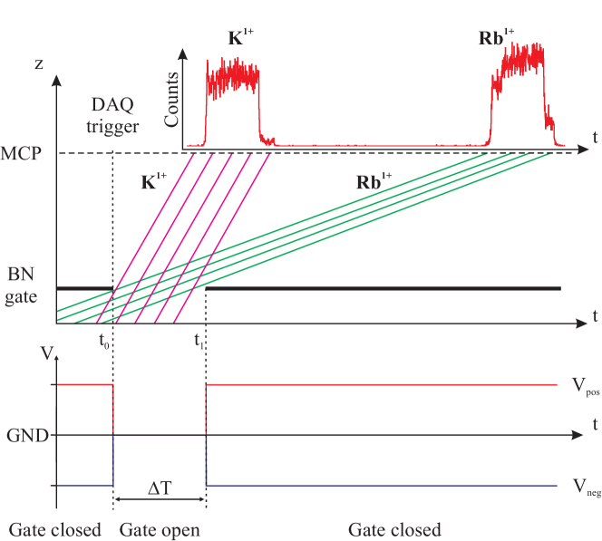
During these studies, grids with µm diameter () and mm spacing () were used, resulting in a transmission of 95%. The incoming beam with an energy of 3 keV had an intensity of 700 k ions/s dominantly consisting of 39,41K and 85,87Rb. Total and individual ion beam intensities were extracted from Fig. 8 and the relative values for the isotopes of each element are found to agree with natural abundances (see Tab. 1). Fig. 7 illustrates schematically the time-of-flight measurement. Here, a steeper slope corresponds to an ion with higher velocity. At a time the gate is opened and ions pass through for a time period T. Lighter nuclides arrive earlier on the detector due to their higher speed, as shown in the figure.
| Isotope | Intensity [k ions/s] | Rel. abundance | Lit. rel. nat. abundance |
|---|---|---|---|
| 39K | 261.3(5) | 89(19)% | 93.2690(44)% |
| 41K | 30.0(2) | 10(2)% | 6.7310(44)% |
| 85Rb | 422.5(7) | 73(8)% | 72.165(20)% |
| 87Rb | 153.8(4) | 27(3)% | 27.835(20)% |
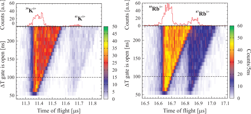
To investigate the minimal time the gate can be opened, a symmetric voltage of V was applied to the gate and switched to ground potential for varying times T from 40 ns to 240 ns in steps of 10 ns. The result of this measurement is presented in Fig. 8 where the ion intensity at the MCP detector is displayed as a function of T and the ion’s time of flight. For ns no ions reached the MCP detector, while for ns the incoming 85,87Rb isotopes were separated in time of flight. The time of flight spectrum for ns is presented at the top of Fig. 8. This value for the time has been used in the following studies, unless stated otherwise.
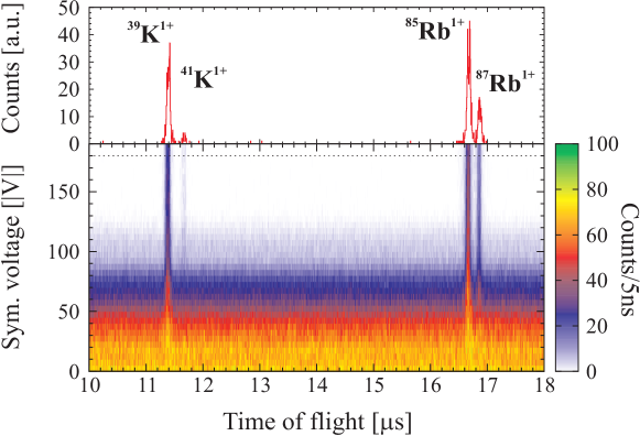
In order to determine the voltage required to deflect the ions sufficiently so that they are unable to reach the MCP detector, the voltage at the wires was increased symmetrically in steps of V. The resulting scan is shown in Fig. 9. For voltages higher than V the gate is fully closed, with a negligible background (on/off ratio of ).
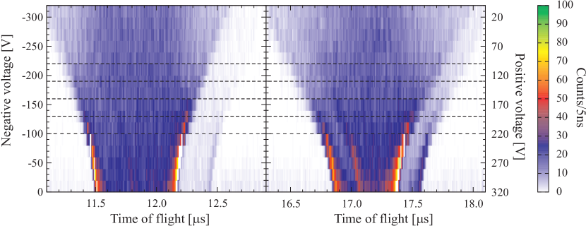
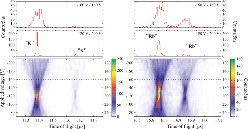
Additional studies were performed to investigate the concept of switching only one set of wires with twice the amplitude. This configuration could save cost of a second switch and power supply. An asymmetric voltage was applied to the wires in such a way that the potential difference between neighboring wires stayed constant at V. The scan started with V and V applied to the wires decrementing the voltage in steps of 20 V, and ending at V and V. During this scan the gate was open for ns. The resulting intensity distribution is presented in Fig. 10 where the vertical axis on the right (left) displays the positive (negative) voltage applied. At V the applied voltage is symmetric. If the net voltage potential is negative, the ion’s time of flight is smeared out while the opposite effect is observed for positive . In this case, the time of flight distribution is compressed with two intense peaks at both sides of the distribution. Due to the long opening time T=1µs, the peaks of the different isotopes overlap but can still be clearly identified.
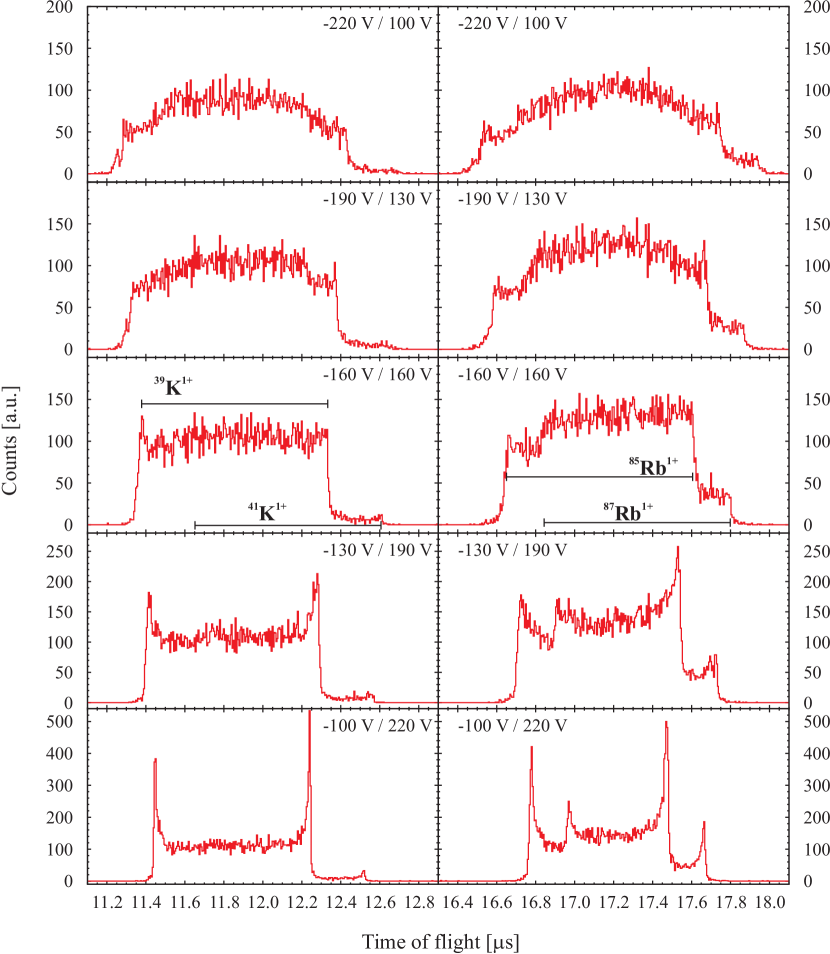
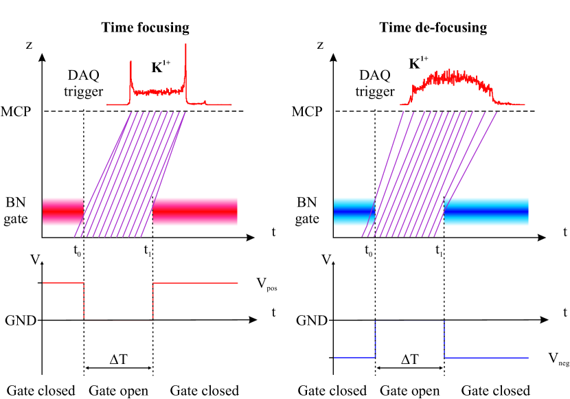
In order to investigate this focusing effect, we recorded time-of-flight spectra for five voltage settings with higher statistics. Starting with the symmetric configuration of V, the voltage was incremented (or decremented) by 30 V and 60 V. The resulting time-of-flight distributions of K and Rb are presented in Fig. 11. This clearly shows the defocussing effect for V and the focusing effect for V. The explanation of this effect is presented in Fig. 12. For the symmetric configuration, the potential is different from zero only in a very small region around the wires on the order of the wire spacing . For asymmetric settings, the field originating from the applied potential acts as an advancing or retarding potential for the ions. This is illustrated by colored bars in Fig. 12 (red for positive and blue for negative net potential). Ions in the vicinity of this potential while the gate is switched encounter an acceleration or deceleration, depending on and their position along the beam axis when the gate is switched, as indicated by the changed slope in Fig. 12. Positive ions are focused in time by while defocuses them, in both cases with the effect of broadening the energy distribution.
This focusing behavior can be used to increase the time of flight separation of the ions as shown in Fig. 13. In this scan, the gate was open for T=100 ns and the voltage was scanned from V to -210 V and V to 110 V in steps of 5 V. The voltage difference was kept constant at 320 V with the symmetric configuration being at V. At a configuration of V the ions are focused in time maximally, therefore leading to an increase in the time-of-flight resolution. However, this has the effect of broadening the ions’ energy distribution. Thus, an asymmetric voltage configuration cannot be used in the assistance of high-precision mass measurements with the TITAN Penning trap spectrometer.
4 Conclusion
In this publication, we present a novel design of the Bradbury Nielsen ion gate along with systematic studies of its performance that were carried out at the TITAN facility. The resulting gate has good mechanical tolerances, it is rugged and simple to assemble. In addition, it is fully UHV compatible and the wire spacing can be rapidly changed to reconfigure the device. The dimensions of the gate are scalable and so far two versions with wire grid areas of 144 mm2 and 900 mm2 have been realized. Larger areas can be realized by adapting the wire design.
Before the BN gate was installed along the TITAN beam line, the common plate of an x-y steering element was used as an ion gate to deflect the incoming beam. With this setup, the gate open time T had to be greater than 300 ns. Using the BN gate, we could improve this time by a factor of 6 allowing substantially better separation of different isotopes by their time of flight in the presented setup. This improvement is due to a lower capacitance of the BN gate (20 pF compared to the 70 pF kicker) and the more favorable geometry. Even shorter gate open times T might be possible with a faster electrical switch. Our measurements in the TITAN setup clearly show the applicability of this new BN gate concept for online applications with short-lived isotopes.
Finally, we investigated the effects of asymmetrical potentials applied to the wire sets and found strong time focusing and defocusing effects. In order not to increase the energy distribution of an ion beam, symmetric potentials have to be used. However, the time focusing effect can be exploited to increase resolution on the detector
5 Acknowledgments
This work was supported, in part, by the US Department of Energy, the US National Science Foundation, the Natural Sciences and Engineering Research Council of Canada and the Canadian National Research Council. One of the authors (TB) acknowledges support by evangelisches Studienwerk e.V. Villigst. S.E. acknowledges support from the Vanier CGS program and M.K. was funded by the DAAD RISE program. We would like to thank M. Solyali for the construction of the gate.
References
- [1] J. Laakia, A. Adamov, M. Jussila, C. Pedersen, A. Sysoev, T. Kotiaho, Separation of different ion structures in atmospheric pressure photoionization-ion mobility spectrometry-mass spectrometry (APPI-IMS-MS), J. Am. Soc. Mass Spectrom. 21 (2010) 1565–1572, 10.1016/j.jasms.2010.04.018.
- [2] E. Kugler, The ISOLDE facility, Hyperfine Interact. 129 (2000) 23–42. doi:10.1023/A:1012603025802.
- [3] M. Dombsky, D. Bishop, P. Bricault, D. Dale, A. Hurst, K. Jayamanna, R. Keitel, M. Olivo, P. Schmor, G. Stanford, Commissioning and initial operation of a radioactive beam ion source at ISAC, Rev. Sci. Instrum. 71 (2000) 978. doi:10.1063/1.1150364.
- [4] D. Rodríguez, K. Blaum, W. Nörtershäuser, M. Ahammed, A. Algora, G. Audi, J. Äystö, D. Beck, M. Bender, J. Billowes, M. Block, C. Böhm, G. Bollen, M. Brodeur, T. Brunner, B. Bushaw, R. Cakirli, P. Campbell, D. Cano-Ott, G. Cortés, J. Crespo López-Urrutia, P. Das, A. Dax, A. De, P. Delheij, T. Dickel, J. Dilling, K. Eberhardt, S. Eliseev, S. Ettenauer, K. Flanagan, R. Ferrer, J.-E. García-Ramos, E. Gartzke, H. Geissel, S. George, C. Geppert, M. Gómez-Hornillos, Y. Gusev, D. Habs, P.-H. Heenen, S. Heinz, F. Herfurth, A. Herlert, M. Hobein, G. Huber, M. Huyse, C. Jesch, A. Jokinen, O. Kester, J. Ketelaer, V. Kolhinen, I. Koudriavtsev, M. Kowalska, J. Krämer, S. Kreim, A. Krieger, T. Kühl, A. Lallena, A. Lapierre, F. Le Blanc, Y. Litvinov, D. Lunney, T. Martínez, G. Marx, M. Matos, E. Minaya-Ramirez, I. Moore, S. Nagy, S. Naimi, D. Neidherr, D. Nesterenko, G. Neyens, Y. Novikov, M. Petrick, W. Plaß, A. Popov, W. Quint, A. Ray, P.-G. Reinhard, J. Repp, C. Roux, B. Rubio, R. Sánchez, B. Schabinger, C. Scheidenberger, D. Schneider, R. Schuch, S. Schwarz, L. Schweikhard, M. Seliverstov, A. Solders, M. Suhonen, J. Szerypo, J. Taín, P. Thirolf, J. Ullrich, P. Van Duppen, A. Vasiliev, G. Vorobjev, C. Weber, K. Wendt, M. Winkler, D. Yordanov, F. Ziegler, MATS and LaSpec: High-precision experiments using ion traps and lasers at FAIR, Eur. Phys. J. 183 (2010) 1–123, 10.1140/epjst/e2010-01231-2. doi:10.
- [5] R. Wolf, M. Eritt, G. Marx, L. Schweikhard, A multi-reflection time-of-flight mass separator for isobaric purification of radioactive ion beams, Hyperfine Interact. 199 (2011) 115–122, 10.1007/s10751-011-0306-8. doi:10.1007/s10751-011-0306-8.
- [6] N. E. Bradbury, R. A. Nielsen, Absolute Values of the Electron Mobility in Hydrogen, Phys. Rev. 49 (5) (1936) 388–393. doi:10.1103/PhysRev.49.388.
- [7] O. K. Yoon, I. A. Zuleta, J. R. Kimmel, M. D. Robbins, R. N. Zare, Duty Cycle and Modulation Efficiency of Two-Channel Hadamard Transform Time-of-Flight Mass Spectrometry, J. Am. Soc. Mass Spectrom. 16 (11) (2005) 1888 – 1901. doi:10.1016/j.jasms.2005.07.025.
- [8] P. R. Vlasak, D. J. Beussman, M. R. Davenport, C. G. Enke, An interleaved comb ion deflection gate for m/z selection in time-of-flight mass spectrometry, Rev. Sci. Instrum. 67 (1) (1996) 68 –72. doi:10.1063/1.1146553.
- [9] J. R. Kimmel, F. Engelke, R. N. Zare, Novel method for the production of finely spaced Bradbury–Nielson gates , Rev. Sci. Instrum. 72 (2001) 4354–4357. doi:10.1063/1.1416109.
- [10] A. W. Szumlas, D. A. Rogers, G. M. Hieftje, Design and construction of a mechanically simple, interdigitated-wire ion gate, Rev. Sci. Instrum. 76 (8) (2005) 086108 –086108–3. doi:10.1063/1.2006308.
- [11] O. Yoon, I. Zuleta, M. Robbins, G. Barbula, R. Zare, Simple Template-Based Method to Produce Bradbury-Nielsen Gates, J. Am. Soc. Mass Spectrom. 18 (2007) 1901–1908.
- [12] Newcut, http://www.newcut.com/.
- [13] Private communication with P. Engel, Newcut.
- [14] T. Brunner, M. Smith, M. Brodeur, S. Ettenauer, A. Lapierre, E. Mané, R. Ringle, M. Simon, P. Delheij, M. Good, M. Pearson, J. Dilling, TITAN’s Digital RFQ Ion Beam Cooler and Buncher, Operation and Performance, arXiv arXiv:1107.2187v1.
- [15] J. Dilling, R. Baartman, P. Bricault, M. Brodeur, L. Blomeley, F. Buchinger, J. Crawford, J. C. López-Urrutia, P. Delheij, M. Froese, G. Gwinner, Z. Ke, J. Lee, R. Moore, V. Ryjkov, G. Sikler, M. Smith, J. Ullrich, J. Vaz, Mass measurements on highly charged radioactive ions, a new approach to high precision with TITAN, Int. J. Mass Spectrom. 251 (2-3) (2006) 198 – 203. doi:10.1016/j.ijms.2006.01.044.
- [16] M. Smith, M. Brodeur, T. Brunner, S. Ettenauer, A. Lapierre, R. Ringle, V. L. Ryjkov, F. Ames, P. Bricault, G. W. F. Drake, P. Delheij, D. Lunney, F. Sarazin, J. Dilling, First Penning-Trap Mass Measurement of the Exotic Halo Nucleus 11Li, Phys. Rev. Lett. 101 (20) (2008) 202501. doi:10.1103/PhysRevLett.101.202501.
- [17] V. L. Ryjkov, M. Brodeur, T. Brunner, M. Smith, R. Ringle, A. Lapierre, F. Ames, P. Bricault, M. Dombsky, P. Delheij, D. Lunney, M. R. Pearson, J. Dilling, Direct Mass Measurement of the Four-Neutron Halo Nuclide 8He, Phys. Rev. Lett. 101 (1) (2008) 012501. doi:10.1103/PhysRevLett.101.012501.
- [18] R. Ringle, M. Brodeur, T. Brunner, S. Ettenauer, M. Smith, A. Lapierre, V. Ryjkov, P. Delheij, G. Drake, J. Lassen, D. Lunney, J. Dilling, High-precision Penning trap mass measurements of 9,10Be and the one-neutron halo nuclide 11Be, Phys. Lett. B 675 (2009) 170. doi:10.1016/j.physletb.2009.04.014.
- [19] A. Lapierre, M. Brodeur, T. Brunner, S. Ettenauer, A. Gallant, V. Simon, M. Good, M. Froese, J. C. López-Urrutia, P. Delheij, S. Epp, R. Ringle, S. Schwarz, J. Ullrich, J. Dilling, The TITAN EBIT charge breeder for mass measurements on highly charged short-lived isotopes–First online operation, Nucl. Instr. and Meth. A 624 (1) (2010) 54 – 64. doi:10.1016/j.nima.2010.09.030.
- [20] J. Äystö, Overview of recent highlights at ISOL facilities, Nucl. Phys. A 805 (1-4) (2008) 162c – 171c, INPC 2007 - Proceedings of the 23rd International Nuclear Physics Conference. doi:10.1016/j.nuclphysa.2008.02.237.
- [21] M. Brodeur, T. Brunner, C. Champagne, S. Ettenauer, M. Smith, A. Lapierre, R. Ringle, V. Ryjkov, G. Audi, P. Delheij, D. Lunney, J. Dilling, New mass measurement of 6Li and ppb-level systematic studies of the Penning trap mass spectrometer TITAN, Phys. Rev. C 80 (4) (2009) 044318. doi:10.1103/PhysRevC.80.044318.
- [22] J. Wiza, Microchannel plate detectors, Nucl. Instrum. Methods 162 (1–3) (1979) 587–601. doi:10.1016/0029-554X(79)90734-1.
- [23] R. B. Firestone, Table of Isotopes CD ROM edition, Wiley-Interscience; 8th edition, 1996.