Capillary filling with giant liquid/solid slip: dynamics of water uptake by carbon nanotubes
Abstract
This article discusses the way the standard description of capillary filling dynamics has to be modified to account for liquid/solid slip in nanometric pores. It focuses in particular on the case of a large slip length compared to the pore size. It is shown that the liquid viscosity does not play a role, and that the flow is only controlled by the friction coefficient of the liquid at the wall. Moreover in the Washburn regime, the filling velocity does not depend on the tube radius. Finally, molecular dynamics simulations suggest that this standard description fails to describe the early stage of capillary filling of carbon nanotubes by water, since viscous dissipation at the tube entrance must be taken into account.
I Introduction
Dynamics of capillary rise is a standard case of coupling between capillarity and hydrodynamics de Gennes et al. (2003); Zhmud et al. (2000). The filling behavior has been investigated since the beginning of the 20th century Lucas (1918); Washburn (1921); Bosanquet (1923); Quere (1997); Stange et al. (2003). In particular, the famous (Lucas-)Washburn law (neglecting the liquid inertia) states that the filling velocity decreases as the inverse square root of time. But this old problem needs to be revisited as regards nanometric pores Schoch et al. (2008); Sparreboom et al. (2009). Even if continuum hydrodynamics remains valid for simple liquids (including water) down to channel sizes of a typical 1 nm Bocquet and Charlaix (2010), surfaces will play an increasing role. In particular, deviations from the classical hypothesis of a no-slip boundary condition (BC) at the liquid/solid interface have been predicted theoretically and observed experimentally Bocquet and Barrat (2007). The simplest way to account for liquid/solid slip is the so-called ’partial slip’ BC, which links the slip velocity with the shear rate at the solid surface : , in which the slip length is the depth inside the solid where the linear extrapolation of the velocity profile vanishes (Fig. 1.a). Let us emphasize here that the slip length, though it has a simple geometric meaning, is not a fundamental property of the liquid/solid interface. Indeed, the partial slip BC physically stems from the continuity of tangential stress at the wall: the viscous shear stress exerted by the liquid on the wall ( being the shear viscosity of the liquid) is equal to the friction force suffered by the liquid from the wall, which can be written as where is the liquid/solid friction coefficient and the contact area. The slip length is accordingly a combination of the bulk liquid viscosity and the interfacial friction coefficient: . For simple liquids on smooth surfaces, slip lengths up to a few tens of nanometers have been experimentally measured Bocquet and Barrat (2007). Liquid-solid slip is therefore expected to significantly affect flows in channels of nanometric size, even when continuum hydrodynamics remains valid.
In recent years, many works have investigated capillary filling at the nanoscale, emphasizing the roles of dynamic contact angle, liquid inertia, and liquid-solid slip Marmur (1988); Martic et al. (2004); Supple and Quirke (2004); Dimitrov et al. (2007); Huber et al. (2007); Cupelli et al. (2008); Schebarchov and Hendy (2008); Gruener et al. (2009); Ahadian et al. (2010); Chen et al. (2010); Stukan et al. (2010); Wu et al. (2010); Phan et al. (2010); Schebarchov and Hendy (2011); Qin et al. (2011). In this context, recent experiments Majumder et al. (2005); Holt et al. (2006); Whitby et al. (2008); Du et al. (2011) and numerical simulations Thomas and McGaughey (2008); Falk et al. (2010) have reported slip lengths of water (and other liquids) in carbon nanotubes (CNT) much larger than the tube radius. This article seeks to investigate the way this quite special condition modifies the dynamics of capillary filling. Firstly, the full equations describing capillary filling with a partial slip boundary condition will be derived and solved. The article will then focus on the case of CNTs where giant liquid/solid slip has been reported. Finally this standard analytical model will be tested against molecular dynamics simulations.
II Analytical model
Before turning to the specific case of water filling a CNT, the equation describing capillary filling with a partial slip boundary condition, taking into account the liquid inertia, will be derived and solved. This model is formally equivalent to the one introduced by Supple and Quirke Supple and Quirke (2004), with the difference that the equation will here be derived in the framework of continuum hydrodynamics, as we have discussed that liquid/solid slip could be significant for channel sizes where continuum hydrodynamics remained valid.

Let’s consider a cylindrical pore of radius , in contact with a reservoir of liquid (density , viscosity ), as illustrated in Fig. 1.a. The liquid surface tension is denoted , and its contact angle on the pore wall (it is assumed that the liquid is wetting the pore, i.e. ). The distance of the meniscus from the pore entrance is denoted . Therefore the velocity of the meniscus , equal to the average liquid velocity inside the pore, is related to through: . The filling dynamics results from the competition between a capillary force at the contact line , driving the motion of the liquid inside the pore, and a viscous friction force at the wall , slowing the liquid motion (gravity can usually be neglected at small scales). One can write the equation of motion for the liquid inside the pore:
| (1) |
where is the mass of liquid inside the pore. We will denote the capillary force per unit length at the contact line, where and are the solid-gas and solid-liquid surface tensions. The total capillary force is then simply given by:
| (2) |
The friction force is given by the Poiseuille law de Gennes et al. (2003); Zhmud et al. (2000), modified to take into account liquid/solid slip Washburn (1921); Schebarchov and Hendy (2008); Chen et al. (2010); Schebarchov and Hendy (2011):
| (3) |
The equation of motion (1) can finally be re-written:
| (4) |
This non-linear equation admits the following solution Supple and Quirke (2004):
| (5) |
with:
| (6) |
and:
| (7) |
One can easily check that in the long time limit, where the liquid inertia can be neglected compared to the viscous friction inside the tube, Eq. (5) simplifies into the well-known Washburn law Washburn (1921); Schebarchov and Hendy (2008); Chen et al. (2010); Schebarchov and Hendy (2011):
| (8) |
On the contrary, in the short time limit viscous friction can be neglected compared to inertia. Eq. (5) simplifies into:
| (9) |
Of course neither the viscosity nor the slip length appear here since the friction term has been neglected. One could finally note that even this inertial regime does not appear instantaneously, essentially because the meniscus shape changes when the liquid enters into the pore. But it can be shown that the meniscus adopts a stationary shape for (from Stange et al. (2003)). Therefore, the pre-inertial regime disappears extremely fast in nanometric pores.
Water inside CNT– Recent experiments Majumder et al. (2005); Holt et al. (2006); Whitby et al. (2008); Du et al. (2011) and numerical simulations Thomas and McGaughey (2008); Falk et al. (2010) have reported surprisingly large slip lengths of water (and other liquids) in carbon nanotubes. The first experiments Majumder et al. (2005) indicated slip lengths up to tens of micrometers, even if more recent experimental Holt et al. (2006) and numerical Falk et al. (2010) works point to a smaller effect, with on the order of a few hundredth of nanometers. When the slip length is much larger than the pore size: , the flow inside the pore will be almost plug-like, namely with a constant velocity profile. In this regime, there is almost no shear inside the liquid, and the viscosity is not expected to play a role. In fact, the viscous term will only depend on the interfacial friction coefficient . This can be seen if one take the limit in Eq. (3):
| (10) |
But this expression can be found directly under the assumption of a perfect plug flow, where the velocity of the liquid is everywhere equal to its average value . The friction force over the liquid/solid contact area is then simply:
| (11) |
Generally the ratio can be replaced by in the equation of motion (1), its solutions Eqs. (8) and (5), and the expression of the transition time (6) and transition length (7). In particular the Washburn law (in the viscous regime) becomes:
| (12) |
In the plug-flow case, viscosity does not play a role, and the flow is only controlled by the friction coefficient. Furthermore, the filling dynamics does not depend on the tube radius anymore. This important difference could be used as a clear experimental signature of a plug flow in the viscous regime.
To compute orders of magnitude, one also needs to quantify the driving force . This is far from trivial: Whereas measurements of water contact angle on highly oriented pyrolytic graphite converge to a value of Alexiadis and Kassinos (2008); Werder et al. (2003), corresponding to for water on a single graphene sheet (hence a non-wetting situation, where water should not invade CNT), there are experimental evidences that water fills at least the very small CNTs Kolesnikov et al. (2004); Cambré et al. (2010); Qin et al. (2011); Kyakuno et al. (2011); Pascal et al. (2011). At these scales however, it is hard to apply macroscopic concepts of capillarity like surface tension and contact angle van Honschoten et al. (2010). But if water indeed fills CNT, will be positive and one can estimate that it will be at most on the order of .
III Molecular Dynamics simulations and discussion
We considered a water reservoir in contact with an initially empty CNT (Fig. 1.b). The CNT length was 10 nm, with radii ranging between 0.514 and 1.87 nm. The reservoir was bordered with two graphene sheets, at a distance large enough to ensure that the liquid water was always in equilibrium with its vapor. Periodic boundary conditions in the two directions perpendicular to the tube axis ensured that the water surface remained planar. Consequently, the pressure in the water reservoir always remained constant, at a value extremely close to zero.
The Amber96 force field Cornell et al. (1995) was used, with TIP3P water and water-carbon interaction modeled by a Lennard-Jones potential between oxygen and carbon atoms, with parameters kcal/mol and Å. The tabulated density, surface tension and viscosity of TIP3P water at 300 K and liquid/vapor coexistence are respectively: g/cm3, N/m (from Vega and de Miguel (2007)), and mPa s (from Gonzalez and Abascal (2010)). The contact angle of water on a single graphene sheet was measured independently to be for this model. The simulations were carried out using LAMMPS Plimpton (1995). Long-range Coulomb forces were computed using the particle-particle particle-mesh (PPPM) method; A timestep of 2 fs was used, unless specified. The positions of the carbon atoms were fixed (simulations with flexible and fixed walls were shown to give similar results for the statics and friction of confined liquids Alexiadis and Kassinos (2008); Thomas and McGaughey (2009); Werder et al. (2003)). Water molecules were kept at a constant temperature of 300 K using a Nosé-Hoover thermostat, applied only to the degrees of freedom perpendicular to the tube axis, with a damping time of 200 fs. Alternatively a Dissipative Particle Dynamics thermostat was used (see details in the following).
Water molecules are initially disposed on a simple cubic lattice with equilibrium density, so firstly the system is equilibrated during typically 120 ps, with a plug at the tube entrance to prevent water from entering. Then the plug is removed and the evolution of the water mass inside the tube is recorded as a function of time. To compute the filling length, the mass is divided by the linear density of water inside the tube, measured once the tube is completely filled. Results for different tube radii are presented in Fig. 2.a.
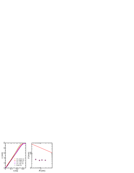
It appears that scales linearly with time, as expected from the model in the short-time limit. In Fig. 2.b, the filling velocities (slope of the curves) for different radii are compared to the theoretical prediction of Eq. (9). The theoretical prediction fails to describe the numerical data both quantitatively (simulated velocities are much smaller than expected) and qualitatively: While the model predicts that should decrease as , the simulation shows that does not depend significantly on the tube radius.
While the quantitative discrepancy could be explained by a reduced surface tension (due to curvature and interaction with the surface), the invariance of with the radius seems to point toward another effect, for instance a drag force missing in the model. Even if viscosity is not expected to play a role inside the tube due to the very large slip length, its influence was nevertheless tested, using a Dissipative Particle Dynamics (DPD) thermostat Groot and Warren (1997). This amounts to adding pairwise interactions between atoms, with a dissipative force depending on the relative velocity between each pair and a random force with a Gaussian statistics. This method has the advantage of preserving hydrodynamics. Furthermore, the amplitude of the dissipative term can be tuned to modify the liquid viscosity without changing its static properties. The viscosity dependency on the dissipative term was carefully calibrated in independent simulations of shear flow of water between two silica surfaces (Fig. 3.a). For the largest dissipative terms, the timestep had to be reduced down to 0.5 fs.
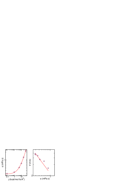
The filling velocity was then measured for a given CNT, with radius 1.87 nm, varying the viscosity of the DPD-thermostated-water. On Fig. 3.b, one can observe a clear influence of viscosity on the filling velocity. Due to the very large slip length of water inside CNT, friction at the wall should be completely negligible for the filling lengths simulated. Moreover, in such a plug-flow regime, the liquid moves as a block everywhere inside the tube. Therefore, there should be no dissipation near the contact line, and consequently no dynamical change of the contact angle. Yet, even in the absence of friction inside the tube, viscous dissipation can occur at the tube entrance due to the contraction of the streamlines Sampson (1891); Johansen (1930); Weissberg (1962); van Nierop et al. (2008, 2009); Thomas and McGaughey (2009); Sisan and Lichter (2011). The power dissipated by viscosity can be estimated as: . The only length scale related to the entrance of the liquid inside the tube is the tube radius, hence: . Neglecting the kinetic energy of the liquid (inertial term): , the viscous dissipation must be equal to the power of the driving capillary force: . Finally . Therefore, if the filling is controlled by viscous dissipation at the entrance, the velocity should not depend on the tube radius (as observed in Fig. 2.b), and scale with the inverse of viscosity. One can check in Fig. 3 that the numerical results for versus are correctly fitted with an inverse function. To conclude, MD simulations show that, for water filling CNTs, inertia is negligible with regard to viscous dissipation at the entrance. The standard description of capillary filling presented earlier must thus be modified.
In this paragraph, a simple analytical description of the full capillary filling dynamics, taking into account entrance effects (but neglecting liquid inertia), will be presented. It will be restricted to the plug-flow limit (), which is relevant to the case of water inside CNTs, but could easily be generalized. The pressure drop along the liquid inside the tube is given by the Laplace pressure difference across the curved liquid/vapor meniscus, minus the pressure drop at the tube entrance Sampson (1891): . If we neglect liquid inertia, the corresponding velocity in the plug-flow regime is: . The resulting equation:
| (13) |
can be integrated into:
| (14) |
This simple quadratic equation admits the following solution:
| (15) |
where:
| (16) |
and:
| (17) |
For , the full solution (15) simplifies to give a filling at constant velocity , which is compatible with the simple dimensional analysis presented above. For it reduces to Eq. (12). Interestingly, even in the plug-flow limit, the transition length between the two regimes provides a direct measure of the slip length (Eq. 17). Furthermore, for slip lengths of a few hundredth of nanometers Holt et al. (2006); Falk et al. (2010), would lie within the micrometer range.
IV Conclusion
In this article, the consequences of the giant slip of water inside carbon nanotubes on the dynamics of capillary filling have been investigated. It has been shown that in case the slip length is much larger than the tube radius (plug-flow limit), viscosity does not play a role, and the relevant physical parameter controlling the flow is the liquid/solid friction coefficient. Moreover, scaling of the various quantities as a function of the tube radius are modified. It was then shown, using MD simulations, that in the short-time limit the filling velocity is not limited by the liquid inertia, but rather by viscous dissipation at the tube entrance. A model of the full capillary filling dynamics, taking into account entrance effects (but neglecting liquid inertia) was finally presented.
Generally, friction of water inside CNT is so small that for any real flow experiments, one can expect that the hydrodynamic resistance at the tube input and output will play a significant role Sisan and Lichter (2011). It could even contribute much more strongly to the total pressure drop than the friction inside the tube. In any case, measurement of flow rate versus pressure drop for CNTs of a given length can only give a higher limit for the friction coefficient inside the tube, so that measurements with different tube lengths could prove necessary.
Acknowledgements.
LJ thanks A.-L. Biance, L. Bocquet, K. Falk, S. Merabia, and O. Pierre-Louis for sharing data and/or for useful exchanges. This work was funded by the MIKADO grant of the French Agence Nationale de la Recherche.References
- de Gennes et al. (2003) P. G. de Gennes, F. Brochard-Wyart, and D. Quere, Capillarity and Wetting Phenomena: Drops, Bubbles, Pearls, Waves (Springer, 2003).
- Zhmud et al. (2000) B. V. Zhmud, F. Tiberg, and K. Hallstensson, “Dynamics of capillary rise,” J. Colloid Interface Sci., 228, 263 (2000).
- Lucas (1918) R. Lucas, “The time law of the capillary rise of liquids.” Kolloid Z., 23, 15 (1918).
- Washburn (1921) E. W. Washburn, “The dynamics of capillary flow.” Physical Review, 17, 273 (1921).
- Bosanquet (1923) C. H. Bosanquet, “On the flow of liquids into capillary tubes.” Philos. Mag., 45, 525 (1923).
- Quere (1997) D. Quere, “Inertial capillarity,” Europhys. Lett., 39, 533 (1997).
- Stange et al. (2003) M. Stange, M. E. Dreyer, and H. J. Rath, “Capillary driven flow in circular cylindrical tubes,” Phys. Fluids, 15, 2587 (2003).
- Schoch et al. (2008) R. B. Schoch, J. Y. Han, and P. Renaud, “Transport phenomena in nanofluidics,” Reviews of Modern Physics, 80, 839 (2008).
- Sparreboom et al. (2009) W. Sparreboom, A. van den Berg, and J. C. T. Eijkel, “Principles and applications of nanofluidic transport,” Nature Nanotechnology, 4, 713 (2009).
- Bocquet and Charlaix (2010) L. Bocquet and E. Charlaix, “Nanofluidics, from bulk to interfaces,” Chemical Society Reviews, 39, 1073 (2010).
- Bocquet and Barrat (2007) L. Bocquet and J. L. Barrat, “Flow boundary conditions from nano- to micro-scales,” Soft Matter, 3, 685 (2007).
- Marmur (1988) A. Marmur, “Penetration of a small drop into a capillary,” J. Colloid Interface Sci., 122, 209 (1988).
- Martic et al. (2004) G. Martic, F. Gentner, D. Seveno, J. De Coninck, and T. D. Blake, “The possibility of different time scales in the dynamics of pore imbibition,” J. Colloid Interface Sci., 270, 171 (2004).
- Supple and Quirke (2004) S. Supple and N. Quirke, “Molecular dynamics of transient oil flows in nanopores i: Imbibition speeds for single wall carbon nanotubes,” J. Chem. Phys., 121, 8571 (2004).
- Dimitrov et al. (2007) D. I. Dimitrov, A. Milchev, and K. Binder, “Capillary rise in nanopores: Molecular dynamics evidence for the Lucas-Washburn equation,” Phys. Rev. Lett., 99, 054501 (2007).
- Huber et al. (2007) P. Huber, S. Gruner, C. Schafer, K. Knorr, and A. V. Kityk, “Rheology of liquids in nanopores: A study on the capillary rise of water, n-hexadecane and n-tetracosane in mesoporous silica,” European Physical Journal-special Topics, 141, 101 (2007).
- Cupelli et al. (2008) C. Cupelli, B. Henrich, T. Glatzel, R. Zengerle, M. Moseler, and M. Santer, “Dynamic capillary wetting studied with dissipative particle dynamics,” New Journal of Physics, 10, 043009 (2008).
- Schebarchov and Hendy (2008) D. Schebarchov and S. C. Hendy, “Dynamics of capillary absorption of droplets by carbon nanotubes,” Physical Review E, 78, 046309 (2008).
- Gruener et al. (2009) S. Gruener, T. Hofmann, D. Wallacher, A. V. Kityk, and P. Huber, “Capillary rise of water in hydrophilic nanopores,” Physical Review E, 79, 067301 (2009).
- Ahadian et al. (2010) S. Ahadian, H. Mizuseki, and Y. Kawazoe, “On the kinetics of the capillary imbibition of a simple fluid through a designed nanochannel using the molecular dynamics simulation approach,” J. Colloid Interface Sci., 352, 566 (2010).
- Chen et al. (2010) C. Chen, C. N. Gao, L. Zhuang, X. F. Li, P. C. Wu, J. F. Dong, and J. T. Lu, “A many-body dissipative particle dynamics study of spontaneous capillary imbibition and drainage,” Langmuir, 26, 9533 (2010).
- Stukan et al. (2010) M. R. Stukan, P. Ligneul, J. P. Crawshaw, and E. S. Boek, “Spontaneous imbibition in nanopores of different roughness and wettability,” Langmuir, 26, 13342 (2010).
- Wu et al. (2010) K. F. Wu, B. Zhou, P. Xiu, W. P. Qi, R. Z. Wan, and H. P. Fang, “Kinetics of water filling the hydrophobic channels of narrow carbon nanotubes studied by molecular dynamics simulations,” J. Chem. Phys., 133, 204702 (2010).
- Phan et al. (2010) V. N. Phan, N. T. Nguyen, C. Yang, P. Joseph, L. Djeghlaf, D. Bourrier, and A. M. Gue, “Capillary filling in closed end nanochannels,” Langmuir, 26, 13251 (2010).
- Schebarchov and Hendy (2011) D. Schebarchov and S. C. Hendy, “Uptake and withdrawal of droplets from carbon nanotubes,” Nanoscale, 3, 134 (2011).
- Qin et al. (2011) X. C. Qin, Q. Z. Yuan, Y. P. Zhao, S. B. Xie, and Z. F. Liu, “Measurement of the rate of water translocation through carbon nanotubes,” Nano Letters, 11, 2173 (2011).
- Majumder et al. (2005) M. Majumder, N. Chopra, R. Andrews, and B. J. Hinds, “Nanoscale hydrodynamics - enhanced flow in carbon nanotubes,” Nature, 438, 44 (2005).
- Holt et al. (2006) J. K. Holt, H. G. Park, Y. M. Wang, M. Stadermann, A. B. Artyukhin, C. P. Grigoropoulos, A. Noy, and O. Bakajin, “Fast mass transport through sub-2-nanometer carbon nanotubes,” Science, 312, 1034 (2006).
- Whitby et al. (2008) M. Whitby, L. Cagnon, M. Thanou, and N. Quirke, “Enhanced fluid flow through nanoscale carbon pipes,” Nano Lett., 8, 2632 (2008).
- Du et al. (2011) F. Du, L. T. Qu, Z. H. Xia, L. F. Feng, and L. M. Dai, “Membranes of vertically aligned superlong carbon nanotubes,” Langmuir, 27, 8437 (2011).
- Thomas and McGaughey (2008) J. A. Thomas and A. J. H. McGaughey, “Reassessing fast water transport through carbon nanotubes,” Nano Lett., 8, 2788 (2008).
- Falk et al. (2010) K. Falk, F. Sedlmeier, L. Joly, R. R. Netz, and L. Bocquet, “Molecular origin of fast water transport in carbon nanotube membranes: Superlubricity versus curvature dependent friction,” Nano Lett., 10, 4067 (2010).
- Humphrey et al. (1996) W. Humphrey, A. Dalke, and K. Schulten, “VMD – Visual Molecular Dynamics,” J. Molec. Graphics, 14, 33 (1996), http://www.ks.uiuc.edu/Research/vmd/ .
- Alexiadis and Kassinos (2008) A. Alexiadis and S. Kassinos, “Molecular simulation of water in carbon nanotubes,” Chemical Reviews, 108, 5014 (2008).
- Werder et al. (2003) T. Werder, J. H. Walther, R. L. Jaffe, T. Halicioglu, and P. Koumoutsakos, “On the water-carbon interaction for use in molecular dynamics simulations of graphite and carbon nanotubes,” J. Phys. Chem. B, 107, 1345 (2003).
- Kolesnikov et al. (2004) A. I. Kolesnikov, J. M. Zanotti, C. K. Loong, P. Thiyagarajan, A. P. Moravsky, R. O. Loutfy, and C. J. Burnham, “Anomalously soft dynamics of water in a nanotube: A revelation of nanoscale confinement,” Phys. Rev. Lett., 93, 035503 (2004).
- Cambré et al. (2010) S. Cambré, B. Schoeters, S. Luyckx, E. Goovaerts, and W. Wenseleers, “Experimental Observation of Single-File Water Filling of Thin Single-Wall Carbon Nanotubes Down to Chiral Index (5,3),” Phys. Rev. Lett., 104, 207401 (2010).
- Kyakuno et al. (2011) H. Kyakuno, K. Matsuda, H. Yahiro, Y. Inami, T. Fukuoka, Y. Miyata, K. Yanagi, Y. Maniwa, H. Kataura, T. Saito, M. Yumura, and S. Iijima, “Confined water inside single-walled carbon nanotubes: Global phase diagram and effect of finite length,” J. Chem. Phys., 134, 244501 (2011).
- Pascal et al. (2011) T. A. Pascal, W. A. Goddard, and Y. Jung, “Entropy and the driving force for the filling of carbon nanotubes with water,” PNAS, 108, 11794 (2011).
- van Honschoten et al. (2010) J. W. van Honschoten, N. Brunets, and N. R. Tas, “Capillarity at the nanoscale,” Chem. Soc. Rev., 39, 1096 (2010).
- Cornell et al. (1995) W. D. Cornell, P. Cieplak, C. I. Bayly, I. R. Gould, K. M. Merz, D. M. Ferguson, D. C. Spellmeyer, T. Fox, J. W. Caldwell, and P. A. Kollman, “A 2nd generation force-field for the simulation of proteins, nucleic-acids, and organic-molecules,” J. Am. Chem. Soc., 117, 5179 (1995).
- Vega and de Miguel (2007) C. Vega and E. de Miguel, “Surface tension of the most popular models of water by using the test-area simulation method,” J. Chem. Phys., 126, 154707 (2007).
- Gonzalez and Abascal (2010) M. A. Gonzalez and J. L. F. Abascal, “The shear viscosity of rigid water models,” J. Chem. Phys., 132, 096101 (2010).
- Plimpton (1995) S. Plimpton, “Fast parallel algorithms for short-range molecular-dynamics,” J. Comput. Phys., 117, 1 (1995), http://lammps.sandia.gov/ .
- Thomas and McGaughey (2009) J. A. Thomas and A. J. H. McGaughey, “Water flow in carbon nanotubes: Transition to subcontinuum transport,” Phys. Rev. Lett., 102, 184502 (2009).
- Groot and Warren (1997) R. D. Groot and P. B. Warren, “Dissipative particle dynamics: Bridging the gap between atomistic and mesoscopic simulation,” J. Chem. Phys., 107, 4423 (1997).
- Sampson (1891) R. A. Sampson, “On stokes’s current function,” Phil. Trans. R. Soc. Lond. A, 182, 449 (1891).
- Johansen (1930) F. C. Johansen, “Flow through pipe orifices at low reynolds numbers,” Proc. R. Soc. Lond. A, 126, 231 (1930).
- Weissberg (1962) H. L. Weissberg, “End correction for slow viscous flow through long tubes,” Physics of Fluids, 5, 1033 (1962).
- van Nierop et al. (2008) E. A. van Nierop, B. Scheid, and H. A. Stone, “On the thickness of soap films: an alternative to Frankel’s law,” Journal of Fluid Mechanics, 602, 119 (2008).
- van Nierop et al. (2009) E. A. van Nierop, B. Scheid, and H. A. Stone, “On the thickness of soap films: an alternative to Frankel’s law - corrigendum,” Journal of Fluid Mechanics, 630, 443 (2009).
- Sisan and Lichter (2011) T. B. Sisan and S. Lichter, “The end of nanochannels,” Microfluid. Nanofluid., 11, 787 (2011).