Dilution and resonance enhanced repulsion in non-equilibrium fluctuation forces
Abstract
In equilibrium, forces induced by fluctuations of the electromagnetic field between electrically polarizable objects (microscopic or macroscopic) in vacuum are always attractive. The force may, however, become repulsive for microscopic particles coupled to thermal baths with different temperatures. We demonstrate that this non-equilibrium repulsion can be realized also between macroscopic objects, as planar slabs, if they are kept at different temperatures. It is shown that repulsion can be enhanced by (i) tuning of material resonances in the thermal region, and by (ii) reducing the dielectric contrast due to “dilution”. This can lead to stable equilibrium positions. We discuss the realization of these effects for aerogels, yielding repulsion down to sub-micron distances at realistic porosities.
pacs:
12.20.-m, 44.40.+a, 05.70.LnForces induced by electromagnetic (EM) field fluctuations of quantum and thermal origin act virtually between all matter that couples to the EM field, since the interacting objects need not to be charged parsegian_book ; bordag . Under rather general conditions (e. g., for non-magnetic objects in vacuum), the Casimir potential energy does not allow for stable equilibrium positions of the interacting objects Rahi+10 . This can be a practical disadvantage in systems where external (non-fluctuation) forces cannot be applied or fine-tuned to establish stability, especially in dynamic systems where the distance and hence the Casimir force changes in time. Nano-mechanical devices with closely spaced components fall into this class of systems Serry+95 . Repulsive Casimir forces are known to exist if the space between the objects is filled by a dielectric with suitable contrast DLP61 , but this is impractical in many situations.
Repulsion can occur also in response to the preparation of particles in distinct internal states, e.g. by optical excitation or coupling to heat baths of different temperatures. In particular, Cohen and Mukamel cohen predicted a non-equilibrium repulsive force between molecules generated by suitable detuning of the resonance frequencies. This suggests that for macroscopic objects held at different temperatures similar repulsive effects should exist close to material resonances in the thermal region. However, for macroscopic condensates the dielectric contrast is usually strong and non-equilibrium effects are comparatively less significant than the equilibrium attraction. One should thus focus on sufficiently optically diluted materials to generate resonant Casimir repulsive forces between macroscopic bodies. The general formalism for dealing with non-equilibrium fluctuation effects between macroscopic bodies has been developed recently in pita ; bimonte ; Krueger+11 ; antezza ; Krueger+111 .
The aim of the present work is to explore theoretically if and to what extent the above expectation can be realized and whether it can lead to stable equilibrium positions. We consider two dielectric slabs held at different temperatures, and computed the pressure between them using the non-equilibrium extension of the Casimir–Lifshitz formula pita . Employing a Lorentz-Drude dielectric response, we find that resonances and optical dilution indeed amplify repulsion sufficiently so that the total interaction can become repulsive, and equilibrium positions exist. We show that aerogels could be used to realize resonant repulsion in practice since porosity can be used to tune reflectivity and resonances. The use of aerogels was indeed previously proposed to reduce the Casimir force esquivel07 , but not to generate repulsion.
We consider two infinite parallel planar slabs , each consisting of a non-magnetic dielectric layer of thickness and permittivity , deposited on a thick glass substrate of dielectric permittivity . The slabs are held at temperatures and , separated by a (vacuum) gap of width . The Casimir pressure acting on the inside faces of the plates is given by pita
| (1) |
where is the Stefan-Boltzmann constant. The last term in this equation is simply the classical thermal radiation result, which is independent of distance and material properties. In Eq. (1), denotes the average of the equilibrium Casimir pressures at and ; with given by the Lifshitz formula lifs , which for brevity is not reproduced here. The novel non-equilibrium contributions are captured by the term , which vanishes for (it also contains a distance independent part). Upon decomposing into propagating waves (PW) and evanescent waves (EW), one finds 111We use a sign convention opposite to Ref. pita , such that negative pressures represent attraction between the slabs.
| (2) | |||
| (3) |
where , , , and for the two polarizations. The reflection coefficients are given by the well-known formulae for a two-layer slab
| (4) |
where are the Fresnel reflection coefficients
| (5) |
where , and is obtained by replacing the and in Eq. (5) by one (but not in ). There is also an external pressure acting on the outside face of each plate which depends on the reflectivity of this face and the temperature of the environment . In our numerical computations we assume that the external face of the glass substrate has been blackened, in which case the total pressure on plate is given by
| (6) |
It is worth emphasizing that for , . Also, in equilibrium all distance independent terms vanish.
The structure of the non-equilibrium force in Eq. (1) suggests that repulsion should exist out of thermal equilibrium. While the first term in Eq. (1) is bound to be attractive, this is not so for the second term . As it can be seen from Eqs. (2) and (3), the quantity changes sign if the temperatures and are exchanged, and therefore its sign can be reversed by simply switching the temperatures of the plates. One notes also that is antisymmetric under the exchange , and vanishes for . Therefore in order to take advantage of this term to control the sign of the Casimir force it is mandatory to consider plates made of different materials. For real materials, both and diverge as if . In the following, we show that the sign of this asymptotic behavior can be made repulsive in certain cases.
Motivated by the resonance-induced repulsion for microscopic particles, we consider electric permittivities of the dielectric layers described by a Lorentz-Drude type model, as
| (7) |
(An analogous two-oscillator model was used also for the permittivity of the glass substrate, with the parameters quoted in bordag .) The first oscillator term () describes low-lying excitations of the materials; such low-lying polariton excitations in numerous dielectrics account for sharp peaks in their dielectric functions in the far infrared region. Typical values for the resonance and relaxation frequencies are rad/sec and rad/sec Kittel . The second oscillator term in Eq. (7), proportional to , describes the contribution of core electrons. Excitation energies of core electrons are much larger, and characteristic values of are in the range rad/sec. At and around room temperature core electrons are not thermally excited (for K the characteristic thermal frequency is 3.9 rad/sec) and therefore their contribution to the thermal Casimir force is very small. However core electrons are important, as they strongly contribute to the average equilibrium Casimir force , especially at sub-micron separations.
Since the thermal Casimir force between two macroscopic slabs should reduce in the dilute limit to the pairwise interaction between their atoms, one expects that the resonant phenomena reported in Ref. cohen should be recovered if the material of the plates is sufficiently diluted. In order to determine how large a dilution is necessary for this to happen, we investigated the behavior of the Casimir force under a rescaling of the amplitudes of the resonance peaks, i.e. , by a overall optical dilution parameter .
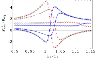
We next report on numerical results based upon the above model for dielectrics, in which we set , , , and (all in rad/sec). In Fig. 1 we plot the non-equilibrium normalized Casimir pressure on slab 2 versus the ratio of the resonance frequencies , for nm, m, , , , and . (Negative values of correspond to repulsion.) For these parameters the non-equilibrium force is dominated by evanescent waves, whose skin depth is comparable to the separation . This implies that for separations the force is practically independent of , but for the features of the substrate influence the magnitude of the force significantly. The red dashed curves in Fig. 1 are for K and K, while blue solid curves are for K and K. Three values of the dilution parameter are displayed: (), (+) and (). We see that for sufficiently high dilution, the Casimir force is strongly dependent on the ratio of the resonance frequencies of the plates, displaying features analogous to those reported in Ref. cohen for the van der Waals interaction between two ‘atoms’ coupled to baths at different temperatures. In particular, the Casimir force becomes repulsive if this ratio is suitably tuned to a value close to unity. We also find that the equilibrium force is rather insensitive to the tuning of resonances, and that the total force hardly depends on .
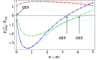
In Fig. 2 we plot the dependence of the non-equilibrium normalized Casimir pressure on slab 2, as a function of plate separation , at K, K, for and (); and (+); and (), all other parameters being same as in Fig. 1. The dashed curves do not include the distance independent part of the pressure, and are included to indicate that this component also changes sign upon dilution. We see that without dilution () the non-equilibrium Casimir force is attractive for all displayed separations. By contrast, for large enough dilutions and for suitable values of , the force becomes repulsive in a wide range of separations. The curve for exhibits two points of zero force, one at nm and another for m, corresponding to an unstable equilibrium point (UEP) and a stable equilibrium point (SEP), respectively. For there is a single turning point corresponding to a SEP at m. There is no UEP point in this case as the ratio approaches a negative value in the limit , signifying that repulsion persists for arbitrarily small plate separations less than the SEP.
As a means of achieving the dilution levels required to observe the resonance phenomena described above, we consider aerogels: highly porous materials fabricated by sol-gel techniques, starting from a variety of materials such as , carbon, , platinum etc. Aerogels with levels of porosity exceeding 99 can be realized nowadays Pierre . In order to study the Casimir force between two aerogel plates we need an expression for the dielectric function of the aerogel, valid in the wide range of frequencies relevant for the Casimir effect. For separations larger than the pore size (typically of the order of 100 nm or less), an effective medium approach can be used in which the aerogel permittivity is obtained from the Maxwell-Garnett equation Choy_book as
| (8) |
Here, is the permittivity of the solid fraction of the aerogel, and is the porosity. Equation (8) is justified if the solid fraction is well separated by the host material (air), i.e., when is sufficiently close to one. Using again a model of the form in Eq. (7) for , one finds that has a resonance at the frequency
| (9) |
where we assumed . According to Eq. (9), the frequency of the aerogel resonance is blue-shifted with respect to , and as is varied from zero to one, sweeps the range from to . The dependence of the resonance frequency on the porosity is welcome, because it gives us the possibility of tuning the ratio of the resonance frequencies for the two plates by simply choosing appropriate values for the porosities and of the plates.
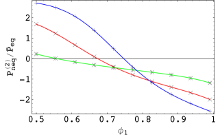
As an example, we consider two aerogel layers of thickness m, deposited on a thick glass substrate, with a blackened outer surface. The dielectric functions of the host materials are as in Eq. (7), with , , , =0.84. In Fig. 3 we plot the ratio as a function of the porosity of the first plate. The porosity of the second plate is 0.95 (+), 0.9 () and 0.8 (). All curves in Fig. 3 are for a separation of 200 nm, at K and K. The force can indeed be made repulsive by suitably adjusting the porosities of the two plates. In absolute terms, the Casimir force is small; e.g. for and we find Pa.
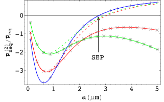
In Fig. 4 we plot dependence of the ratio on the separation (in microns), for and =0.95 (+), =0.9 () and =0.8 (). All parameters for the aerogel plates are the same as in Fig. 3. The dashed lines do not include the separation independent part of the pressure. We find that for a stable equilibrium point exists (marked as SEP in Fig. 4).
While fluctuation induced forces are generally attractive, repulsive forces can be obtained between atoms prepared in different excited states. Coupling of atoms to thermal baths at different temperatures can in principle produce population of states that lead to repulsion. We show that a similar non-equilibrium repulsive contribution to pressure also arises from the interplay of resonances for two macroscopic slabs held at appropriate distinct temperatures. However, to observe a net repulsion between slabs one must overcome an ever present attractive force arising from the dielectric contrast of the condensed bodies from the intervening vacuum. The latter can be reduced by dilution, and we have shown that aerogels provide a material where a net repulsion at sub-micron separations can be achieved, leading to a stable equilibrium point.
This research was supported by the ESF Research Network CASIMIR, DARPA contract No. S-000354, DFG grant No. KR 3844/1-1 and NSF Grant No. DMR-08-03315. We have benefitted from discussions with R.L. Jaffe, M.F. Maghrebi, U. Mohideen, and R. Zandi.
References
- (1) V. A. Parsegian, Van der Waals Forces (Cambridge University Press, 2006).
- (2) M. Bordag, G. L.Klimchitskaya, U. Mohideen, and V. M. Mostepanenko, Advances in the Casimir Effect (Oxford University Press, Oxford, 2009).
- (3) I. E. Dzyaloshinskii, E. M. Lifshitz, L. P. Pitaevskii, Adv. Phys. 10, 165 (1961).
- (4) S. J. Rahi, M. Kardar, T. Emig, Phys. Rev. Lett. 105, 070404 (2010).
- (5) F. M. Serry, D. Walliser, and G. J. Maclay, J. Microelectromech. Syst. 4, 193 (1995); J. Appl. Phys. 84, 2501 (1998).
- (6) A.E. Cohen and S. Mukamel, Phys. Rev. Lett. 91, 233202 (2003).
- (7) M. Antezza, L.P. Pitaevskii, S. Stringari and V.B. Svetovoy, Phys. Rev A 77, 022901 (2008).
- (8) G. Bimonte, Phys. Rev. A 80, 042102 (2009).
- (9) M. Krüger, T. Emig, M. Kardar, Phys. Rev. Lett. 106, 210404 (2011).
- (10) R. Messina and M. Antezza, arXiv:1103.2668.
- (11) M. Krüger, T. Emig, G. Bimonte, and M. Kardar, Europhys. Lett. 95, 21002 (2011).
- (12) R. Esquivel-Sirvent, J. Appl. Phys. 102, 034307 (2007).
- (13) C. Henkel, K. Joulain, J-P Mulet, and J-J Greffet, J. Opt.A: Pure Appl. Opt. 4, S109 (2002).
- (14) E.M. Lifshitz, Sov. Phys. JETP 2, 73 (1956); E.M. Lifshitz and L.P. Pitaevskii, Landau and Lifshitz Course of Theoretical Physics: Statistical Physics Part II (Butterworth-Heinemann, 1980)
- (15) C. Kittel, Introduction to Solid State Physics (Wiley, 2005)
- (16) A. C. Pierre, and G. M. Pajonk, Chem. Rev. 102, 4243 (2002).
- (17) T. C. Choy, Effective Medium Theory (Oxford: Clarendon Press, 1999)