Low energy graphene edge termination via small diameter nanotube formation
Abstract
We demonstrate that free graphene sheet edges can curl back on themselves, reconstructing as nanotubes. This results in lower formation energies than any other non-functionalised edge structure reported to date in the literature. We determine the critical tube size and formation barrier and compare with density functional simulations of other edge terminations including a new reconstructed Klein edge. Simulated high resolution electron microscopy images show why such rolled edges may be difficult to detect. Rolled zigzag edges serve as metallic conduction channels, separated from the neighbouring bulk graphene by a chain of insulating sp3-carbon atoms, and introduce Van Hove singularities into the graphene density of states.
The atomic structure of graphene and graphene edges, is a subject of great interest, in particular stimulated by new aberration corrected atomic resolution electron microscopy studies Jia et al. (2011); Girit et al. (2009). Edge structure can define the chemical and electronic properties of graphene ribbons Enoki et al. (2007); *kunstmann2011stability; *wassmann2008structure, yet there is no consensus about the most stable free edge structure. Unterminated edges, consisting in a line of atoms with dangling bonds, are inherently unstable and subject to chemical functionalisation in ambient. However under vacuum conditions, such as in electron microscope columns, unterminated edges can be observed. Simply cutting through the graphene lattice results in the most studied edge structures: armchair or zigzag, or a combination of the two. The first way that free edges can stabilise themselves is via rehybridisation of the carbon atoms. This occurs spontaneously for the armchair edge giving a sequence of double bonds along the edge. The zigzag edge has been shown to be also metastable and undergo a 5-7 reconstruction Koskinen et al. (2008), which has been recently experimentally confirmed Koskinen et al. (2009); *chuvilin2009graphene. High resolution transmission electron microscopy (HRTEM) suggests that alternative edge structures may be also common, including the theoretically less stable zigzag and Klein edges Liu et al. (2009); Warner et al. (2009); Huang et al. (2009); Girit et al. (2009); Gass et al. (2008); Meyer et al. (2007a); Rotkin and Gogotsi (2002). Other reconstructed edges, loosely based on the Haeckelite structures Terrones et al. (2000) have also been proposed Jia et al. (2011). Besides reconstruction, HRTEM Liu et al. (2009); Warner et al. (2010, 2009); Huang et al. (2009); Girit et al. (2009); Gass et al. (2008); Meyer et al. (2007a); Rotkin and Gogotsi (2002); Meyer et al. (2007b) has shown that free edges can fold back on themselves resulting in no longer a graphene monolayer (so-called grafold Kim et al. (2011)). The energetic cost of bending the layer is partially compensated by Van der Waals interactions in the stacked region.
In this Letter we extend the range of edge types, introducing a third type of stabilised edge whereby edges are rolled back on themselves and rebonded into the graphene sheet. This results in a graphene monolayer with nanotube at the edge site, and eliminates all dangling bonds by sp3-like rehybridisation of the carbon atoms along the rebonding line.
We perform spin polarized density functional calculations under the local density approximation using the AIMPRO code Jones and Briddon (1998); *Aimp-2; *Aimp-3. Graphene edges are modeled using ribbons with width 50Å in orthogonal supercells large enough to avoid interaction between neighbouring cells. Tubular rolled edges were created symmetrically on both of the two ends of the graphene ribbon. Edge formation energies per unit length (eV/Å) are determined via
where Etot is the total internal energy of a system with carbon atoms, is the energy of a carbon atom in a perfect graphene sheet and is the ribbon edge length. Reaction barriers were calculated using the climbing nudged elastic band technique Mills and Jønnson (1994), with all atoms allowed to move. More details are given in the supplementary materials.
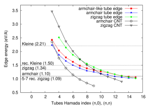
We begin by considering formation energies for zigzag, armchair, 5-7 reconstructed zigzag, KleinKlein (1994) and reconstructed Klein edges (Fig. 1 and supplementary materials). In all cases no out of plane distortion (e.g. edge rippling) was found after relaxation. In agreement with results of Ref. Koskinen et al. (2008), we obtain the armchair and 5-7 reconstructed zigzag edges to be the most energetically stable. The least stable is the Klein edge with unsaturated carbon atoms, however if symmetry is allowed to break, it spontaneously reconstructs by rebonding in pairs, gaining 0.7 eV/Å (see supplementary materials). Segments of unreconstructed Klein edge were recently observed by annular dark field microscopy Liu et al. (2009); Suenaga and Koshino (2010) but the observed Klein edges might have residual hydrogen not detectable by annular dark field microscopy.


A new type of termination leading to the stabilization of the edge can be achieved by taking an unreconstructed free edge, folding it back on itself and bonding the edge dangling bonds to a line of basal graphene atoms. A rolled zigzag edge can bond into the graphene plane in two configurations: either above what would be zigzag edge atoms or Klein edge atoms. Rolled armchair edges can only bond to equivalent armchair edge atoms. Drawing on nanotube nomenclature we refer to these new edges as armchair-nanotube terminated (Fig. 2a), armchair-like nanotube terminated (Fig. 2b), and zigzag-nanotube terminated (Fig. 2c) respectively. In all cases the line of carbon atoms bridging the tube and graphene layer adopts an sp3-like hybridization with average bond lengths (Å) and angles () close to those of diamond. Locally, the structure is similar to the core of the zigzag prismatic dislocation in AA graphite Suarez-Martinez et al. (2007). The sp3-like bonding allows the tube to localise strain, resulting in a droplet-shaped cross-section (Fig. 2).
Fig. 1 presents formation energies for different types of free and tube terminated edges as a function of the Hamada index of the tube. For comparison we plot the values for free-standing armchair and zigzag tubes. Consistent with an earlier study Sawada and Hamada (1992), free standing small tubes with diameters below 4 Å (i.e. (3,3) and (5,0) and below) are unstable compared to a flat graphene sheet. This means that it is thermodynamically preferable to split these tubes open, even with unfunctionalised edges. Indeed experimentally these small radii nanotubes have not been observed on their own but they can exist as inner tubes in large multiwalled nanotubes Qin et al. (2000); *guan2008smallest. We see here however that such small nanotubes are more stable when formed on graphene ribbon edges, through localisation of the nanotube strain along the sp3-coordinated tetrahedral bonding line, e.g. a (3,3) armchair tube and all zigzag tubes up to (7,0). Comparing to free zigzag, edges become more stable when rolled in tubes above (8,8). Rolled armchair edges have a lower energy than free edges when forming nanotubes larger than (14,0). For the largest presented tube terminated edges, formation energies are lower than any of the previously proposed free edge configurations.
If we extrapolate to larger diameter tubes we might expect that they collapse due to Van der Waals interactions between walls to a dog-bone cross-section Chopra et al. (1995). However the droplet cross-section induced by the line of sp3-like carbon atoms naturally induces a “local collapse”, and this pinched region extends further as the tube diameter increases. Thus for large diameters, rolled edges converge to a classical folded edge which then terminates some distance from the actual edge via a line of sp3-like bonds. We note that in no case is the combination of a free tube and graphene edge more stable than the nanotube terminated edge Chernozatonskii et al. (2009) i.e. there will be no thermodynamic driving force for nanotube production from rolled edges.
We next examined the barrier to roll up the edges, determining the barrier between the free zigzag edge and an armchair-nanotube terminated edge as a function of the final tube size. For a (4,4) nanotube terminated edge, we find an NEB barrier for ribbon rolling of about 2 eV/Å, with a corresponding unrolling barrier of 0.9 eV/Å. For a (8,8) nanotube terminated edge barriers change to 1.3 eV/Å to roll versus 1.6 eV/Å for derolling. Increasing further the tube diameter gives tube reconstructed edges more stable than free edges and this induces a barrier height inversion. In particular for small tubes these barriers are quite high, due to the high curvature that has to be induced. However these represent maximum barriers and experimental barriers will likely be much smaller, since our calculations assume concerted simultaneous bonding/debonding along the entire edge length. Similar to dislocation motion, which proceeds via the propagation of kinks along the dislocation line rather than a concerted single-step motion, rolled edges will presumably roll/unroll initially at a single point which will then propagate along the nanotube length.
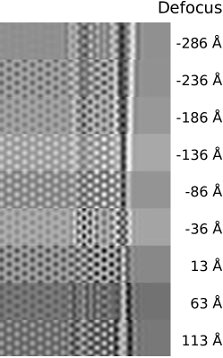
Given their low formation energies compared to free zigzag edges, we can ask the question why such tube terminated edges have not yet been reported in the literature. One reason is that these edges require long-range order, whereas other edge structures can vary over the order of single unit cells. Thus we may expect such edges to be more common in well defined periodic ribbon edges such as after splitting of large multi-walled nanotubes. We note also that free standing graphene can be obtained through wet etching after epitaxial growth on metal substrate Shivaraman et al. (2009). We expect that during the etching process rolled edges might appear as in analogous synthesis mechanisms used for the production of inorganic nanotubular materials Schmidt and Eberl (2001). Furthermore, rolled edges could be difficult to discriminate by transmission electron microscopy. Simulated HRTEM images (Fig. 2) are very similar to those of free standing edges, the primary difference being minor variations in the image contrast. Additionally these edges may display characteristic nanotube modes detectable using spatially resolved resonant Raman.
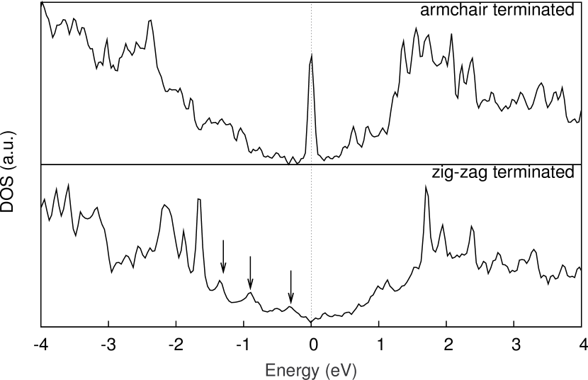
We next examine the effect of rolled edges on the electronic properties of the graphene. We present in Fig. 3 the electronic density of states for the (8,8) and (8,0) tube terminated edges. These show an interesting combination of the graphene and nanotube behaviour. In spite of different electronic character of free standing (8,8) and (8,0) tubes, i.e. metallic and semiconducting, in both cases the composite system has a non-zero density of states at the Fermi level. For a zigzag tube termination the background density of states around the Fermi level rises smoothly, reflecting the graphene density of states, overlaid on which there is a series of Van Hove singularities characteristic of a nanotube. For the armchair-tube terminated edge, i.e. a rolled zigzag graphene edge, there is a sharp peak at the Fermi level similar to that seen for flat unterminated zigzag edges Koskinen et al. (2008); Kunstmann et al. (2011). Such Fermi level peaks can lead to magnetic instability, and indeed our spin unrestricted calculations shows a ferromagnetic configuration to be the lowest energy state (slightly lowering of the edge energy of the system by only 0.02 eV/Å), although this must be treated with caution given the use of the local density approximation.

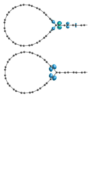
The peak consists of two degenerate states which can be seen in the associated band structure (Fig. 4a) as involving a mixing of several bands. Plotting these states at the and point (Fig. 4b) shows that the Fermi level spike is localised mainly on the row of graphene atoms next to the sp3-carbon atoms, mirroring the edge state seen in flat zigzag terminated graphene Enoki et al. (2007); *kunstmann2011stability; *wassmann2008structure, whereas at the -point the highest occupied state comes from dispersive edge states located in the nanotube segment along the junction. This convergence of three zigzag edges at the line of sp3-bonded carbon atoms suggests possible interesting magnetic behaviour under an applied field.
We note that the zigzag metallic edge state is preserved in this configuration, and unlike the unterminated simple zigzag edge it will also be partially protected from environmental attack, since all neighbouring atoms are fully coordinated. Notably we might expect it to be stable in air. These states also suggest intriguing transport behaviour, with possible conduction channels both along the edge of the graphene and in the edge states in the nanotube segment.
In summary we have shown that by rolling an unterminated graphene edge it is possible to create nanotube-terminated edges where the sheet edge rebonds back into the graphene plane. We determine the critical tube size and formation barriers and compare with density functional simulations of other edge terminations including a new reconstructed Klein edge. We find that the proposed tube terminated edges are more stable than any other non-functionalized edge structure, due to the replacement of dangling bonds with sp3-like hybridised carbon atoms. Rolled zigzag edges serve as metallic conduction channels, separated from the neighbouring bulk graphene by a chain of insulating sp3-carbon atoms, and introduce Van Hove singularities into the graphene density of states. They may provide a way to stabilise and protect from chemical attack the disperse Fermi level state seen along metallic zigzag edges. Similar edge rolling effects might also appear in other layered materials Coleman et al. (2011) such as boron nitride monolayers where orbital rehybridization can occur.
Acknowledgements.
This work has been carried out within the NANOSIM-GRAPHENE project nANR-09- NANO-016-01 funded by the French National Agency (ANR) in the frame of its 2009 programme in Nanosciences, Nanotechnologies and Nanosystems (P3N2009).References
- Jia et al. (2011) X. Jia, J. Campos-Delgado, M. Terrones, V. Meunier, and M. S. Dresselhaus, Nanoscale 3, 86 (2011).
- Girit et al. (2009) C. Girit, J. Meyer, R. Erni, M. Rossell, C. Kisielowski, L. Yang, C. Park, M. Crommie, M. Cohen, S. Louie, et al., Science 323, 1705 (2009).
- Enoki et al. (2007) T. Enoki, Y. Kobayashi, and K. Fukui, Int. Rev. Phys. Chem. 26, 609 (2007).
- Kunstmann et al. (2011) J. Kunstmann, C. Ozdoğan, A. Quandt, and H. Fehske, Phys. Rev. B 83, 045414 (2011).
- Wassmann et al. (2008) T. Wassmann, A. Seitsonen, A. Saitta, M. Lazzeri, and F. Mauri, Phys. Rev. Lett. 101, 96402 (2008).
- Koskinen et al. (2008) P. Koskinen, S. Malola, and H. Häkkinen, Phys. Rev. Lett. 101, 115502 (2008).
- Koskinen et al. (2009) P. Koskinen, S. Malola, and H. Häkkinen, Phys. Rev. B 80, 73401 (2009).
- Chuvilin et al. (2009) A. Chuvilin, J. Meyer, G. Algara-Siller, and U. Kaiser, New J. Phys. 11, 083019 (2009).
- Liu et al. (2009) Z. Liu, K. Suenaga, P. J. F. Harris, and S. Iijima, Phys. Rev. Lett. 102, 015501 (2009).
- Warner et al. (2009) J. H. Warner, F. Schäffel, M. H. Rümmeli, and B. Büchner, Chem. Mat. 21, 2418 (2009).
- Huang et al. (2009) J. Y. Huang, F. Ding, B. I. Yakobson, P. Lu, L. Qi, and J. Li, Proc. Natl. Acad. Sci. USA 106, 10103 (2009).
- Gass et al. (2008) M. Gass, U. Bangert, A. Bleloch, P. Wang, R. Nair, and A. Geim, Nat. Nanotechnol. 3, 676 (2008).
- Meyer et al. (2007a) J. Meyer, A. Geim, M. Katsnelson, K. Novoselov, T. Booth, and S. Roth, Nature 446, 60 (2007a).
- Rotkin and Gogotsi (2002) S. Rotkin and Y. Gogotsi, Mat. Res. Innov. 5, 191 (2002).
- Terrones et al. (2000) H. Terrones, M. Terrones, E. Hernández, N. Grobert, J. Charlier, and P. Ajayan, Phys. Rev. Lett. 84, 1716 (2000).
- Warner et al. (2010) J. Warner, M. H. Rümmeli, A. Bachmatiuk, and B. Büchner, Nanotechnology 21, 325702 (2010).
- Meyer et al. (2007b) J. C. Meyer, A. K. Geim, M. I. Katsnelson, K. S. Novoselov, D. Obergfell, S. Roth, C. Girit, and A. Zettl, Solid State Commun. 143, 101 (2007b).
- Kim et al. (2011) K. Kim, Z. Lee, B. Malone, K. T. Chan, B. Alemán, W. Regan, W. Gannett, M. F. Crommie, M. L. Cohen, and A. Zettl, Phys. Rev. B (2011), in Press.
- Jones and Briddon (1998) R. Jones and P. Briddon, Semicond. Semimetals 51A, 287 (1998).
- Rayson and Briddon (2008) M. Rayson and P. Briddon, Comput. Phys. Commun. 178, 128 (2008).
- Rayson and Briddon (2009) M. J. Rayson and P. R. Briddon, Phys. Rev. B 80, 205104 (2009).
- Mills and Jønnson (1994) G. Mills and H. Jønnson, Phys. Rev. Lett. 72, 1124 (1994).
- Klein (1994) D. Klein, Chem. Phys. Lett. 217, 261 (1994).
- Suenaga and Koshino (2010) K. Suenaga and M. Koshino, Nature 468, 1088 (2010).
- Suarez-Martinez et al. (2007) I. Suarez-Martinez, G. Savini, G. Haffenden, J. Campanera, and M. Heggie, Phys. Status Solidi C 4, 2958 (2007).
- Sawada and Hamada (1992) S. Sawada and N. Hamada, Solid State Commun. 83, 917 (1992).
- Qin et al. (2000) L. Qin, X. Zhao, K. Hirahara, Y. Miyamoto, Y. Ando, and S. Iijima, Nature 408, 50 (2000).
- Guan et al. (2008) L. Guan, K. Suenaga, and S. Iijima, Nano Lett. 8, 459 (2008).
- Chopra et al. (1995) N. Chopra, L. Benedict, V. Crespi, M. Cohen, S. Louie, and A. Zettl, Nature 377, 135 (1995).
- Chernozatonskii et al. (2009) L. Chernozatonskii, E. Sheka, and A. Artyukh, JETP Lett. , 352 (2009).
- Shivaraman et al. (2009) S. Shivaraman, R. Barton, X. Yu, J. Alden, L. Herman, M. Chandrashekhar, J. Park, P. McEuen, J. Parpia, H. Craighead, et al., Nano Lett. 9, 3100 (2009).
- Schmidt and Eberl (2001) O. Schmidt and K. Eberl, Nature 410, 168 (2001).
- Coleman et al. (2011) J. Coleman, M. Lotya, A. O’Neill, S. Bergin, P. King, U. Khan, K. Young, A. Gaucher, S. De, R. Smith, et al., Science 331, 568 (2011).
Appendix A Supplementary materials.
Computational Details
Structures were geometrically optimized using a () shifted k-point grid generated using the Monkhorst-Pack formalism. Hartwigsen, Goedecker and Hutter relativistic pseudopotentials were usedHartwigsen et al. (1998). Atom-centered Gaussian basis functions are used to construct the many-electron wave function with angular momenta up to l=2, i.e. 22 independent functions per C atom. We confirmed that all structures were energetically converged with respect to ribbon width by extending some of the calculations by another hexagon row, finding formation energy changes corresponding to the addition of bulk graphene atoms. Electronic level occupation was obtained using a Fermi occupation function with kT = 0.04 eV. Density of states calculations used a denser () k-point grid, with a 0.03 eV Gaussian broadening applied.
HRTEM image simulations
High resolution transmission electron microscopy (HRTEM) images were simulated using a full dynamical calculation by multislice method as implemented in the SimulaTEM program Gómez-Rodríguez et al. (2010). Formation energies and HREM image simulation for different edge types are presented in Fig. 5. A focal series for a (8,8) armchair rolled tube is presented in Fig. 6.
| Zigzag | Armchair | 5-7 reconstructed zigzag |
| 1.34 eV/Å | 1.10 eV/Å | 1.09 eV/Å |
| Klein edge | Reconstructed Klein edge | Reconstructed armchair |
| 2.21 eV/Å | 1.50 eV/Å | 1.63 eV/Å |
References
- Hartwigsen et al. (1998) C. Hartwigsen, S. Goedecker, and J. Hutter, Phys. Rev. B 58, 3641 (1998).
- Gómez-Rodríguez et al. (2010) A. Gómez-Rodríguez, L. Beltrán-del Río, and R. Herrera-Becerra, Ultramicroscopy 110, 95 (2010).