The biaxial nonlinear crystal BiB3O6 as a polarization entangled photon source using non-collinear type-II parametric down-conversion
A. Halevy,1 E. Megidish,1, L. Dovrat,1 H. S. Eisenberg,1 P. Becker,2 and L. Bohatý2
1Racah Institute of Physics, Hebrew University of Jerusalem,
Jerusalem 91904, Israel
2Institute of Crystallography, University of Cologne,
50939 Cologne, Germany
hagaie@huji.ac.il
Abstract
We describe the full characterization of the biaxial nonlinear crystal BiB3O6 (BiBO) as a polarization entangled photon source using non-collinear type-II parametric down-conversion. We consider the relevant parameters for crystal design, such as cutting angles, polarization of the photons, effective nonlinearity, spatial and temporal walk-offs, crystal thickness, and the effect of the pump laser bandwidth. Experimental results showing entanglement generation with high rates and a comparison to the well investigated -BaB2O4 (BBO) crystal are presented as well. Changing the down-conversion crystal of a polarization entangled photon source from BBO to BiBO enhances the generation rate as if the pump power was increased by 2.5 times. Such an improvement is currently required for the generation of multiphoton entangled states.
OCIS codes: (190.4400) Nonlinear optics, materials; (190.4410) Nonlinear optics, parametric processes; (260.1180) Crystal optics; (270.0270) Quantum optics; (270.5585) Quantum information and processing.
References and links
- [1] R. Ghosh and L. Mandel, “Observation of nonclassical effects in the interference of two photons,” Phys. Rev. Lett. 59, 1903–1905 (1987).
- [2] R. W. Boyd, Nonlinear Optics, edition (Academic Press, 2003).
- [3] P. G. Kwiat, K. Mattle, H. Weinfurter, A. Zeilinger, A. V. Sergienko, and Y. Shih, “New high intensity source of polarization-entangled photon pairs,” Phys. Rev. Lett. 75, 4337–4341 (1995).
- [4] P. Becker, “Borate materials in nonlinear optics,” Adv. Mater. 10, 979–992 (1998).
- [5] R. C. Eckardt, H. Masuda, Y. X. Fan, and R. L. Byer, “Absolute and relative nonlinear optical coefficients of KDP, KD∗P, BaB2O4, LiIO3, MgO:LiNbO3 and KTP measured by phase-matched second-harmonic generation,” IEEE J. Quantum Electron. 26, 922–933 (1990).
- [6] D. Bouwmeester, J.-W. Pan, K. Mattle, M. Eibl, H. Weinfurter, and A. Zeilinger, “Experimental quantum teleportation,” Nature (London) 390, 575–579 (1997).
- [7] J.-W. Pan, D. Bouwmeester, H. Weinfurter, and A. Zeilinger, “Experimental entanglement swapping: entangling photons that never interacted,” Phys. Rev. Lett. 80, 3891–3894 (1998).
- [8] J.-W. Pan, M. Daniell, S. Gasparoni, G. Weihs, and A. Zeilinger, “Experimental demonstration of four-photon entanglement and high-fidelity teleportation,” Phys. Rev. Lett. 86, 4435–4438 (2001).
- [9] D. Bouwmeester, J.-W. Pan, M. Daniell, H. Weinfurter, and A. Zeilinger, “Observation of three-photon Greenberger-Horne-Zeilinger entanglement,” Phys. Rev. Lett. 82, 1345–1349 (1999).
- [10] A. Lamas-Linares, J. C. Howell, and D. Bouwmeester, “Stimulated emission of polarization-entangled photons,” Nature (London) 412, 887–890 (2001).
- [11] A. Halevy, E. Megidish, T. Shacahm, L. Dovrat, and H. S. Eisenberg, “Projection of two biphoton qutrits onto a maximally entangled state,” Phys. Rev. Lett. 106, 130502 (2011).
- [12] C.-Y. Lu , X.-Q. Zhou, O. Gühne, W.-B. Gao, J. Zhang, Z.-S. Yuan, A. Goebel, T. Yang, and J.-W. Pan, “Experimental entanglement of six photons in graph states,” Nature Phys. 3, 91–95 (2007).
- [13] M. Rådmark, M. Wieśniak, M. Żukowski, and M. Bourennane, “Experimental filtering of two-, four-, and six-photon singlets from a single parametric down-conversion source,” Phys. Rev. A 80, 040302(R) (2009).
- [14] C. Wagenknecht, C.-M. Li, A. Reingruber, X.-H. Bao, A. Goebe, Y.-A. Chen, Q. Zhang, K. Chen, and J.-W. Pan, “Experimental demonstration of a heralded entanglement source,” Nature Photon. 4, 549–552 (2010).
- [15] S. Barz, G. Cronenberg, A. Zeilinger, and P. Walther, “Heralded generation of entangled photon pairs,” Nature Photon. 4, 553–556 (2010).
- [16] X.-C. Yao, T.-X. Wang, P. Xu, H. Lu, G.-S. Pan, X.-H. Bao, C.-Z. Peng, C.-Y. Lu, Y.-A. Chen, and J.-W. Pan, “Observation of eight-photon entanglement,” arXiv:1105.6318 (2011).
- [17] R. Krischek, W. Wieczorek, A. Ozawa, N. Kiesel, P. Michelberger, T. Udem, and H. Weinfurter, “Ultraviolet enhancement cavity for ultrafast nonlinear optics and high-rate multiphoton entanglement experiments,” Nature Photon. 4, 170–173 (2010).
- [18] H. Hellwig, J. Liebertz, and L. Bohatý, “Exceptional large nonlinear coefficients in the monoclinic Bismuth Borate BiB3O6,” Solid State Commun. 109, 249–251 (1999).
- [19] H. Hellwig, J. Liebertz, and L. Bohatý, “Linear optical properties of the monoclinic bismuth BiB3O6,” Appl. Phys. 88, 240–244 (2000).
- [20] V. Petrov, M. Ghotbi, O. Kokabee, A. Esteban-Martin, F. Noack, A. Gaydardzhiev, I. Nikolov, P. Tzankov, I. Buchvarov, K. Miyata, A. Majchrowski, I. V. Kityk, F. Rotermund, E. Michalski, and M. Ebrahim-Zadeh, “Femtosecond nonlinear frequency conversion based on BiB3O6,” Laser & Photon. Rev. 4, 1–46 (2009).
- [21] B. L. Higgins, D. W. Berry, S. D. Bartlett, H. M. Wiseman, and G. J. Pryde, “Entanglement-free Heisenberg-limited phase estimation,” Nature (London) 450, 393–396 (2007).
- [22] R. Rangarajan, M. Goggin, and P. Kwiat, “Optimizing type-I polarization-entangled photons,” Opt. Express 17, 18920–18933 (2009).
- [23] R. Fröhlich, L. Bohatý, and J. Liebertz, “Die Kristallstruktur von Wismutborat, BiB3O6,” Acta Crystallogr. Sec. C 40, 343–344 (1985).
- [24] IEEE Standard Boards and American National Standard Institute, IEEE Standard on Piezoelectricity 176-1987 (American National Standard Institute, 1987).
- [25] S. Haussühl, L. Bohatý, and P. Becker, “Piezoelectric and elastic properties of the nonlinear optical material bismuth triborate, BiB3O6,” Appl. Phys. A 82, 495–502 (2006).
- [26] M. V. Hobden, “Phase-matched second-harmonic generation in biaxial crystals,” J. Appl. Phys. 38, 4365–4372 (1967).
- [27] N. Boeuf, D. Branning, I. Chaperot, E. Dauler, S. Guérin, G. Jaeger, A. Muller, and A. Migdall, “Calculating characteristics of noncollinear phase matching in uniaxial and biaxial crystals,” Opt. Eng. 39, 1016–1024 (2000).
- [28] A. Yariv and P. Yeh, Optical Waves in Crystals (John Wiley & Sons, 2003).
- [29] F. Zernike and J. E. Midwinter, Applied Nonlinear Optics (John Wiley & Sons, 1973).
- [30] P. Tzankov and V. Petrov, “Effective second-order nonlinearity in acentric optical crystals with low symmetry,” Appl. Opt. 44, 6971–6985 (2005).
- [31] M. Ghotbi and M. Ebrahim-Zadeh, “Optical second harmonic generation properties of BiB3O6,” Opt. Express 12, 6002–6019 (2004).
- [32] M. Born and E. Wolf, Principles of Optics, edition (Pergamon Press, 1993).
- [33] P. Butcher and D. Cotter, The Elements of Nonlinear Optics (Cambridge University Press, 1990).
- [34] Y.-H. Kim, S. P. Kulik, M. V. Chekhova, W. P. Grice, and Y. Shih, “Experimental entanglement concentration and universal Bell-state synthesizer,” Phys. Rev. A 67, 010301(R) (2003).
- [35] W. P. Grice and I. A. Walmsley, “Spectral information and distinguishability in type-II down-conversion with a broadband pump,” Phys. Rev. A 56, 1627–1634 (1997).
- [36] C. Kurtsiefer, M. Oberparleiter, and H. Weinfurter, “High-efficiency entangled photon pair collection in type-II parametric fluorescence,” Phys. Rev. A 62, 023802 (2001).
- [37] D. F. V. James, P. G. Kwiat, W. J. Munro, and A. G. White, “Measurement of qubits,” Phys. Rev. A 64, 052312 (2001).
- [38] J. B. Altepeter, E. R. Jeffrey, and P. G. Kwiat, “Photonic state tomography,” Adv. At. Mol. Opt. Phys. 52, 105–159 (2005).
1 Introduction
For more than two decades, parametric down-conversion (PDC) is a central tool for the generation of entangled photons. This is a second order nonlinear process, where a photon from a pump beam splits into two photons, known as signal and idler, while conserving energy and momentum. The down-converted photons exhibit strong correlations in various degrees of freedom, such as wavelength, time of emission, polarization, momentum, and position [1]. The down-conversion pair generation rate depends linearly on the pump beam power, and quadratically on the crystal thickness and on its nonlinear coefficients [2]. Since the first demonstration of an efficient PDC polarization entangled photon source [3], the most commonly used nonlinear birefringent crystal for this purpose is the uniaxial crystal -BaB2O4 (BBO). The reasons for this are its relatively high nonlinear coefficients, high transparency, and the possibility for phase-matching over a broad spectral window [4, 5].
In the last decade, many quantum optics experiments have used two consequent PDC events [6, 7, 8]. Others have used second order events of PDC [9, 10, 11]. These events occur when two indistinguishable pump photons split into four, during the same coherence time (or pulse duration for pulsed pump sources). Both approaches require high efficiency of the PDC process as success probability is quadratic with the single pair generation probability. Later, the third order PDC event as well as three consequent first order events have been used to create entangled states of six photons [12, 13, 14, 15]. Recently, four consequent first order PDC events were used to demonstrate an eight photon entangled state [16].
One possibility to enhance the PDC generation probability is to use thicker nonlinear crystals. The crystal length is limited by the non-collinearity of the process, that spatially separates the pump beam and the down-converted photons. In addition, there is the spatial walk-off effect between the two polarizations that degrades the entanglement quality (see Sec. 2.5). Thus, higher pump intensity is required. Usually, the pump beam is generated by frequency doubling the radiation of a Ti:Sapphire laser in another nonlinear crystal [6, 7, 8, 9, 10, 11, 12, 13, 14, 15, 16]. Reported typical intensities are above 1 W, but as the doubling crystal is damaged by the high power, it has to be translated continuously in order to maintain stable operation [12]. Additionally, the pump beam intensity can be enhanced inside a synchronized external cavity. Such a setup has been shown to pump a BBO crystal with about 7 W [17].
In this work, we suggest and demonstrate the use of a novel crystal with higher nonlinear coefficients than BBO for the generation of polarization entangled photons. It is the monoclinic biaxial BiB3O6 (BiBO) crystal that has been introduced [18] and characterized [19] as a nonlinear optical crystal about a decade ago. Since then, it was used in numerous frequency conversion experiments (for example, see Ref. [20], and Refs. within). BiBO was also used with type-I PDC for generating photon pairs with a pulsed laser source [21] and for generating polarization entangled photons with a continuous pump source [22]. It has a very broad transparency window and its nonlinear coefficients are considerably higher than those of BBO [18]. Nevertheless, the biaxiallity introduces many differences and difficulties, compared to BBO.
This paper is organized as follows: in Sec. 2 we present the various considerations in choosing the crystal parameters. These parameters are affected by the phase-matching angles, the polarization direction of the pump beam and the down-converted photons, the pump beam bandwidth, the spectral and angular properties of the down-converted photons, spatial and temporal walk-off effects, and the effective second order nonlinear coefficient dependence on the pump beam direction. Section 3 describes the experimental validation of our theoretical results by demonstrating and quantifying the entanglement produced by using two known configurations.
2 Investigation of PDC parameters in BiBO
2.1 Crystal design
In order to lower reflections and to simplify the required calculations and alignment, it is desirable to cut the crystal facets perpendicular to the designed direction of the wave vector of the fundamental (pump) wave. The phase-matching calculation for the direction scans a quadrant of space, according to the monoclinic symmetry of BiBO. In order to choose the optimal phase-matching direction, the effective second order nonlinear coefficient is calculated for each direction. As an approximation for , we use the effective nonlinear coefficient of collinear second-harmonic generation, , calculated for any direction, even though the phase-matching condition is not fulfilled. The optimum direction of within the range of the highest values of should allow the two cones to intersect at , which is optimal for the photon collection efficiencies. For the selected direction of as well as for the down-converted photons at the intersection points of the emission cones, the polarization orientation is calculated. Finally, the temporal and the spatial walk-offs are calculated for the chosen crystal parameters.
2.2 Phase-matching calculation
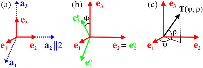
In order to find the spatial distribution of the cones of down-converted photons, we calculated numerically the non-collinear type-II PDC process in BiBO. We are interested in the degenerated case in which the down-converted photons share the same wavelength. The most basic reference system that we use is the crystal physical Cartesian system . It is linked to the crystallographic system (see Ref. [23]) by 2-fold axis, , see Fig. 1(a). The point group symmetry 2 of the monoclinic BiBO crystal structure allows the occurrence of enantiomorphic (i.e., ”left-handed” and ”right-handed”) species. All our samples for optical investigations were prepared using crystals that were grown as descendants from the same parent crystal and therefore posses the same handedness. For our crystals, the positive direction of (and ) corresponds to a positive sign of the pyroelectric coefficient (at constant stress) and to a negative sign of the longitudinal piezoelectric coefficient [24, 25].
In BiBO, the principal axes of the optical indicatrix coincide with the system only for while and change their orientation with wavelength. This orientational dispersion is illustrated by the angle in Fig. 1(b). For the fundamental and the down-converted wavelengths used in this work ( nm and nm), equals and , respectively [19].
Our calculations of the collinear and non-collinear PDC phase-matching cases [26], basically follows the calculation strategy described by Ref. [27]. For a chosen direction T of the fundamental wave vector , we define the propagation direction in spherical coordinates () with respect to (see Fig. 1(c)). The phase-matching conditions are satisfied when
| (1) |
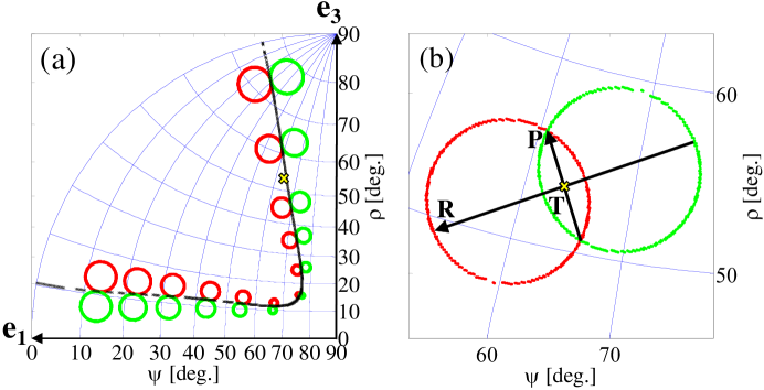
where is the phase-mismatch vector, and and are the wave vectors of the down-converted waves. First, we find the collinear phase-matching angles, as in this case Eq. 1 becomes scalar and simple to solve. Then, we use a search algorithm around the collinear direction to find the non-collinear directions that correspond to the minimal values of . We have chosen a numerical threshold value of . Photons are emitted into two cones with different, and not necessary perpendicular, polarizations. The stereographic projections of several down-converted emission cones onto the () plane are presented in Fig. 2(a). This projection preserves angles and projects circles in three dimensions as circles on the plane [26]. Each two tangent circles represent a non-collinear solution, where the direction of the fundamental wave is their collinear intersection point. The down-converted photons experience refraction when they emerge from the crystal to air, which depends on their propagation direction and their polarization. The calculation results given in this work are of the photon’s properties outside the crystal. For our wavelength parameters, the phase-matching calculations resulted in a suitable direction T with spherical coordinates and . In this case, the two down-converted cones intersect at an angle of and the intersection points are separated by . In order to simplify the crystal alignment process, it is convenient to define a sample reference system according to the PDC emission results. The direction of the wave vector of the fundamental wave is parallel to T. T is also normal to the input facet of the sample. We define P to be the vector connecting the two cones intersection points (see Fig. 2(b)) and R the vector that connects the most distant points on each circle. Consequently, T, P, and R form an orthogonal set. The BiBO samples used in our PDC experiments have spherical coordinates of , , and . The errors result from the finite grid resolution of the calculation for the intersection points.
2.3 The photons’ polarization
For any light propagation direction inside a non-cubic crystal, there are two orthogonal modes of the dielectric displacement field and , each with a different corresponding refractive index. In uniaxial crystals, such as BBO, these two modes are known as the ordinary (o) and extraordinary (e) polarizations, while in biaxial crystals they are known as the fast (f) and slow (s) polarizations, both behaving in general as an extraordinary wave [28].
When choosing the crystal parameters, we need to consider the polarization of the pump beam and the down-converted photons. It is possible to calculate the directions of the dielectric displacement vectors and of the two linearly polarized waves in respect to the physical axes . However, it is more convenient to define the photon polarizations with respect to the P and R directions. In the BBO crystal, the pump beam is polarized along the R direction, one cone is polarized in the same direction, and the other cone is polarized in the P direction. In BiBO, the pump beam should be polarized in its fast polarization mode in order to achieve maximal conversion efficiency, which usually differs from these convenient directions. For the general case, we define the cartesian coordinates of the propagation direction T by the unit vector in the optical indicatrix system . Using the Sellmeier formula for BiBO [19], we calculated the wavelength dependant principal refractive indices . From them we derived the slow and fast refractive indices [27]. Using these refractive indices, the ratios between the components of the normal polarization modes (i.e., the components of the unit vectors along the displacement field vectors ) are given by [28]
| (2) |
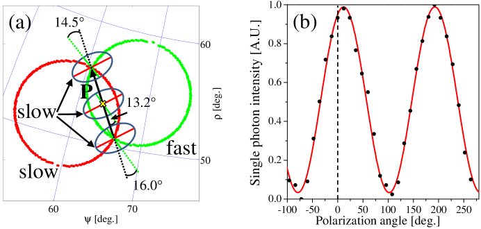
where i stands for ’fast’ or ’slow’. For our crystal parameters, the fast polarization mode of the pump beam was calculated to be from P, as shown in Fig. 3(a). We also measured this value by rotating the pump polarization direction with a half-wave plate. At each rotation step we took a picture of the down-converted circles. In Fig. 3(b) we plot the normalized intensity of the down-converted photons vs the polarization angle. Setting parallel to P, the maximal value was obtained at an angle of from P, within the crystal fabrication errors.
In order to calculate the polarization of the down-converted photons at the cones intersection points, we need to consider these two propagation direction inside the crystal. For the down-converted photons propagating at the top left (bottom right) intersection point in Fig. 3(a), the polarization direction of the fast wave is at ) from P. The slow polarization modes are perpendicular to the fast modes.
2.4 The effective second order nonlinearity
The effective strength of the second order nonlinear coefficient is an important consideration for the crystal design. For the uniaxial BBO crystal, there is an analytical expression that appears in Ref. [29]. Using the BBO d matrix elements from Ref. [5] and our wavelength parameters, a maximal value of pm/V is calculated. The calculation assumes a collinear type-II phase-matching process.
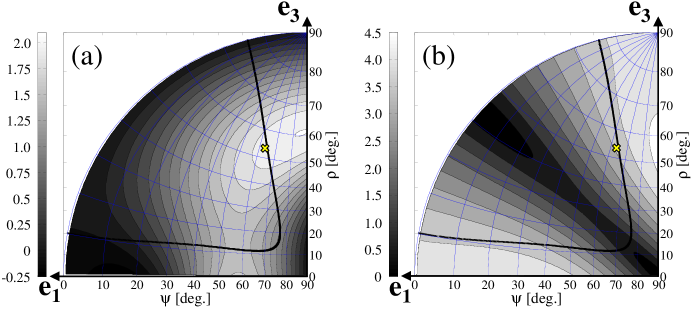
A rigorous treatment of biaxial crystals appears in Ref. [30]. We used the relevant formula for of collinear type-II phase-matching in the reference system (the indices refer to the pump and the down-converted photon polarization modes). The calculation results were rotated to the reference system, where for the parameters used in this work we get pm/V. The calculation considers a wavelength of 780 nm, although there is almost no wavelength dependency. For this calculation we used the four d matrix elements given in Ref. [30]. The results for any T direction are shown in Fig. 4(a). Note that because the calculation assumes collinear propagation, the results have significant meaning mainly in the vicinity of the collinear phase-matching curve. Furthermore, we have also removed the Kleinman symmetry assumption of Ref. [30] and derived a formula containing the eight d matrix elements given in Ref. [31]. This generalization resulted with a similar value ( pm/V). The almost doubled value of the nonlinear parameter of BiBO compared to BBO promises a major advantage for the generation of entangled photons.
2.5 The spatial walk-off angle
During the propagation through a birefringent crystal, the Poynting vector may point away from the direction defined by the k vector, depending on the beam polarization [32]. This phenomenon is called spatial walk-off. It should be taken into consideration when designing a polarization entangled photon source since it can create spatial labeling of the down-converted photons, which in turn will reduce the entanglement quality. The spatial walk-off angle between the Poynting vector and the k vector, together with the crystal thickness L, determines the overall spatial walk-off. The pump beam spot-size at the crystal should be large compared to the spatial walk-off in order to prevent the labeling effect [3].
In uniaxial crystals, such as BBO, an ordinary photon’s k vector and Poynting vector have the same direction while an extraordinary polarized photon deviates from that direction by an angle that can be calculated using a simple analytical expression [33]. In biaxial crystals, such as BiBO, both the fast and slow polarized photons deviate from the direction defined by the k vector while passing through the crystal. The spatial walk-off angle in this case is the angle between the two down-converted photons’ Poynting vectors.
We present here the results of a numerical approach for the walk-off calculation for BiBO. The direction of the Poynting vectors of the slow and fast down-converted photons are normal to the surface of the corresponding indicatrix. For each photon, we calculated three wave vectors with small deviations from their propagation direction k. We then found the plane that contains these three vectors. The direction normal to this plane is the direction of the Poynting vector. The angle between the two Poynting vectors of the slow and fast photons is the required walk-off angle. Note that it is also possible to treat this problem analytically, but as our numerical results are sufficiently accurate, we leave the rigorous treatment for a later work.
We calculated numerically the spatial walk-off angle in BBO and BiBO for a wavelength of nm. We have validated our numerical approach by comparing its results to the analytical expression for BBO [33]. The typical deviation between the numerical and analytical calculations is about degree. For collinear PDC in BBO the walk-off angle is , corresponding to an overall walk-off of m for a 2 mm thick crystal. The results for BiBO are presented in Fig. 4(b). For our crystal parameters, the calculated walk-off values are for one of the cones’ intersection points and for the other. These results correspond to a deviation of about m for the 1.5 mm thick crystal used in our experiments.
2.6 The temporal walk-off
As their name suggests, the two polarization modes propagate through the birefringent crystal with different group velocities. This may cause temporal distinguishability between the slow and fast photons. This phenomena is known as temporal walk-off. A birefringent crystal of thickness L separates the photons by
| (3) |
where is the speed of light in vacuum, and ) and ) are the group velocity and the ray refractive index of the slow (fast) photon, respectively. The ray refractive index and the refractive index are related via , where is the angle between the k vector and the corresponding Poynting vector[32]. The problem is more significant when is comparable to or larger than the coherence time . We addressed this issue with two methods. The first is to add two compensating crystals, cut at the same directions as the generating crystal but of half the thickness, in each down-conversion path [3]. The second approach is to overlap the two photons at a polarizing beam splitter (PBS) [34], as will be described later in Sec. 3.1.
For our crystal parameters, is approximately 0.05 for BBO and 0.15 for BiBO, which results with fs for a 2 mm thick BBO and fs for a 1.5 mm thick BiBO. Compensation is required in both cases as these values are larger than fs, the coherence time that corresponds to the used 3 nm filters.
2.7 Pump bandwidth and the entanglement quality
One advantage of down-converting a pulsed source over a continuous source is its energy concentration in a short coherence length which increases the probability of higher order PDC events. Furthermore, its timing information is inherited by the down-converted photons. However, the pulses broadband spectrum can cause a variety of undesired effects that decrease the entanglement quality.
| BBO | BiBO | |
|---|---|---|
| slow | ||
| fast |
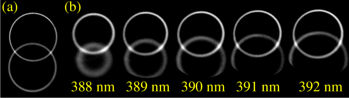
Figure 5(a) presents a picture of the down-converted photons from BBO recorded by a sensitive CCD camera through a 3 nm bandpass filter. The pump wavelength is nm with a full width at half-maximum (FWHM) of nm. Figure 5(b) shows pictures of the down-converted photons from BiBO for a few pump wavelengths. From these pictures we note a clear difference between the widths of the two BiBO circles, which is much smaller for BBO. For BiBO, the lower circle, which is made out of the slow polarized photons, changes much more than the fast polarized circle. This is due to the difference in the dispersion of the refractive indices at a wavelength of 780 nm for slow and fast polarized photons in this propagation direction. The calculated dispersion values from the Sellmeier formulas for BBO and BiBO are presented in Table 1. In the BiBO case there is a difference, while in BBO the dispersions differs only by about . To ascertain these results we calculated the processes that correspond to down-conversion of wavelengths at the FWHM values of the pump 2 nm spectrum
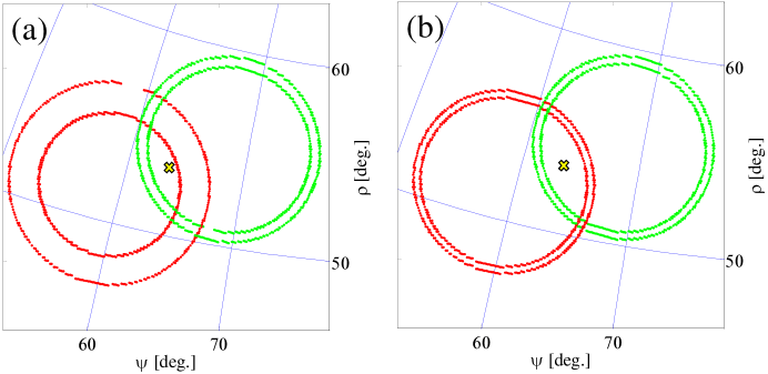
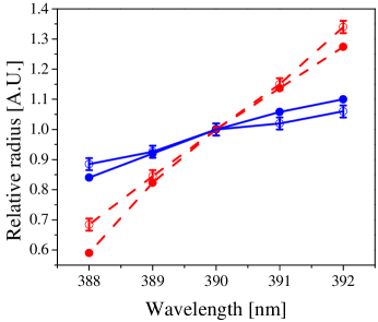
We present on a stereographic projection only the circles of nm (Fig. 6(a)). The circles angular radii are measured and normalized by the radius of 780 nm circles from down-converting 390 nm photons. Figure 7 presents a comparison between the numerically calculated radii and those measured from Fig. 5(b). The calculated (measured) slopes for the two polarizations differ by a factor of (). The calculated slow polarization circle is thicker than the fast polarization circle by times.
In order to separate the effect of the pump bandwidth from the effect of the filter bandwidth, we have also calculated the circle widths due to the filter bandwidth for a 390 nm pump. We consider the processes that result with photons at the FWHM of the 3 nm filters
The results are presented in Fig. 6(b). There is no significant effect due to the filter’s width. Thus, the slow polarized circle larger width is attributed to its higher dispersion, that results with the asymmetry shown in Fig. 5(b). The filters bandwidth do not add asymmetry between the circles. This conclusion suggests that a symmetric PDC picture may be obtained from BiBO using a continuous pump source.
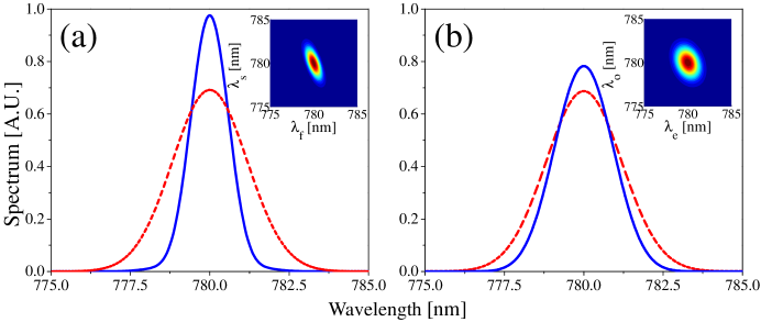
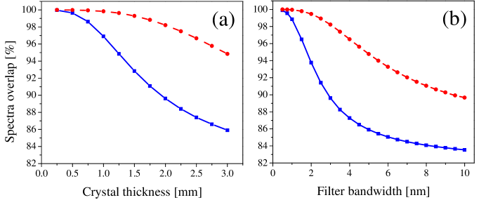
In order to evaluate the effect of these results on the quality of the generated entangled state, we calculated the spectra of the down-converted photons form a pulsed source in BiBO and in BBO. Our calculation was based on the work of Grice et al., that was previously applied to BBO [35]. As before, we used the collinear approximation. The normalized overlap between the two down-converted photons’ spectra corresponds to the quantum state visibility. The pump bandwidth and the crystal thickness also influence the down-converted spectra and thus, should be considered when designing such a polarization entangled photon source. Bandpass filters with the proper bandwidth can enhance the overlap between the two down-converted photons, and thus reduce the distinguishability between them. Figure 8 presents calculations of the down-converted spectra for a 2 mm thick BiBO and BBO crystals, assuming spectra with a FWHM of 2 nm for the pump photons and with 3 nm for the bandpass filters. The overlap between the integrated spectra of the two photons for BiBO and BBO are and , respectively. For the entanglement measurements, we used a 1.5 mm thick BiBO crystal, with a calculated spectral overlap of . Figure 9(a) presents the dependency of the BiBO and BBO spectra overlap on the crystal thickness for a 3 nm filter. The same spectra overlap as a function of the filter bandwidth for a 2 mm thick crystal is presented in Fig. 9(b). Although it seems as BBO can perform better than BiBO, spectral distinguishability can be eliminated [34].
3 Entanglement measurements
3.1 The experimental setup
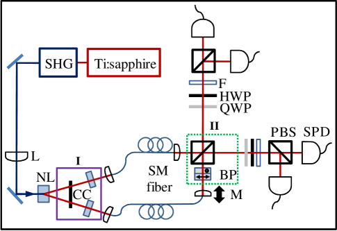
The setup used in this experiment is presented in Fig. 10. The radiation of a mode-locked Ti:sapphire laser at 780 nm is up-converted to 390 nm by second-harmonic generation (SHG). The beam is focused by a lens (L) on the BBO or BiBO crystal (NL). The spatial modes of the pump beam and the down-converted photons are matched to optimize the collection efficiency [36]. The photons are coupled into single mode fibers (SM), where their polarization is adjusted by polarization controllers. The relative propagation delay between the two optical paths is adjusted by translating one of the fiber ends with a linear motor (M). A quarter-wave plate (QWP) and a half-wave plate at each path are used for the quantum state tomography. The photons are spectrally filtered by using 3 nm wide bandpass filters (F) and coupled into multimode fibers that guide them to the single-photon detectors (SPD).
We tried two configurations in order to remove the temporal and spectral distinguishability of the down-converted photons. The elements used in each configuration are labeled I and II in Fig. 10. In the first configuration (I), the photon polarizations are rotated by a half-wave plate (HWP), and temporal and spatial walk-offs are corrected by compensating crystals (CC) of half the thickness of the generating crystal. In the second configuration (II), two perpendicularly oriented Calcite crystals (arrows indicate the optical axis direction) are used for aligning the birefringent phase (BP). The photons are then overlapped at a PBS.
3.2 Experimental results
We generated polarization entangled states with a 1.5 mm thick BiBO crystal and compensated for distinguishability effects with two configurations [3, 34] (see Sec. 3.1). In order to characterize the entanglement quality, we recorded visibilities [3] at three polarization bases (horizontal and vertical linear polarizations (HV), plus and minus linear polarizations (PM), and right and left circular polarizations (RL)). Full quantum state tomography was also performed. Comparison is made with results obtained using a 2 mm thick BBO crystal, in a setup optimized for its parameters.
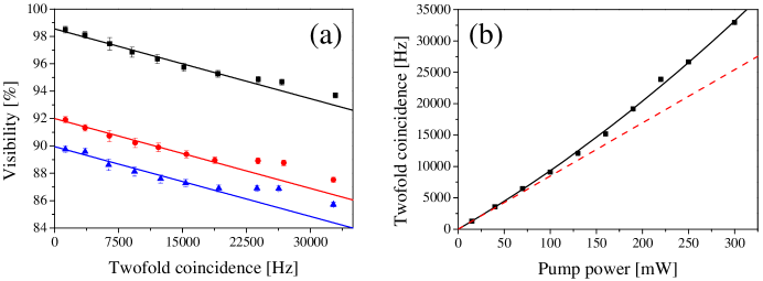
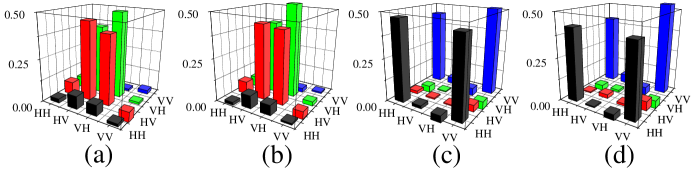
Using configuration I, we generated the Bell state. The recorded visibilities were , , and , with typical twofold coincidence rates of 34000 Hz (pump power of 300 mW). The detection efficiency, i.e., the ratio of the rates of coincidence events and of single events, was . By lowering the pump power with a variable neutral density filter these values were improved (see Fig. 11(a)). The visibilities dependence on the pump power is due to higher order PDC events that result from the improved generation efficiency. The extrapolated visibilities at zero pump power are , and . Another manifestation of the high generation efficiency is the stimulation process that can be seen from the dependence of the twofold coincidence rate on the pump power (see Fig. 11(b)). A quadratic function fits the data well, and clearly deviates from the linear slope at low pump powers, a clear signature of stimulated PDC. Density matrices were measured both at low power (P=40 mW, Fig. 13(a)) and high power (P=300 mW, Fig. 13(b)) [37]. Their fidelities are and , respectively, calculated using a maximal likelihood algorithm [38].
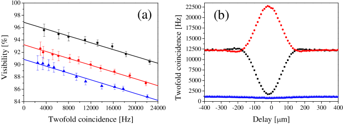
The second compensation scheme we have used (configuration II), was first suggested and experimentally demonstrated by Kim et al. [34]. Using this configuration, we generated the Bell state. The recorded visibilities were , and , with typical twofold coincidence rates of 22500 Hz (pump power of 310 mW, see Fig. 12(a)). The lower count rates can be attributed to the lack of spatial walk-off compensation due to the missing compensating crystals. The detection efficiency was . The extrapolated visibilities at zero pump power are , and . The density matrices for pump powers of 42 mW and 310 mW are shown in Figs. 13(c) and 13(d), respectively. Their corresponding calculated fidelities are and .
There is another way to evaluate the entanglement quality when the second configuration is used. Scanning the path difference before the PBS and recording coincidences at the rotated base, simultaneously projects on the and states (see Fig. 12(b), pump power is 320 mW). The dip visibility is , similar to the high pump power visibility at the PM basis. This value is affected by contributions from high order events. The contribution of the second order term to the visibility can be estimated from the coincidence rate of two orthogonally polarized photons at the same PBS output port. After subtracting the second order events contribution, the visibility becomes , which is comparable to the PM visibility at low pump power.
For comparison, we have generated polarization entangled photons in the Bell state from a 2 mm thick BBO crystal with configuration I. The measured visibilities in the three polarization bases , and were , , and , respectively. The typical twofold coincidence rate was 37500 Hz for a pump power of 410 mW and detection efficiency of . We have also measured the density matrix and calculated the state fidelity to be .
A meaningful comparison between BiBO and BBO should take into account the differences between the two crystals we checked. The two crystals were also measured in different setups, but these were individually optimized to optimize the collection efficiency, which depends on the crystal parameters. The BBO crystal we used was 2 mm thick and anti-reflection coated, while the BiBO was only 1.5 mm thick and uncoated. The thickness difference accounts for a factor of 1.78, as the PDC efficiency depends quadratically on the crystal thickness [2]. The lack of coating for BiBO also accounts for a loss, assuming the pump beam and the down-converted photons hit the crystal facets perpendicularly. It should also be considered that, due to some technical issues, we pumped the two crystals with different powers. Thus, we calculate the down-conversion efficiency as the number of detected pairs per second, per mW of pump power, per mm2 of crystal thickness. The efficiency values for BiBO and BBO, as measured in configuration I, are Hz mW-1mm-2 and Hz mW-1mm-2, respectively. These values account for an improvement by , compared to the 3.09 ratio predicted by the calculated values of BiBO and BBO (see Sec. 2.4).
4 Conclusions
We have studied the various properties of the biaxial BiBO crystal, which are relevant for utilizing it as a polarization entangled photon source using non-collinear type-II PDC and a pulsed pump source. Theoretical and numerical treatment of the relevant crystal parameters is presented. We calculated the crystal cutting angles, the polarization directions, temporal and spatial walk-offs, and the effective nonlinear coefficient. We have also demonstrated the effects of crystal dispersion and the broad spectrum of the pulsed pump on the angular and spectral properties of the down-converted photons, and therefore on the entanglement quality. The experimental results demonstrate the higher efficiency of BiBO compared to the commonly used BBO, and the potential BiBO has as an ultra bright source of entangled photons. Although it focuses on BiBO, our work can be considered as general guidelines for considering any other biaxial nonlinear crystal as a non-collinear type-II polarization entangled photon source. As there are a growing number of quantum optics experiments that require highly efficient PDC sources, we hope that this work will encourage the use of BiBO as a source for polarization entangled photons.
Acknowledgments
The authors thank the Israeli Science Foundation for supporting this work under Grants No. 366/06 and No. 546/10.