A New Type of Traveling Interface Modulations in a Catalytic Surface Reaction
Abstract
A new type of traveling interface modulations has been observed in the NH3 + O2 reaction on a Rh(110) surface. A model is set up which reproduces the effect, which is attributed to diffusional mixing of two spatially separated adsorbates causing an excitability which is strictly localized to the vicinity of the interface of the adsorbate domains.
pacs:
82.40.NP, 68.43.Jk, 68.37.Xy, 82.65.+rPattern formation in reaction-diffusion systems covers a wide range of fascinating phenomena in liquid phase chemistry, biochemistry, biology and catalytic surfaces (Cross and Hohenberg, 1993; Kapral and Showalter, 1995; Imbihl and Ertl, 1995). In general, the patterns arise due to the coupling of a non-linear reaction term with diffusion. Reaction fronts, target patterns and spiral waves, stationary concentration patterns and chemical turbulence have been seen. Various additional factors like global coupling, diffusional anisotropy, energetic interactions and cross diffusion of reactants may add to the complexity and diversity of the chemical wave patterns.
Extended bistable systems generically exhibit fronts (also called interfaces or domain walls) connecting one phase in one part of the spatial domain to the other phase in some other part of the domain. In two spatial dimensions the most natural geometry is a straight line for the front position, suitably defined as some intermediate level curve of the solution. However, already in simple bistable systems, initially straight interfaces between two domains may undergo a number of instabilities, see, e.g., (Pismen, 2006, Chapter 2) for an overview. A typical case is a linear transverse instability leading to a regular (periodic) or irregular bending of the front, but with small amplitude, which may then often be described by Kuramoto-Sivashinksky type of equations, see Kuramoto (1984). Another possibility is that an instability does not saturate at some small amplitude, which may yield “fingering” and labyrinthine patterns Lee et al. (1993); Goldstein et al. (1996); Hagberg et al. (2006). Similar wave instabilities also occur in excitable media, see, e.g., Zykov et al. (1998).
Here we report on a new type of instability and self-organization of an interface, namely interface modulations that originate from corners and travel along the interface in a pulse like fashion, leaving the interface position almost unperturbed behind. These excitations have been observed in the NH3 + O2 reaction on a Rh(110) surface. The effect is attributed to diffusional mixing of two spatially separated adsorbates causing an excitability which is strictly localized to the vicinity of the interface of the adsorbate domains. Combining a bistable with an excitable system, we set up a general model which reproduces the traveling interface modulations seen in the experiment.
The reaction we study is the catalytic ammonia oxidation with O2 on a Rh(110) surface under low pressure conditions ( mbar) in a UHV chamber equipped with a photoemission electron microscope (PEEM) as spatially resolving method. Illuminated with a D2 discharge lamp (5.5–6 eV) photoelectrons are ejected which allow an imaging of the local work function with a spatial resolution of m and the temporal resolution of video images (20 ms). At elevated temperatures (T400 K) both reactants dissociate upon adsorption into their atomic constituents Oad, Nad, and Had Comelli et al. (1998); Kiskinova et al. (1995). The atomic adsorbates recombine, forming N2, NO, and H2O as main products. Also, H2 is produced and desorbs at a high rate, and hence the coverage is always small. The adsorbates N and O form a large number of ordered reconstruction phases on Rh(110) but under our reaction conditions only the (21)-N/(31)-N corresponding to and the c(26)-O corresponding to are relevant Gierer et al. (1995). In addition, a mixed coadsorbate phase c(24)-2O,N may form.
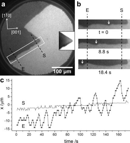
Over a broad range of parameters the reaction exhibits simple bistability, i.e. one observes a broad hysteresis in the reaction rates in heating/cooling cycles. The reactive branch is associated with the (21)/(31) of nitrogen, the unreactive branch with the c(26) of oxygen. Transitions between the two states occur via fronts. If one adjusts conditions close to equistability both phases are simultaneously present as shown by the PEEM image in Fig.1a. Since oxygen adsorption strongly increases the work function (WF) (eV) high Oad coverages are imaged dark whereas adsorbed nitrogen which only causes a maximum WF increase of 280 meV appears bright Makeev et al. (2001).
The position of the interface is nearly stationary but one notices small lateral displacements of the interface which emanate near the sharp corner in the phase boundary and then propagate in a pulse-like manner along the interface. This process is depicted in more detail by the frames in Fig.1b displaying an enlarged section of the PEEM image in (a). The velocity of the pulse-like excitations is about 6 m/s. Cross sections of the interface showing the temporal variation of the interface positions at two different points, E and S, are displayed in Fig.1c. Near the sharp corner, in point S, the amplitude is below the detection limit. Further away, at point E, the amplitude is substantial varying between a few m and 20 m. One notes a drift of the average interface position of about 15 m over an observation time of 170 s which is due the fact that the equistability conditions are not exactly met. The time series exhibits irregular behavior but the excitability of the interface is quite stable and can be observed over several hours. The average period of the local excitations is around 10 s. In our experiments we found no correlation between the interface angles and interface excitations, and the crystallographic directions of the surface.
In order to understand why the excitations remain localized at the interface and do not extend into the interior of the phase it is helpful to look into the chemically rather similar system Rh(110)/NO + H2 which can be considered as well understood Mertens and Imbihl (1994); Makeev et al. (2001). Some spectacular chemical wave patterns including rectangularly shaped target patterns and spiral waves and traveling wave fragments were found there. The excitable behavior in this system was shown to be based on a cyclic change of three different structures; the c(26)-O of oxygen, the (21)/(31)-N of nitrogen and the c(24)-2O,N as mixed coadsorbate phase. In the NH3 + O2 reaction only two of these three structures are present as stable phases while the mixed coadsorbate phase is missing. Apparently the mixed phase does not form by coadsorption.
If we assume that by surface diffusion this mixed phase may form, its formation is restricted to a boundary layer along the interface where the two separated adsorbates, N and O, can penetrate each other by diffusion. Excitability would then be strictly restricted to a boundary region along the interface and this is what we basically see in the experiment. Using the diffusion values which have been used for quantitative simulation of the chemical wave patterns in Rh(110)/NO+H2 we can estimate the diffusion length l at T=740 K for =10 s with resulting in m for N and 13m for O Makeev et al. (2001). The inset in Fig. 1a shows a dark boundary region of a few m width which is consistent with the high WF of 1.1 eV of the c(24)-2O,N phase Mertens et al. (1997).
For modeling the observed behavior we set up a dimensionless 3-variable model for bistable/excitable media which in 2D reads
| (1a) | ||||
| (1b) | ||||
| (1c) | ||||
with diffusion constants, , parameters , and . In short, using with obvious notations we write
| (2) |
The system (1) is composed of an excitable –subsystem (FHN like) and a bistable –subsystem (Allen-Kahn or Nagumo equation), which has front solutions.
The basic idea is that (i) through the interaction with the -variable the -subsystem is excitable only in the vicinity of the front position (where ), and that (ii) these localized excitations of the –subsystem then push or pull the -front. Since on surfaces the diffusion of the different species is not independent of each other, we include cross-diffusional terms which have to be symmetric according to Onsager’s reciprocity relation. On surfaces cross diffusion arises (i) due to the vacant site requirement for diffusional hops and (ii) due to energetic interactions between coadsorbed species Evans et al. (2002); Vanag and Epstein (2009). In particular, the strong repulsive interaction between coadsorbed oxygen and nitrogen shows up in a downward shift in the desorption maximum by about 100 K Comelli et al. (1992). As will be shown below cross-diffusion becomes important for the nucleation of excitation pulses.
Thus, we choose parameters in such a way that in the absence of , i.e., for , the ODE subsystem is excitable. Its unique ODE fixed-point is given by , . This fixed point is asymptotically stable and globally attracting, but for small rather small perturbations may lead to large excursions.
For , or equivalently , (1c) is a standard bistable equation
| (3) |
i.e., the kinetics has the two stable fixed points and the unstable fixed point . It is well known, that (1c) has travelling front solutions, e.g., , as , in fact explicitly given by For () fronts travel left (right), meaning that the phase invades the phase (resp. vice versa).
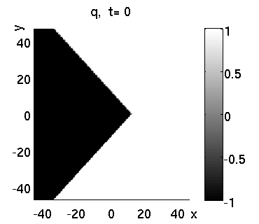
Since the Laplacian is isotropic any orientation of fronts is allowed. As a consequence, (3) also has (smooth) V–shaped fronts , propagating with speed , see Fig. 2 and Ninomiya and Taniguchi (2005).

Now considering the coupling between (1a,1b) and (1c) in more detail we note that becomes large near corners of the front, and vanishes away from the front; thus excitations originate near corners. On the other hand, the term in (1a) makes the kinetics less excitable away from the front, and thus excitations in the PDE (1) stay near the front. Finally, the term in (1c) has the effect that the excitations push or pull the –front, as seen in the experiment.
System (1) was integrated numerically in a domain for various parameters using different initial conditions (IC) and boundary conditions (BC). For the IC we are led by the experiment to consider “wedges” in , e.g.
| (6) |
where are the slopes of the sides and represents the position of the tip. For we choose the fixed point . Given an IC of the form (6), it is natural to integrate (2) in a moving frame with to keep the tip of the wedge away from boundaries, i.e., to integrate
| (7) |
For the BC the problem then is that while planar fronts can be easily simulated with Neumann BC, for V–shaped fronts influences of boundaries on the fronts are difficult to avoid. Here we choose Dirichlet BC for (7), namely
| (8) | |||||
The latter fixes the front shape and position at the top and bottom boundary.
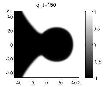
For the IC and BC chosen above, we obtain the simulation results displayed in Fig. 3. Excitations nucleate at the tip of the wedge and then travel along the front, pushing it back and forth. The chosen means that () pushes down (up), such that here the excitations push back the frontline.

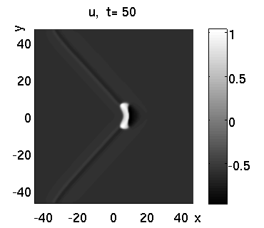
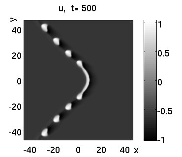
The firing process at the tip repeats for some time (essentially depending on the size of the computational domain), and the process is accompanied by some overall reshaping of the wedge. Aside from boundary effects, this reshaping is determined by the following factors. The -front does not fully recover its former position after a pulse has passed. The tip of the wedge, where pulses nucleate, drifts to the right. To counteract this effect we chose (instead of which without coupling to the system would give a stationary tip position). As a consequence of decreasing , the unperturbed sides of the wedge drift to the left. The overall balance gives an almost stationary average front position up to . For excitations that have emanated from the tip are reflected by the boundary.
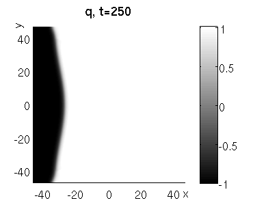
The behaviour in Fig. 3 is quite robust with respect to most parameters and IC’s, including the opening angle of the wedge. A decisive parameter for the evolution is . For the excitations push the front too strongly thus destroying the wedge by creating a bubble. For the excitations pull the front too strongly thus flattening the wedge, see Fig. 4.
a) b)
In summary, we observed excitability in a catalytic surface reaction which remained strictly localized at the interface of two domains of different adsorbates. The excitations were traveling along the interface in a pulse–like way, causing lateral displacements of the interface position. Mechanistically, the localized excitability can be traced back to the diffusive mixing of the two separate adsorbates at the interface causing the formation of a mixed coadsorbate phase which is required to make the system excitable. The experimentally observed behavior could be reproduced with a general dimensionless 3-variable model which couples the excitability of a subsystem to the position of a frontline. The nucleation of excitations at corners of the front was explained with cross-diffusional effects which are very sensitive to the local front geometry. Similar dynamical behavior should be expected in all systems which (i) are essentially bistable in the sense that there are two asymptotically stable phases, but where (ii) diffusive mixing at the interface can locally change the dynamical behavior from bistable to excitable.
References
- Cross and Hohenberg (1993) M. Cross and P. Hohenberg, Rev. Mod. Phys. 65, 854 (1993).
- Kapral and Showalter (1995) R. Kapral and K. Showalter, eds., Chemical Waves and Patterns (Kluwer, Dordrecht, 1995).
- Imbihl and Ertl (1995) R. Imbihl and G. Ertl, Chem. Rev. 95, 697 (1995); R. Imbihl, in Handbook of surface science, 341 (Elsevier, Amsterdam, 2008).
- Pismen (2006) L. Pismen, Patterns and Interfaces in Dissipative Dynamics (Springer, Berlin, 2006).
- Kuramoto (1984) Y. Kuramoto, Chemical oscillations, waves, and turbulence (Springer, Berlin, 1984).
- Lee et al. (1993) K. Lee, W. McCormick, H. Ouyang, and H. Swinney, Science 261, 192 (1993).
- Goldstein et al. (1996) R. Goldstein, D. Muraki, and D. Petrich, Phys. Rev. E 53, 3933 (1996).
- Hagberg et al. (2006) A. Hagberg, A. Yochelis, H. Yizhaq, C. Elphick, L. Pismen, and E. Meron, Physica D 217, 186 (2006).
- Zykov et al. (1998) V. Zykov, A. Mikhailov, and S. Müller, PRL 81, 2811 (1998).
- Comelli et al. (1998) G. Comelli, V. R. Dhanak, M. Kiskinova, K. C. Prince, and R. Rosei, Surf. Sci. Rep. 32, 165 (1998).
- Kiskinova et al. (1995) M. Kiskinova, A. Baraldi, R. Rosei, V. R. Dhanak, G. Thornton, F. Leibsle, and M. Bowker, Phys. Rev. B 52, 1532 (1995).
- Gierer et al. (1995) M. Gierer, F. Mertens, H. Over, G. Ertl, and R. Imbihl, Surf. Sci. 339, L903 (1995).
- Makeev et al. (2001) A. Makeev, M. Hinz, and R. Imbihl, J. Chem. Phys. 114, 9083 (2001).
- Mertens and Imbihl (1994) F. Mertens and R. Imbihl, Nature 370, 124 (1994).
- Mertens et al. (1997) F. Mertens, S. Schwegmann, and R. Imbihl, J. Chem. Phys. 106, 4319 (1997).
- Evans et al. (2002) J. Evans, D.-J. Liu, and M. Tammaro, Chaos 12, 131 (2002).
- Vanag and Epstein (2009) V. V. Vanag and I. R. Epstein, Phys. Chem. Chem. Phys. 11, 897 (2009).
- Comelli et al. (1992) G. Comelli, S. Lizzit, P. Hofmann, G. Paolucci, M. Kiskinova, and R. Rosei, Surf. Sci. 277, 31 (1992).
- Ninomiya and Taniguchi (2005) H. Ninomiya and M. Taniguchi, J. Diff. Eq. 213, 204 (2005).