Low-threshold directional plasmon lasing assisted by spatially coherent surface plasmon polaritons
Abstract
We theoretically propose directional, low-threshold plasmon lasing in both the near-infrared and visible wavelengths by utilizing spatially coherent surface plasmon polaritons on a meta-surface. The gain strength required for threshold lasing can be tuned down to a large extent through compatible structural parameters. Our calculations show that no more than 65 cm-1 at 193.5 THz (1.55 m) or 267 cm-1at 474THz (0.633 m) of gain coefficient is sufficient to compensate for the dissipation of metal films for threshold lasing; these values are smaller than any reported studies at the same frequencies. These findings present a planar solid-state route for plasmon lasing that is highly efficient and spatially coherent.
pacs:
42.55.-f,42.25.-p,73.20.Mf,78.20.CiI Introduction
In recent years, nanophotonics has attracted considerable attention as one of the emerging fields of modern science and technology. Active devices, especially coherent sources with high efficiency, are of great importance for the development of nanophotonics. The amplification of the evanescent field and strong confinement of light in a subwavelength scale are crucial for active nanophotonic devices to achieve superior performance. Surface plasmon polaritons (SPPs) provide a feasible route for manipulating light beyond the diffraction limit. In 2003, Bergman and Stockman proposed surface plasmon amplification by stimulated emission of radiation (SPASER)1 ; 2 . A spaser—referring to the accumulation of a large number of SPPs in a single mode assisted by a gain medium—is precisely the plasmonic counterpart of the nano-laser. In principle, one of the most important applications of SPP amplification is plasmon lasing3 ; 4 . As energy dissipation in metals significantly reduces the lifetime of SPPs in the infrared and visible frequencies, the gain of the active medium must prevail over the dissipation of metals in order to sustain the survival of a spaser. Many efforts related to SPP amplification have been devoted to loss compensation in metal-dielectric structures5 ; 6 ; 7 ; 8 . The first experimental verification of the spaser used gold nano-particles encapsulated in dye-doped silica shells, which support a collective SPP mode with a high quality factor (Q-factor)9 .
Planar design is preferred for the realization of spasing as well as plasmon lasing for the sake of fabrication convenience and device integration. However, as a finite-sized planar structure is usually incapable of strong light confinement, a high-gain medium is required in order to compensate for the radiation and damping losses from the planar structure. One solution to this difficulty is to utilize “trapped mode” of a plasmonic meta-surface10 . A split ring resonator with weak asymmetry (ASR) possesses a leaky mode that is poorly coupled with free-space photons. A plasmonic metamaterial slab composed of an array of such ASRs will facilitate SPP amplification and lasing with low-gain material when the leaky mode is excited. Subsequent experimental investigation showed that the loss from the nano-sized metallic ASRs could be compensated for by the gain of quantum dots11 .
It is worth noting that a magnetic meta-surface can support spatially coherent SPPs which are of high Q-factor as well. The subtle concept, in contrast to the “trapped mode” which is derived from dark mode of a single resonator, comes from the SPPs in harmonic mode12 . These spatially coherent SPPs are actually the leaky waves of a slab waveguide which can not be determined by a single resonator. They must be in harmonic mode to sustain a leaky wave character, giving rise to a high Q-factor which can be of one or two orders larger as compared to that of the SPPs in fundamental mode. In this paper, we theoretically propose that such spatially coherent SPPs present a practical solution for low-threshold plasmon lasing in both the near-infrared and visible regimes. The gain coefficient of the active medium for threshold lasing can be tuned down by structural parameters to a large extent, even down to values much smaller than those of semiconductor quantum wells. Two model samples are presented with structural parameters that are feasible for practical fabrication. The threshold gain coefficient 65 cm-1 at 193.5 THz (1.55m) is much smaller than those of other lasing systems reported in the same infrared frequency region10 ; 13 ; 14 . The low threshold arises from the high Q-factor of the SPPs in harmonic mode and from the strong confinement of the local field in the active layer, both of which are not easy to establish in a planar solid-state system. The high directionality of the lasing beam with the full width at half maximum (FWHM) of in E-plane () and in H-plane () is verified by finite-difference-in-time-domain (FDTD) simulations, where and are the polar angle and azimuthal angle.
II Reflectance amplification assisted by spatially coherent SPPs
Our planar lasing system is schematically illustrated in the inset of Fig. 1(a). Lying on the plane, the slab comprises an upper layer of a metallic lamellar grating with a thickness of , a metallic ground plane, and an active layer with a thickness of sandwiched between them. The metallic strips with a width of are separated by a small air gap , giving rise to a period of for the lamellar grating. The geometric parameters of our model in the infrared region are m, m, m, m, and m.
The SPP resonances on the slab can be characterized by the amplification of reflection coefficients. The metals in our system are assumed to be silver with permittivity defined by a Drude model15 , where THz, THz. And the dielectric layer is assumed to be active with a complex permittivity , in which the imaginary part is positive. We perform a rigorous coupled-wave analysis16 ; 17 to calculate the coefficient of the order of the reflected Bloch wave components, in which and denote the incident angle and the frequency of plane wave incidence. The incident plane wave is transverse magnetic (TM) polarized with the magnetic field parallel to the direction and in-plane wave vector , where is the wave vector in a vacuum. The gain strength of the active layer is defined by a coefficient, . In the calculations, different values of gain strength are taken into account by varying the imaginary part of the complex permittivity while keeping the real part fixed at .
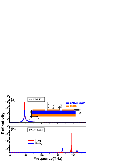
Figure 1 shows the calculated reflection spectra in the 0 order under an incident angle of and an imaginary part of the permittivity of the active layer of . When the gain strength is strong (), there exists an amplification peak fixed at 46.3 THz (m) that is almost independent of the incident angle. In contrast, when the gain strength is weak (), the amplification peak at 46.3 THz disappears, and a new peak emerges at 193.5 THz (m) under normal incidence. Under oblique incidence, the emerging peak splits into two peaks with varying frequencies that are sensitive to the incident angle; see, for example, the dotted line in Fig. 1(b) for the two peaks at 166.1 THz and 211.9 THz with . The angle-dependent amplification peaks are obviously different from the angle-independent peak in regards to the physics of their origin. Their time-reversed counterparts are the angle-dependent and angle-independent absorption peaks that we have investigated before12 . An angle-independent peak, requiring a sufficiently large gain/absorption coefficient of the dielectric layer, comes from the excitation of a localized SPP resonance in a fundamental mode that is dominated by the 0 order guided Bloch mode in the dielectric. The angle-dependent feature comes from the spatially coherent SPP resonance in a harmonic mode that is dictated primarily by the 1 orders of the guided Bloch mode in the dielectric.
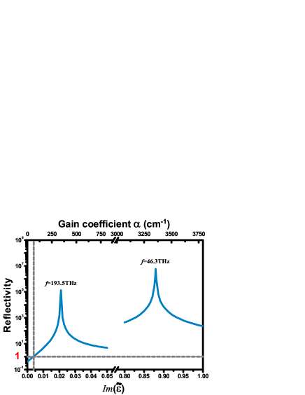
The reflection amplification of the two resonant peaks as a function of the gain strength in the active layer is plotted in Fig. 2. It should be noted that a rather low gain strength cm-1is sufficient to compensate for the loss of metals and to sustain the amplification of the guided waves in the active layer as well as the reflectance amplification at 193.5 THz. The amplified reflectance increases exponentially with the increase of , until a maximal amplification of about is reached at an optimal value of cm-1. In contrast, we see from Fig. 2 that the reflectance amplification at 46.3 THz requires much stronger gain strength, which is unattainable for most of the existing active media at this frequency.
Additional calculations indicate that the gain strength required for the reflection amplification at 193.5 THz can be reduced further, provided that a smaller air gap or a thinner dielectric layer which matches the gain strength is adopted. The property provides us with a good opportunity for finding a balance between ease of fabrication and attainable gain strength of the active layer. Usually thermal conductivity of active medium becomes larger with respect to higher temperature. A weaker gain strength required for threshold lasing also implies that we can find an appropriate structure for plasmon lasing that is robust against thermal noise, or intuitively that the thermal noise is somewhat “suppressed” by spatially coherent SPPs. This is advantageous for room-temperature plasmon lasing as one goal being pursued. At this stage, it is imperative for us to apply the spatially coherent SPP modes for low-threshold plasmon lasing as such a SPP mode with a long lifetime, which is compatible to the structural parameters, will create extensive adaptability in material selection and feasible way for practical implementation of plasmon lasing.
III Rate equation analysis: lasing threshold and dynamic processing
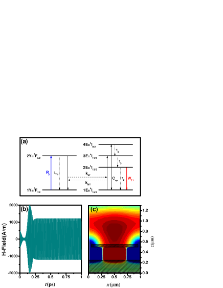
Now we investigate the threshold condition of our lasing system by using the realistic material parameters. A widely used gain medium, Ytterbium-erbium co-doped material Er:Yb:YCOB is adopted as the active medium for lasing around m18 ; 19 . Its level assignment is shown in Fig4 (a). The population density on every level evolves according to the dynamic rate equations20 , and can be solved for steady-state conditions:
| (1) | ||||
| (2) |
| (3) |
| (4) |
| (5) |
and are the population density and radiative lifetime of corresponding levels. are the branching ratio for transitions from the to levels. is the pump rate from 1Y to 2Y level. and are the forward and backward energy transfer coefficient corresponding to 2Y1E3E1Y and backwards. is the coefficient of the cooperative upconversion 2E2E4E1E. is the stimulated-emission coefficient. is the inverted population difference between 1E and 2E level. is the population density of the lasing mode. Considering the conservation of population density, we have and . The threshold lasing can be evaluated under steady-state condition as , where is the Q-factor of the lasing mode. We note that the threshold inversion density can be estimated by ; and a higher Q-factor as a result of lower radiation loss and damping loss of the lasing mode will give rise to lower threshold doping concentrations or pumping power dominated by .
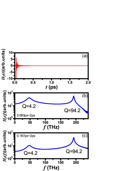
The Q-factor of SPP mode can be extracted from the FDTD numerical simulations by assuming that the dielectric is passive and lossless with a dielectric constant equal to 1.7, the real part of that of Er:Yb:YCOB. A one-way TM polarized plane wave with a Gaussian distribution in time domain is normally incident on the model slab. The incident plane is m away from the top surface of the model slab. A probing plane is positioned m behind the incident plane to monitor the reflected wave fields. Figure 3(a) illustrates the time-domain spectroscopy of the magnetic local field at the probing plane. The frequency spectra in Figs. 3(b) and 3(c) present the Fourier transformed data of the time-domain spectroscopy in different time spans ps and ps. A broad peak and a narrow one, centered at 45.0THz and 192.6THz respectively, are observed in both figures. More calculations in time domain indicate that the decay rate of the broad one is much quicker than that of the narrow one. These two peaks correspond to the localized SPP resonance in fundamental mode at 46.3THz and the spatially coherent SPP resonance in harmonic mode at 193.5THz, as shown in Figs. 1 and 2. Q-factor of a SPP resonance can be extracted from the FWHM in the frequency spectra. A low Q-factor of only 4.2 and a high Q-factor of 94.2 are derived at 45.0THz and 192.6THz in the frequency spectra. The Q-factor can also be estimated with the exponential decay rate of the mode in time domain, as , where is the lifetime of the mode. In our case, the life time of each mode is, ps and ps, respectively, reproducing exactly the same values of Q-factor at the two resonance frequencies as the former method. We note that the Q-factor of spatially coherent SPP mode is of one order larger than that of localized SPP mode. And a higher Q-factor will be advantageous in the field amplification in gain medium and the stimulated emission radiations. By applying the condition of threshold lasing at 192.6THz to the rate equations, a threshold doping concentration ions/m3 of Er3+ is obtained, which falls inside the typical concentration range of Er3+ ions in Er:Yb:YCOB. In our calculations, the Yb3+ concentration is assumed to be fixed at ions/m3. It is not likely to utilize a fundamental SPP mode of the meta-surface to realize plasmon lasing due to the low Q-factor of 4.2, as the required Er3+ concentration ions/m3 is hard to achieve in Er:Yb:YCOB. More calculations show that it is not very easy for the Q-factor of the local SPP resonance in fundamental mode to exceed a value of 10 by tuning structural parameters.
Now we perform FDTD simulations to dynamically demonstrate a lasing example of our model slab21 ; 22 . Periodic boundary is adopted in our simulations. the Yb3+ concentration and the Er3+ concentration are chosen at 5.01027 irons/m3 and 4.01025 irons/m3, respectively. Calculations are performed by assuming a pumping power at W which is beyond the threshold W . The magnetic field pattern of the cavity and its emission field distribution at a typical time (ps) are shown in Fig. 4(c). Fig. 4(b) shows the time dependence of the averaged over all the spatial points in plane covering the unit cell.
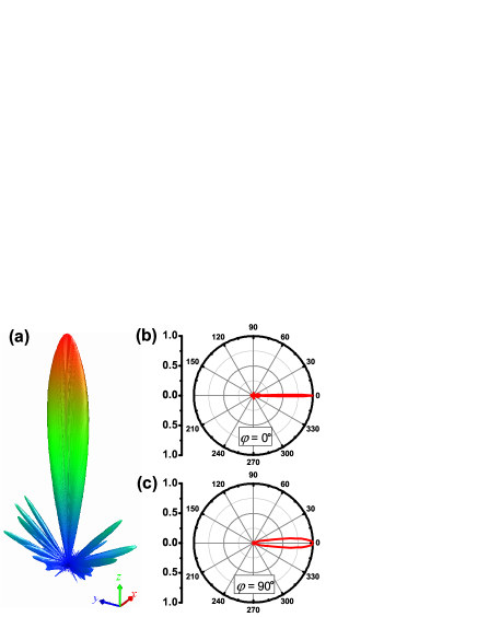
The lasing at 192.6THz of a real structure is also considered. In the FDTD simulations, the lateral size of the model slab is 20 periods along direction (the direction of the grating) , and the length of the stripe along direction is . The angular dependence of far-field patterns are calculated at the steady-state. We see from Fig. 5 that most of the energy of the lasing beam is confined in a small solid angle. The angle-dependent power is normalized to the maximum at the normal direction. The FWHM in the E-plane () is , and that in the H-plane () is . The highly directional lasing beam shall be attributed to the excitation of a spatially coherent SPP mode on the slab, as such an SPP mode will inherently establish phase correlations among the unit cells on the meta-surface due to the dominant 1 orders of guided Bloch modes in the active layer.
IV Lasing in the visible region
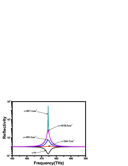
Our lasing system can also operate at visible wavelength with an appropriate design. Figure 6 presents an example of reflectance amplification at 474 THz (nm). A rather low gain coefficient of cm-1 is enough for the compensation of metal dissipation. Even the optimal gain coefficient, cm-1 for the maximum reflectance, falls in the range of the gain coefficients of the most commonly used active media in this frequency regime, such as organic dye molecules, semiconductor quantum wells, and nano-crystal quantum dots. The structural parameters are as follows: grating period nm, metallic strip width nm, air gap width nm, grating thickness nm, and dielectric layer thickness nm. This calculation demonstrates that the spatial coherence of a harmonic magnetic SPP resonance can be harvested for plasmon lasing in the visible region.
V Conclusion
In summary, we demonstrate that spatially coherent SPP modes in harmonic mode on a planar plasmonic meta-surface can be utilized for low-threshold directional plasmon lasing. As both the Q-factor of the spatially coherent SPP modes and the confinement of the local field are dictated primarily by structural parameters, the SPP amplification can be triggered at a rather low threshold gain strength attainable with most of the active media. Meanwhile our examples indicate that the planar low-threshold plasmon lasing is not difficult to be realized with current fabrication techniques, even in the visible region. Our calculations show that using the harmonic SPP modes is crux of the matter for achieving low-threshold lasing on a magnetic meta-surface rather than using the fundamental ones.
Acknowledgements.
This work was supported by NSFC (No. 10974144, 60674778), CNKBRSF (Grant No. 2011CB922001), HK RGC grant 600308, the National 863 Program of China (No. 2006AA03Z407), NCET (07-0621),STCSM, and SHEDF (No. 06SG24). XY Jiang and W Li acknowledge NSFC (Grant No. 11004212, 10704080, 60877067 and 60938004) STCSM (Grant No. 08dj1400303) and SNSFC(Grant No. 11ZR1443800).References
- (1) D. J. Bergman and M. I. Stockman, Phys. Rev. Lett. 90, 027402 (2003).
- (2) M. I. Stockman, Nat. Photonics 2, 327 (2008).
- (3) T. Okamoto, F. H’Dhili and S. Kawata, Appl. Phys. Lett. 85, 3968 (2004).
- (4) R. R. F. Oulton, V. J. Sorger, T. Zentgraf, R. M. Ma, C. Gladden, L. Dai, G. Bartal, and X. Zhang, Nature 461, 629 (2009).
- (5) M. Wegener, J. L. Garcia-Pomar, C. M. Soukoulis, N. Meinzer, M. Ruther, and S. Linden, Opt. Express 16, 19785 (2008).
- (6) Z. G. Dong, H. Liu, T. Li, Z. H. Zhu, S. M. Wang, J. X. Cao, S. N. Zhu, and X. Zhang, Opt. Express 16, 20974 (2008).
- (7) A. Fang, T. Koschny, M. Wegener, and C. M. Soukoulis, Phys. Rev. B 79, 241104 (2009).
- (8) I. De Leon and P. Berini, Nat. Photonics 4, 382 (2010).
- (9) M. A. Noginov, G. Zhu, A. M. Belgrave, R. Bakker, V. M. Shalaev, E. E. Narimanov, S. Stout, E. Herz, T. Suteewong, and U. Wiesner, Nature 460, 1110 (2009).
- (10) N. I. Zheludev, S. L. Prosvirnin, N. Papasimakis, and V. A. Fedotov, Nat. Photonics 2, 351 (2008).
- (11) E. Plum, V. A. Fedotov, P. Kuo, D. P. Tsai, and N. I. Zheludev, Opt. Express 17, 8548 (2009).
- (12) Z. Y. Wei, H. Q. Li, Y. Cao, C. Wu, J. Z. Ren, Z. H. Hang, H. Chen, D. Z. Zhang, and C. T. Chan, New J. Phys. 12, 093020 (2010).
- (13) Z. G. Dong, H. Liu, T. Li, Z. H. Zhu, S. M. Wang, J. X. Cao, S. N. Zhu, and X. Zhang, Phys. Rev. B 80, 235116 (2009).
- (14) Z. H. Zhu, H. Liu, S. M. Wang, T. Li, J. X. Cao, W. M. Ye, X. D. Yuan, and S. N. Zhu, Appl. Phys. Lett. 94, 103106 (2009).
- (15) E. D. Palik, Handbook of Optical Constants of Solids. (Academic Press, Florida, 1985).
- (16) M. G. Moharam, E. B. Grann, D. A. Pommet, and T. K. Gaylord, J. Opt. Soc. Am. A 12, 1068 (1995).
- (17) Z. Y. Li and K. M. Ho, Phys. Rev. B 67, 165104 (2003).
- (18) P. A. Burns, J. M. Dawes, P. Dekker, J. A. Piper, H. D. Jiang and J. Y. Wang, IEEE J. Quantum Elect. 40, 1575 (2004).
- (19) S. Bjurshagen, J. E. Hellstrom, V. Pasiskevicius, M. C. Pujol, M. Aguilo, and F. Diaz, Appl. Optics 45, 4715 (2006).
- (20) A. E. Siegman, Lasers. (Mill Valley, California, 1986).
- (21) A. Fang, T. Koschny, and C. M. Soukoulis, J. Opt. 12, 024013 (2010).
- (22) X. Y. Jiang and C. M. Soukoulis, Phys. Rev. Lett. 85, 70 (2000).