Scalable uniform construction of highly-conditional quantum gates
Abstract
We present a scalable uniform technique for construction of highly conditional Cn-NOT quantum gates of trapped ion qubits, such as the Toffoli gate, without using ancilla states and circuits of an exorbitant number of concatenated one- and two-qubit gates. Apart from the initial dressing of the internal qubit states with vibrational phonons and the final restoration of the phonon ground state, our technique requires the application of just a single composite pulse on the target qubit and is applicable both in and outside the Lamb-Dicke regime. We design special narrowband composite pulses, which suppress all transitions but the conditional transition of the target qubit; moreover, these composite pulses significantly improve the spatial addressing selectivity.
pacs:
03.67.Lx, 03.67.Ac, 32.80.Qk, 42.50.DvI Introduction
One of the most important highly-conditional quantum gates is the three qubit control-control-NOT gate, known as the Toffoli gate, in which the target qubit is inverted if both control qubits are in state , and is left unchanged otherwise. This gate has a central role in quantum error correction Cory1998 ; moreover, it forms with the one-qubit Hadamard gate a universal set of quantum gates Shi . The more general Cn-NOT gates are often used in quantum computing, e.g. as oracles in Grover’s search Chuang2000 and to simulate quantum walks Hines2007 .
The simplest decomposition of the Toffoli gate in the circuit model of quantum computation uses six CNOT gates Chuang2000 , or five CNOT gates with an ancilla state NPhys2009 . Extending this approach to Cn-NOT gates with is highly demanding for it requires the ability to construct, with very high fidelity, many concatenated gates of this type. It is hence desirable to seek simpler schemes for conditional multi-qubit gates without sequences of CNOT gates Borrelli . Recently, Monz et al. Blatt2009 have demonstrated experimentally the Toffoli gate with 71% fidelity with 40Ca+ ions by using a sophisticated sequence of 15 laser pulses in the Lamb-Dicke (LD) regime; it is not obvious, however, how this approach can be extended to higher Cn-NOT gates and outside the LD regime.
In this paper, we propose a simplified uniform scheme for construction of Cn-NOT gates of arbitrary order in a linear ion string by using specially designed composite pulses. The method does not use ancilla states and circuits of concatenated one- and two-qubit gates, and is applicable both inside and outside the LD regime. We design special narrowband (NB) composite pulses whose excitation profiles allow us to drive only transitions between a pair of selected collective ionic states, thereby manipulating the target qubit in a way, controlled by the other qubits. The method allows us to construct Cn-NOT gates of various orders with essentially the same composite sequences, and hence the same level of complexity.
II Basic steps
Our method begins with the initialization of the string of ions in the collective vibrational ground state comment1 . We adopt the wavefunction notation , where is the collective internal state of the ion qubits, with or 1, and is the collective phonon state. The Cn-NOT gate is constructed in 5 steps.
Step 1. The ion string is prepared in a common -phonon Fock state of a selected phonon mode, , with ; this can be achieved with alternating blue- and red-sideband pulses on an ancilla ion.
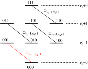
Step 2. A three-component broadband (BB) composite pulse is applied on each ion on the first blue sideband, i.e. pulses in total. This sequence is “seen” as a pulse by the transitions , where , and therefore the respective states in these transitions are inverted. This is illustrated for 3 ions in Fig. 1: if the transition with phonons “sees” a pulse (), then all transitions with will “see” (with very high fidelity) a pulse too. Then the collective internal states will be dressed with a different number of phonons conditional on the number of qubits in states and : a collective state with qubits in state () will be dressed with phonons. For 3 ions states and are mapped respectively to states and , states and are mapped respectively to states and , etc. Thus the collective states group into sets with the same number of phonons, and the same total number of internal excitations, as shown in Fig. 2. Note that after this step the state of each qubit is inverted, .
Step 3. A -component composite pulse sequence is applied on the target ion; this sequence is the core of our method. It must act in such a way that the transition “sees” an effective pulse and is inverted, while all other transitions “see” effectively a or pulse, i.e. remain either unchanged (for ) or all acquire the same phase (for ). (It turns out that the latter option is easier to realize.) Such a discrimination is made possible by step 2, because the couplings depend on the LD parameter and the number of phonons , which is different for the different sets Wineland98 ; Leibfried2003 ,
| (1) |
where is the generalized Laguerre polynomial. The different couplings produce different pulse areas, . Since two adjacent sets differ by 2 phonons we have to address the ions on the second blue vibrational sideband of a selected mode.
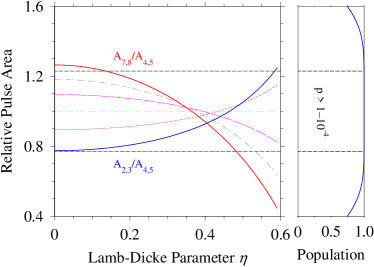
Consider a string of 3 ions needed for the Toffoli C2-NOT gate. To perform the Toffoli gate conditional on the states of ions 1 and 2 we address only ion 3 on the second blue sideband. The laser field then produces four separate two-state systems with different couplings, as shown in Fig. 2. We need a composite sequence, which is “seen” as a pulse by the transition but as a pulse by the other three transitions. Here the dependence of the couplings on the LD parameter is essential because the variation of allows us to find ranges where these conditions are fulfilled. For an initial phonon number the three subsystems in Fig. 2 have couplings , and . The dependence of the pulse area ratios and on are illustrated in Fig. 3(left). The range of values of where these ratios are near 2 are suitable for realization of the Toffoli gate, as indicated by the composite-pulse excitation profile in Fig. 3(right). One can vary the initial phonon number and produce different behavior of the relative pulse areas versus according to Eq. (1), which allows one to shift the -range for the Toffoli gate to the experimentally most convenient values.
Step 4. We repeat step 2 comment2 ; the phonon number in each collective internal state is restored to .
Step 5. Step 1 is applied in a reverse manner; the ion chain is restored in its vibrational ground state .
Steps 1-5 produce the transformation
| (2) |
with single pulses and a composite sequence. The number of pulses in the composite sequence from step 3 can vary, e.g., from 5 for C2-NOT (Toffoli) gate to 13 for C6-NOT gate, as shown below. Because the number of pulses in the composite sequence is about , the total number of pulses is about .
Our method generalizes the original idea of Monroe et al. Monroe1997 who constructed a CNOT gate by exploiting the -dependence of the LD parameter to select such a “magic” value of , for which the ratio of the two relevant couplings equals a rational odd/even or even/odd number. This approach cannot be extended with a single pulse to higher gates as they require specific values of the ratios of three or more couplings. We can satisfy these conditions in various -ranges because composite pulses can modify the excitation profile in any desired manner.
III Composite sequences for Cn-NOT gates
The technique of composite pulses was introduced in nuclear magnetic resonance (NMR) NMR ; Wimperis as a powerful tool for control of spins by magnetic fields. A composite pulse is a train of pulses with well-defined relative phases , which are used as control parameters in order to compensate the imperfections of a single pulse and/or to shape up the excitation profile in a desired manner. We have designed special composite pulses for the -NOT gates by using a recently developed simple method Ivanov2011 ; Torosov . We use equal pulse areas and an odd number of pulses, , although these restrictions are not essential. We consider symmetric “anagram” composite sequences, with phases ; this condition produces symmetric excitation profiles. Because the overall phase of the composite sequence is irrelevant we set ; hence we are left with different phases.
| standard NB pulses | |
|---|---|
| N5 | (1.160; 0.580) |
| N9 | (1.130; 0.820; 0.110; 1.390) |
| N13 | (1.270; 0.440; 1.020; 0.770; 1.850; 1.730) |
| N17 | (1.600; 0.550; 1.090; 0.890; 0.620; 1.540; 0.150; 1.570) |
| N21 | (1.070; 0.920; 0.130; 1.830; 1.160; 0.720; 0.100; 1.520; |
| 0.810; 1.950) | |
| N25 | (1.750; 0.380; 1.420; 0.710; 1.070; 0.910; 0.780; 1.470; |
| 0.550, 1.740, 0.160, 1.650) | |
| optimized NB pulses | |
| N | (1.190; 0.630) |
| N | (1.157; 0.888; 0.218; 1.529) |
| N | (0.585; 1.352; 0.914; 1.186; 0.020; 0.089) |
Three families of composite pulse sequences are particularly important: broadband (BB), narrowband (NB) and passband (PB) Wimperis . The BB pulses stabilize population inversion to values around the pulse area (flat-top excitation profile). The NB pulses stabilize to values around the pulse area (or ) (flat bottom). The PB pulses stabilize both to values around area and to values around area (or ) (flat-top and flat-bottom).
The composite phases for the BB sequence used in steps 2 and 4 are (0, 0.65, 0). Other examples of BB sequences can be found in Torosov .
In step 3 all but one of the couplings must fall in the region where , hence stabilization is needed around this value; the remaining coupling must fall in the range where , i.e. near . This condition suggests to use NB pulses because of their flat-bottom excitation profiles around areas and . None of the existing NB composite pulses, however, produces excitation profiles with sufficiently wide bottoms to satisfy these conditions with high fidelity; for this reason we construct here new NB composite sequences. We derive the NB phases from the conditions
| (3) |
with ; the skipped derivatives vanish identically for “anagram” sequences. is the full propagator, , with
| (4) |
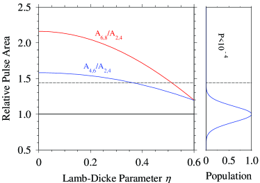
Examples of NB sequences suitable for Cn-NOT gates are presented in Table 1. A typical NB excitation profile is plotted in the right frame of Fig. 3. These NB sequences are “all-purpose” ones, i.e. they are suited whenever an increased selectivity of excitation, or suppression of unwanted excitation is needed, e.g. for local addressing in a lattice of closely spaced qubits Ivanov2011 . We have constructed special NB sequences which optimize the performance of the Cn-NOT gates; they are listed in Table 1 as well. Their phases are obtained by starting from a particular “all-purpose” NB pulse and minimizing the error in the high-fidelity region of the respective Cn-NOT gate in the control landscape. We can always accommodate more couplings (that have to be suppressed) within the no-transition bottom of the excitation profile around (and ) by adding more pulses to the composite sequence in order to broaden this bottom.
After the NB sequence the state of the target ion is changed as and , where
| (5) |
This phase can be compensated, if necessary, with an additional Stark pulse focused on the target ion.
IV Simulation of Cn-NOT gates
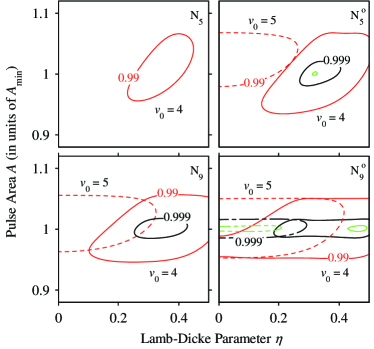
We have simulated numerically different Cn-NOT gates by using our approach presented above. The fidelity of the simulated gate is defined as the uniform average over infinitely many random states : . Figure 4 shows the fidelity of the Toffoli gate constructed with standard (left) and optimized (right) NB sequences from Table 1 for 5 (top) and 9 (bottom) ingredient pulses. Fidelity above 99%, and even 99.9%, can be obtained with just 5 pulses. Higher fidelity can be obtained with longer sequences, e.g. over 99.99% with the N pulse. The high-fidelity ranges can be varied by varying the initial phonon number , as evident from the examples with and 5 in Fig. 4: a larger shifts the high-fidelity -range toward .
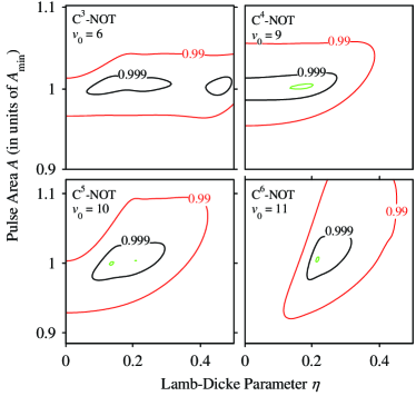
We have simulated several higher-order Cn-NOT gates with to 6 using the NB sequences from Table 1; the fidelities for the optimized NB pulse N are shown in Fig. 5. High fidelity can be achieved in various ranges of by changing the initial phonon number because the ratios of the couplings depend on both and ; larger push the high-fidelity range again toward smaller . In this manner, one can adjust the operation of the Cn-NOT gate to a range of values of , which is most suitable experimentally. Fidelity can always be increased, and the high-fidelity ranges can be expanded, by adding more pulses to the composite sequence, which will allow enhanced optimization. It is remarkable that the same composite pulse N implements all gates up to efficiently, in similar ranges of and . We have checked that this same pulse N can be used with over 99% fidelity for Cn-NOT gates up to . The lower gates with and 4 can be implemented efficiently also with the shorter pulse N (not shown), which has been used in Fig. 4. This uniformity is strikingly different from the circuit model, in which the complexity of implementation increases rapidly with , which makes the demonstration of most algorithms still impossible with current technology Blatt2009 . We have verified that, for up to , NB composite sequences of about ingredient pulses are sufficient for efficient construction of the Cn-NOT gate.
V Discussion and conclusion
The proposed method offers a conceptually simple and scalable implementation of Cn-NOT gates of trapped-ion qubits of arbitrary order , as it requires, besides the usual initial dressing and the final undressing of the collective qubit states with phonons, just a single NB pulse applied on the target ion qubit. This method uses the basic physical notion of destructive interference of unwanted transitions rather than quantum circuits of a vast number of concatenated one- and two-qubit gates. The ensuing simplicity and universality make our method easily scalable to arbitrary Cn-NOT gates with essentially the same level of complexity. The constructed NB sequences produce Cn-NOT gates with very high fidelity using relatively few ingredient pulses. We have found that a NB composite sequence of about pulses suffices for a Cn-NOT gate; including the dressing and undressing steps, the total number of pulses is about . This makes possible the creation of Cn-NOT gates for up to ion qubits with the existing ion trap technology Monz2011 . We point out that the NB composite sequences are very convenient in another respect: they eliminate spatial imperfections of local addressing Ivanov2011 , which are often a limiting factor in experiments Blatt2009 .
We note that the use of blue-sideband pulses is not mandatory; one can use red-sideband pulses too. One can also replace the NB composite sequences, which minimize the number of ingredient pulses, by PB sequences, which require a few more ingredient pulses but provide in return greater robustness against variations in the pulse area.
We point out in conclusion that the initial dressing of the qubit states with phonons and the final restoration of the phonon ground state, each of which requires about pulses, can be optimized for each Cn-NOT gate to fewer pulses, about for each of the dressing and undressing steps IvanovUnpublished . The procedure described above is, however, universal (applicable to arbitrary ) and flexible, for it applies to large ranges of values of the LD parameter ; the latter feature allows one to operate outside the LD regime and hence speed up the gate operation.
This work is supported by the European Commission project FASTQUAST and the Bulgarian NSF grants D002-90/08 and DMU02-19/09.
References
- (1) D. G. Cory et al., Phys. Rev. Lett. 81, 2152 (1998).
- (2) Y. Shi, Quantum Inform. Comput. 3, 84 (2003).
- (3) M. A. Nielsen and I. L. Chuang, Quantum Computation and Quantum Information (Cambridge University Press, Cambridge, 2000).
- (4) A.P. Hines and P.C.E. Stamp, Phys. Rev. A 75, 062321 (2007).
- (5) B. P. Lanyon et al., Nature Phys. 5, 134 (2009).
- (6) M. Borrelli et al., arXiv:1012.1723.
- (7) T. Monz et al., Phys. Rev. Lett. 102, 040501 (2009).
- (8) This does not necessarily impose the LD regime, which is accessed when both the phonon number and the LD parameter are very small.
- (9) D.Wineland et al., J. Res. Natl. Inst. Stand. Technol. 103, 259 (1998).
- (10) D. Leibfried et al., Rev. Mod. Phys 75, 281 (2003).
- (11) One can shift all phases with relative to step 2 to compensate possible experimental errors of steps 2 and 4.
- (12) C. Monroe et al., Phys. Rev. A 55, R2489 (1997); B. DeMarco et al., Phys. Rev. Lett. 89, 267901 (2002).
- (13) M.H. Levitt and R. Freeman, J. Magn. Reson. 33, 473 (1979); M.H. Levitt, Prog. NMR Spectrosc. 18, 61 (1986); R. Freeman, Spin Choreography (Spektrum, Oxford, 1997).
- (14) S. Wimperis, J. Magn. Reson. 109, 221 (1994).
- (15) S. S. Ivanov and N. V. Vitanov, Opt. Lett. 36, 7 (2011).
- (16) B. T. Torosov and N. V. Vitanov, Phys. Rev. A 83, 053420 (2011).
- (17) T. Monz et al., Phys. Rev. Lett. 106, 130506 (2011).
- (18) S. S. Ivanov and N. V. Vitanov, unpublished.