Mechanisms of nonlinear spin-wave emission from a microwave driven nanocontact
Abstract
We present a micromagnetic study of linear and nonlinear spin-wave modes excited in an extended permalloy thin film by a microwave driven nanocontact. We show that the linear mode having the frequency equal to the excitation frequency (f) is driven by the ac Oersted field component perpendicular to the static external field (applied in-plane of the sample). The nonlinear mode with the frequency f/2 is excited as an independent eigenmode within a parametric longitudinal pumping process (due ac Oersted field component parallel to the bias field). Spectral positions of those modes are determined both in the space and phase domain. The results are important for the transfer of information coded into spin-waves between nanocontacts, and for synchronization of spin transfer torque nano-oscillators.
- PACS numbers
-
75.30.Ds, 75.78.Cd, 75.75.+a
pacs:
75.30.Ds, 75.78.CdSpin waves in meso- and micro-sized magnetic structures have attracted growing attention due to the prospective applications in magnon spintronic devices. For example, the use of phase and amplitude of spin waves as an information carrier in magnetic logic circuits is extensively studied.Kostylev ; Kim ; Schneider ; Khitun The problem of spin-wave excitation is of crucial importance for the miniaturization of such devices to the nano-scale. The advanced research on device miniaturization makes it possible to study the spin waves exited by microwave driven nanosized antennas (nanocontacts). Tsoi ; Demidov ; Schultheiss ; Balkashin This task is not trivial: if the density of the microwave current is high enough, the spin-wave system is pushed far beyond the linear regime, and nonlinear processes appear. Moreover, in nano-sized structures, the properties like the threshold power and frequency limit of the nonlinear excited spin-wave modes can be tuned by a superimposed direct current flowing through the contact.Schultheiss Vice versa, the influence of the microwave currents on the magnetic oscillations caused by the spin transfer torque effect (STT) in direct current driven nanocontacts was demonstrated.Rippard ; Florez It was shown that the propagation length of the STT emitted spin waves can be enhanced by using an additional microwave current injected through the contact.Demokritov The microwave current plays also an important role in the synchronization of STT based nano-oscillators (STNO).Rippard ; Georges ; Urazhdin All these tasks need a deeper understanding of the characteristics of spin waves emitted by microwave driven nanocontacts.
In this work we performed systematic micromagnetic simulations OOMMF on magnetization dynamics in a nanocontact structure to reveal the underlaying mechanism of magnons excitation and to characterize the linear and nonlinear spin-wave modes detected experimentally in such devices.Schultheiss
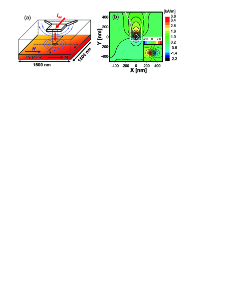
In the simulations we considered a thin permalloy layer of 7 nm thickness with lateral dimensions of m2 (see Fig. 1(a)). As in the experiment Schultheiss , an in-plane magnetic field of 19.89 kA/m (250 Oe) was applied along the -axis. A microwave current is injected through the nanocontact placed in the center of the structure as defined in Fig. 1(a). The resulting alternating Oersted field excites magnetization precession in the system. The circular shape contact has a diameter of 100 nm. The standard material parameters of permalloy used to simulate the magnetization dynamics are: saturation magnetization T, exchange stiffness constant J/m and zero magnetocystalline anisotropy was assumed. The simulated area was discretized into cells, each cell having a size of nm3. Initially, the magnetization is aligned in-plane along the -axis. To model the parametric processes in our system, we considered a random fluctuation of the magnetization within 0.5∘ with respect to the -axis, which is caused by thermal noise in real systems. The damping boundary conditions were used to avoid spin-wave reflection at the edges of the simulation area. A spatial distribution of the damping parameter () in the Landau-Lifshitz-Gilbert equation (with the STT term included) given by: with , nm, and nm ensures a constant value in the center of the sample for a radius of nm. The variables and denote the spatial coordinates. With the above parameters, the damping is increased more than fifty times at the edges of the simulation area, thus the spin-wave intensity decays strongly towards the boundaries. We calculate LLG the current distribution and the corresponding Oersted field in the Permalloy layer with and without the contribution of an asymmetric top electrode (according to the real structure in the experiment Schultheiss ). It was found that the lead induces an asymmetry for the Oersted field component parallel to the external field while the perpendicular component remains virtually unchanged (Fig. 1(b)). In the presented simulations we used the distribution of the Oersted field with the contribution of the lead included.
From the experiment Schultheiss it was found that two conditions must be fulfilled in order to generate a spin-wave mode with half of the excitation frequency. Firstly, the excitation frequency must be at least twice the frequency at the bottom of the spin-wave dispersion band (noted ), and secondly, the applied microwave power is above a certain threshold value. In our configuration GHz, we set the excitation frequency to 11 GHz to satisfy the first condition. The exact value for the threshold power could not be determined by simulations due to extremely long computation times. We used an applied microwave power sufficiently large in order to observe the nonlinear excited spin waves with good contrast.
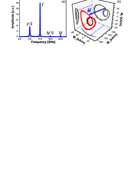
Analyzing the magnetization fluctuation in time for each computational cell and performing the Fast Fourier Transform (FFT), we obtained the frequency spectra for each component of the magnetization. The behavior of the magnetization in one computational cell (top edge of the contact) is presented in Fig. 2. One sees a response with the same frequency as the excitation one (f), but also the generation of nonlinear modes: 0.5f, 1.5f and 2f (Fig. 2(a)). Furthermore, the precession of the magnetization vector tip has a steady complicated trajectory when the nonlinear modes are generated (see Fig. 2(b)), different from typical clamshell orbits found in thin films for linear excitations. An additional small loop was observed on the main gyration motion. This peculiarity originates from the combination of partial magnetization motions at different frequencies.
Our main task is to identify the excitation mechanism, spatial localization and the wavevector directions as well as wave numbers for both linear and nonlinear excited spin-waves modes.
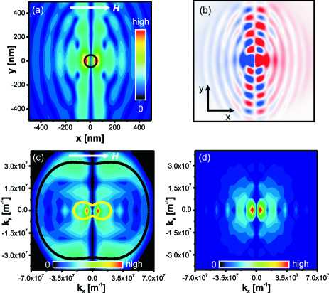
First, we address the generation of the linear mode for which the frequency matches the microwave one (f). The spatial distribution is obtained by taking the amplitude value at f = 11 GHz from the frequency spectra of each computational cell and displaying them as a function of the position. The obtained map is shown in Fig. 3(a). The black circle in the center represents the position of the nanocontact. One can observe two maxima that are located on the left and right side edges of the contact. This can be understood by taking into account that the main driving field at the excitation frequency is the Oersted field component perpendicular to the bias field, with a very similar amplitude distribution in space (see the inset from Fig. 1(a)). From Fig. 3(a), we identified two types of waves excited by the nanocontact: travelling and non-propagating waves. The travelling spin waves exhibit in four beams starting from those two maxima regions, and are propagating along directions nearly perpendicular to the bias field (applied on the -axis), while the non-propagating ones can be observed in the rest of space. Moreover, the two maxima regions are acting as two independent sources which emit spin waves out of phase (180∘) in respect to each other. This is illustrated on the snapshot image of the magnetization oscillation pattern in the entire permalloy layer (Fig. 3(b)) with the component color coded. Since the two spin-wave beams that are travelling on the same side of the contact (up or down) are out of phase, a destructive interference takes place between them. Consequently, the spin-wave intensity is strongly reduced on the direction perpendicular to the bias field in the center of the contact (Figs. 3(a) and 3(b)).
The wavevectors of the emitted spin waves are determined by applying the two-dimensional Fourier transform in space to the already calculated components (real and imaginary parts) of the temporal FFT for each computational cell. Figure 3(c) shows the distribution of the f mode in the wavevector space. and axis are the wave numbers that indicate the in-plane directions of propagation parallel and perpendicular to the external applied magnetic field, respectively. The black and yellow contours in the figure represent the analytical constant-frequency curve calculated from the dispersion relation Kalinikos for a frequency of 11 GHz and 5.5 GHz, respectively. The wavevector data obtained from the simulation is in very good agreement with the analytical constant-frequency curve calculated at 11 GHz (the black line in the figure).
The analysis in the wavevector space (Fig. 3(c)) shows that indeed the most efficiently excited spin waves are the ones that are propagating with wavevectors nearly perpendicular with respect to the bias field. The excitation efficiency is decreasing fast with the spin-wave propagation angle, becoming close to zero for spin waves with wavevectors parallel to the bias field. This is associated with the known effect of decreasing excitation efficiency for spin-waves with short wavelengths. Nevertheless, the extracted data from the simulation shows another two strong maxima located at small wave numbers. Those maxima are related to the forced non-resonant driving of magnetization by the excitation field. Their location is traced back to the spatial configuration of the driving ac field. Figure 3(d) presents the distribution of the perpendicular component of the Oersted field computed in the wavevector space. By comparing these distributions (magnetization and excitation field) one observes that the maxima are located at the same wave numbers. Thus, one can see that the perpendicular component of the driving Oersted field is responsible for excitation of both propagating and localized spin-wave modes at the signal frequency f. The excitation efficiency for travelling waves reaches the maximum at directions perpendicular to the bias field.
Next we discuss the process of excitation and the characterization of the non-linear spin-wave modes, especially the f/2 mode, is described in the second part of the article.
The appearance of the f/2 mode (= 5.5 GHz), can be potentially attributed to three different excitation mechanisms. Mechanism 1 is related to the three-magnon scattering process (confluence and splitting of magnons - quanta of the spin waves which are eigenexcitation of the magnetic system). Within mechanism 2, the component of the driving Oersted field excites an ac magnetization perpendicular to the bias field. This ac magnetization serves as a pump for the f/2 mode, via the so-called process of parametric excitation of spin waves under perpendicular pumping. Within this process, the f/2 mode can be generated directly from the forced excitation of magnetization at the frequency f. Mechanism 3 is a direct excitation of the f/2 mode by the Oersted field component parallel to the bias field, a process called longitudinal (or parallel) parametric pumping.Melkov
The radiation pattern extracted from the simulation for the f/2 mode is presented in Fig. 4(a). The black circle indicates the position of the nanocontact. One can observe that the f/2 mode is localized outside the contact area in the corresponding regions of travelling spin waves for the directly excited f mode. This observation may suggest that we are dealing with a splitting of magnons of the f mode. The law of energy conservation for such processes is fulfilled since any mode could be obtained as a combination (confluence or splitting) of the other modes (see Fig. 2(a)). However, it has to be noted that the wave numbers extracted from the magnetization intensity distributions in the phase space for both f and f/2 (Fig. 3(c) and Fig. 4(b)) modes do not fulfill the momentum conservation law. Moreover, from the constant-frequency curves calculated analytically for 11 GHz and 5.5 GHz (black and yellow curves from Fig. 3(c)) one sees that the conservation of momentum during the splitting process is not satisfied for any combination of wavevectors. In other words, there is no pair of wavevectors at the frequency of f/2 = 5.5 GHz that can combine into one corresponding to 11 GHz, or vice versa. This strongly contradicts the assumption that three-magnon scattering processes take place in the given configuration, ruling out mechanism 1. The analysis in the phase space of the f/2 mode (displayed in Fig. 4(b)) shows a propagation of spin waves with wavevectors under a maximum angle of 15∘ with respect to the bias field (-direction). The asymmetry is related to additional contributions of the lead to the internal field (similar for the asymmetry in the radiation pattern from Fig. 4(a)).
In order to discriminate between mechanism 2 and 3 for the f/2 mode generation (perpendicular and parallel parametric pumping), we performed two additional simulations, in each one taking into account only one component of the Oersted field, and , respectively. The applied power was kept at the same value as previously.
By applying only the perpendicular component , the qualitative behavior for the f mode remains virtually unchanged in both space and phase domain. Practically no difference was observed in comparison with the two distributions presented in Fig. 3(a) and Fig. 3(c). This confirms that the f mode derives from the perpendicular component of the ac Oersted field. However, from the frequency spectra (red curve in Fig. 4(c)) it was observed that the f/2 mode had vanished. Even if the pumping power was doubled, no peak was seen at the corresponding frequency for the f/2 mode. Therefore, one can conclude that perpendicular parametric pumping (mechanism 2) is not responsible for the generation of the f/2 mode. Also, it evidences that the splitting of magnons does not occur even if there is a strong excitation of the f mode.
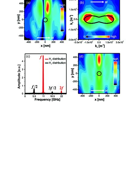
In the longitudinal parametric pumping process (mechanism 3), the magnetization is excited by an ac field parallel to the steady one. Within this process, spin waves having half of the excitation frequency are amplified directly from the thermal bath. The frequency spectra obtained from the simulation (black line in Fig. 4(c)) show two peaks corresponding to the f/2 and 3f/2 modes and no intensity for the f mode. The spatial distribution of the f/2 mode is presented in Fig. 4(d). Two maxima are observed and are consistent with the spatial distribution of the excitation field (only component). The strong asymmetry is derived from the additional field created by the lead on top of the sample. One can notice that the intensity distribution of the f/2 mode obtained in this case is very similar to the one resulting when both components of the Oersted field were taken into account (Fig. 4(a)). Moreover, the analysis of the f/2 mode in the phase space shows exactly the same distribution of the wave numbers as was found when both and components were considered (Fig. 4(b)). The slight shift observed by comparing the two magnetization distributions from Fig. 4(a) and Fig. 4(c) can be interpreted as a distortion caused by the travelling waves of the f mode on the f/2 mode. Altogether, this shows clearly that the f/2 mode is excited as an independent eigenmode by parametric longitudinal pumping.
In conclusion, we performed a micromagnetic study of the linear and nonlinear spin-wave modes excited by microwave currents in a nanocontact structure. We have shown that the dominant spin-wave mode is driven by the dynamical Oersted field component perpendicular to the static external field. The nonlinear f/2 mode derives from the parametric longitudinal pumping effect (due alternating Oersted field component parallel to the bias field). Spectral positions of those modes are determined both in the space and frequency domains. The f mode emitted from the points localized at edge of the contact is propagating nearly perpendicular to the bias field. The f/2 mode is localized outside the contact area and is propagating under a small angle with respect to the steady field. These results are important for the realization of nano-sized spin-wave antennas in magnon based spintronic devices and can be used for the design of spin-wave coupled arrays of nano-oscillators.
This work was supported by the European Commission within the EU-MRTN SPINSWITCH (MRTN-CT-2006- 035327). We also thank A. Slavin, V. Tiberkevich and M. Kostylev for fruitful discussions.
References
- (1) M.P. Kostylev, A.A. Serga, T. Schneider, B. Leven, and B. Hillebrands, Appl. Phys. Lett. 87, 153501 (2005). Spin-wave logical gates
- (2) K.S. Lee and S.K. Kim, J. Appl. Phys. 104, 053909 (2008). Conceptual design of spin wave logic gates based on a Mach Zehnder-type spin wave interferometer for universal logic functions
- (3) T. Schneider, A.A. Serga, B. Leven, B. Hillebrands, R.L. Stamps, and M.P. Kostylev, Appl. Phys. Lett. 92, 022505 (2008). Realization of spin-wave logic gates
- (4) A. Khitun, M. Bao, K.L. Wang, IEEE Trans. Magn. 144 (9), 2141-2152 (2008). Spin Wave Magnetic NanoFabric: A New Approach to Spin-Based Logic Circuitry
- (5) M. Tsoi, A.G.M. Jansen, J. Bass, W.-C. Chiang, V. Tsoi, and P. Wyder, Nature 406, 46 (2000). Generation and detection of phase-coherent current-driven magnons in magnetic multilayers
- (6) V.E. Demidov, S.O. Demokritov, G. Reiss and K. Rott, Appl. Phys. Lett. 90, 172508 (2007). Effect of spin-polarized electric current on spin-wave radiation by spin-valve nanocontacts
- (7) O.P. Balkashin, V.V. Fisun, I.K. Yanson, L.Yu. Triputen, A. Konovalenko and V. Korenivski, Phys. Rev. B 79, 092419 (2009). Spin dynamics in point contacts to single ferromagnetic films
- (8) H. Schultheiss, X. Janssens, M. van Kampen, F. Ciubotaru, S.J. Hermsdoerfer, B. Obry, A. Laraoui, A.A. Serga, L. Lagae, A.N. Slavin, B. Leven, and B. Hillebrands, Phys. Rev. Lett. 103, 157202 (2009). Direct Current Control of Three Magnon Scattering Processes in Spin-Valve Nanocontacts
- (9) W.H. Rippard, M.R. Pufall, S. Kaka, T.J. Silva, S.E. Russek, and J.A. Katine, Phys. Rev. Lett. 95, 067203 (2005). Injection Locking and Phase Control of Spin Transfer Nano-oscillators
- (10) S.H. Florez, J.A. Katine, M. Carey, L. Folks, O. Ozatay, and B.D. Terris, Phys. Rev. B 78, 184403 (2008). Effects of radio-frequency current on spin-transfer-torque-induced dynamics
- (11) V.E. Demidov, S. Urazhdin, V. Tiberkevich, A. Slavin,and S.O. Demokritov, Phys. Rev. B 83, 060406(R) (2011). Control of spin-wave emission from spin-torque nano-oscillators by microwave pumping
- (12) B. Georges, J. Grollier, M. Darques, V. Cros, C. Deranlot, B. Marcilhac, G. Faini, and A. Fert, Phys. Rev. Lett. 101, 017201 (2008). Coupling Efficiency for Phase Locking of a Spin Transfer Nano-Oscillator to a Microwave Current
- (13) S. Urazhdin, P. Tabor, V. Tiberkevich and A. Slavin, Phys. Rev. Lett. 105, 104101 (2010). Fractional Synchronization of Spin-Torque Nano-Oscillators
- (14) The simulations were performed using the OOMMF open code: M.J. Donahue, and D.G. Porter, Report NISTIR 6376, National Institute of Standards and Technology, Gaithersburg, MD (1999).
- (15) The micromagnetic simulation software LLG Micromagnetics developed by M.R. Scheinfein.
- (16) B.A. Kalinikos and A.N. Slavin, J. Phys. C 19, 7013 (1986)
- (17) A.G. Gurevich and G.A. Melkov, Magnetization Oscillations and Waves. Boca Raton, FL: CRC (1996).