Two-photon- photoluminescence excitation spectroscopy of single quantum-dots
Abstract
We present experimental and theoretical study of single semiconductor quantum dots excited by two non-degenerate, resonantly tuned variably polarized lasers. The first laser is tuned to excitonic resonances. Depending on its polarization it photogenerates a coherent single exciton state. The second laser is tuned to biexciton resonances. By scanning the energy of the second laser for various polarizations of the two lasers, while monitoring the emission from the biexciton and exciton spectral lines, we map the biexciton photoluminescence excitation spectra. The resonances rich spectra of the second photon absorption are analyzed and fully understood in terms of a many carrier theoretical model which takes into account the direct and exchange Coulomb interactions between the quantum confined carriers.
pacs:
Valid PACS appear hereI Introduction
Semiconductor quantum dots (QDs) confine charge carriers in three spatial directions. This confinement results in discrete spectrum of energy levels and energetically sharp optical transitions between these levels M. Ediger, G. Bester, A. Badolato, P. M. Petroff, K. Karrai, A. Zunger, R. J. Warburton (2007); E. Poem, J. Shemesh, I. Marderfeld, D. Galushko, N. Akopian, D. Gershoni, B. D. Gerardot, A. Badolato, P. M. Petroff (2007). These “atomic-like” features, together with their compatibility with modern semiconductor based microelectronics and optoelectronics, make QDs promising building block devices for future technologies involving single-photon emitters P. Michler, A. Kiraz, C. Becher, W. V. Schoenfeld, P. M. Petroff, L. Zhang, E. Hu, A Imamoglu (2000) and quantum information processing (QIP) P. Zanardi, F. Rossi (1998); A. Imamoḡlu, D. D. Awschalom, G. Burkard, D. P. DiVincenzo, D. Loss, M. Sherwin, A. Small (1999); D. Press, K. De Greve, P. L. McMahon, T. D. Ladd, B. Friess, C. Schneider, M. Kamp, S. H¨fling, A. Forchel, Y. Yamamoto (2010). In particular, QDs are considered to be an excellent interface between photons, whose polarization state may carry quantum information from one site to another, and confined carriers’ spins, whose states can be coherently manipulated locally H. Kosaka, T. Inagaki, Y. Rikitake, H. Imamura, Y. Mitsumori, K. Edamatsu1 (2009); Y. Benny, S. Khatsevich, Y. Kodriano, E. Poem, R. Presman, D. Galushko, P. M. Petroff, D. Gershoni (2011). For these reasons, it is very important to study and to understand in detail light-matter interactions in such nanostructures. Deep understanding of these interactions is required in order to implement protocols and schemes relevant to QIP D. P. DiVincenzo (1995), in these man-made, technology compatible, ‘artificial atoms’.
In this work we present a comprehensive study of single, neutral semiconductor QDs subject to excitation by two different variably polarized resonant lasers. The first laser is tuned to an excitonic resonance and generates a coherent single exciton state, while the second laser is scanned through biexcitonic resonances. Depending on the particular resonance and the direction of the light polarization relative to the direction of the exciton spin, it photogenerates a biexciton Y. Benny, S. Khatsevich, Y. Kodriano, E. Poem, R. Presman, D. Galushko, P. M. Petroff, D. Gershoni (2011). The absorption is then monitored through the emission intensities of various biexcitonic and excitonic spectral lines.
The manuscript is organized as follows: Section II is devoted to set the theoretical background which is required to analyze the experimental data. In section III we describe the experimental methods and the measurements that we performed. In section IV we present the experimental results and analyze the data, using the theory outlined in section II. The last part of this section provides a short summary of the results.
II Theory
We use a simple one-band model to describe the single-particle wavefunctions of electrons in the conduction band and heavy-holes in the valence band of a single QD. Since in these InAs/GaAs lattice mismatch strain induced self-assembled QDs, the light-holes band is energetically separated from the heavy-hole band by the strain and the quantum size effect, light holes are not considered in our model. The lateral extent of these QDs is typically about an order of magnitude larger than their extent along the growth direction. Therefore, for simplicity, our model considers only the two lateral directions. The exact composition and strain distribution in these QDs are not accurately known, therefore we use a very simple, two dimensional parabolic potential model to describe the QD influence on the carriers that it confines. This simple model is general enough to describe the symmetry of these QDs R. Singh, G. Bester (2010), and it contains four parameters (see below) which permit its adjustment to the experimental observations E. Poem, J. Shemesh, I. Marderfeld, D. Galushko, N. Akopian, D. Gershoni, B. D. Gerardot, A. Badolato, P. M. Petroff (2007). Two separated infinite elliptic parabolic potentials are thus used, one for the electrons and one for the heavy-holes R. J. Warburton, B. T. Miller, C. S. Dürr, C. Bödefeld, K. Karrai, J. P. Kotthaus, G. Medeiros-Ribeiro, P. M. Petroff, S. Huant (1998). The resulting envelope wavefunctions or orbitals of the carriers, are therefore described analytically by the 2D harmonic solutions:
| (1) |
where p=e(h) stands for electron (heavy-hole) and are the Hermite polynomials of order .
| (2) |
is a characteristic length, which describes the extent of the parabolic potential along the direction and Eq. 2 relates this length to the charge carrier’s in-plane effective mass and the harmonic potential inter-level energy separation . We fit the four characteristic lengthes to best describe the observed spectral lines.
Equipped with the single carrier’s eigenenergies and envelope wavefunctions we proceed by calculating the many-carrier energies and states using configuration interaction (CI) model A. Barenco, M. A. Dupertuis (1995); E. Dekel, D. Gershoni, E. Ehrenfreund, J. M. Garcia, P. M. Petroff (2000); E. Poem, J. Shemesh, I. Marderfeld, D. Galushko, N. Akopian, D. Gershoni, B. D. Gerardot, A. Badolato, P. M. Petroff (2007). A detailed description of the model, which takes into account the direct and exchange Coulomb interactions between any pair of carriers in the QD, is presented elsewhere E. Poem, J. Shemesh, I. Marderfeld, D. Galushko, N. Akopian, D. Gershoni, B. D. Gerardot, A. Badolato, P. M. Petroff (2007).
Previous studies dealt mainly with optical transitions to ground excitonic states as a tool to describe polarization sensitive photoluminescence (PL) experiments E. Poem, J. Shemesh, I. Marderfeld, D. Galushko, N. Akopian, D. Gershoni, B. D. Gerardot, A. Badolato, P. M. Petroff (2007); M. Ediger, G. Bester, A. Badolato, P. M. Petroff, K. Karrai, A. Zunger, R. J. Warburton (2007). Here, motivated by our progress in performing resonant PL excitation (PLE) spectroscopy, using one and two laser sources, we use the same model to consider transitions from various other levels. First, we consider transitions which result from the resonant absorption of one photon. Then, we add a second photon, resonantly tuned to the resonances of the optically excited QD. Since, as we explain below, the situation in this case is much richer than for PL only, we have to modify the notation for describing the QD many-carrier states. We use the following notation; A single carrier state is described by its envelope wavefunction or orbital mode (O=1,2,…,6), where the number represents the energy order of the level so that O=1 represents the ground state. O is followed by the type of carrier, electron (e) or heavy-hole (h) and a superscript which describes the occupation of the single carrier state. The superscript can be either 1 (open shell) or 2 (closed shell), subject to the Pauli exclusion principle (non occupied states are not described). All the occupied states of carriers of same type are then marked by subscripts which describe the mutual spin configuration () of these states.
II.1 Characterization of excitonic resonances
The ground exciton state [] is a two-carrier state, formed mainly by one electron and one heavy-hole in their respective ground states. The exchange interaction between the electron and the heavy-hole M. Bayer, G. Ortner, O. Stern, A. Kuther, A. A. Gorbunov, A. Forchel, P. Hawrylak, S. Fafard, K. Hinzer, T. L. Reinecke, S. N. Walck, J. P. Reithmaier, F. Klopf, F. Schäfer (2002); T. Takagahara (2000); E. Poem, J. Shemesh, I. Marderfeld, D. Galushko, N. Akopian, D. Gershoni, B. D. Gerardot, A. Badolato, P. M. Petroff (2007) is described, using the method of invariants E. L. Ivchenko, G. E. Pikus (1997), by the following spin Hamiltonian M. Bayer, G. Ortner, O. Stern, A. Kuther, A. A. Gorbunov, A. Forchel, P. Hawrylak, S. Fafard, K. Hinzer, T. L. Reinecke, S. N. Walck, J. P. Reithmaier, F. Klopf, F. Schäfer (2002):
| (3) |
where () denotes the cartesian component of the electron (hole) spin and and are spin-spin coupling constants. The total spin projection on the direction is thereby given by . Here as well, the interaction with light-holes is neglected so that in only heavy-hole spins are considered M. Bayer, G. Ortner, O. Stern, A. Kuther, A. A. Gorbunov, A. Forchel, P. Hawrylak, S. Fafard, K. Hinzer, T. L. Reinecke, S. N. Walck, J. P. Reithmaier, F. Klopf, F. Schäfer (2002). In matrix form, for the basis :
|
(4) |
where () indicates spin-up (-down) electron (heavy-hole) in the orbital , the Hamiltonian is given by
| (5) |
where , and M. Bayer, G. Ortner, O. Stern, A. Kuther, A. A. Gorbunov, A. Forchel, P. Hawrylak, S. Fafard, K. Hinzer, T. L. Reinecke, S. N. Walck, J. P. Reithmaier, F. Klopf, F. Schäfer (2002). are three constants, which fully characterize the exchange interaction between the carriers in the ground states E. L. Ivchenko, G. E. Pikus (1997). It is clearly seen that in a symmetry the exchange interaction completely removes the degeneracy between the four possible various combinations of the electron-hole pair spin states R. Singh, G. Bester (2010). The eigen-energies and the eigenstates are schematically described in Fig. 1. The lowest energy state is the symmetric dark exciton state which in our notation is described as follows: . above it lies the anti-symmetric dark exciton state: . , is known to be quite small and believed to be orbit independent E. L. Ivchenko, G. E. Pikus (1997). It was recently measured from the temporal period of the coherent precession of the dark exciton spin to be 1.4 E. Poem, Y. Kodriano, C. Tradonsky, N. H. Lindner, B. D. Gerardot, P. M. Petroff, D. Gershoni (2010).
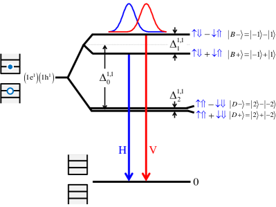
The bright exciton eigenstates in which the electron and heavy-hole spins are anti-aligned lie above the dark exciton states. The isotropic e-h exchange, , was previously found to be about 300 , by magneto-optical measurements S. Alon-Braitbart, E. Poem, L. Fradkin, N. Akopian, S. Vilan, E. Lifshitz, E. Ehrenfreund, D. Gershoni, B. D. Gerardot, A. Badolato, P. M. Petroff (2006).
The symmetric and antisymmetric bright exciton states , are split by the anisotropic e-h exchange, . The magnitude and sign of , is directly measured by polarization sensitive PL spectroscopy. Since is negative, the antisymmetric state () is higher in energy than the symmetric one () T. Takagahara (2000); E. Poem, J. Shemesh, I. Marderfeld, D. Galushko, N. Akopian, D. Gershoni, B. D. Gerardot, A. Badolato, P. M. Petroff (2007).
Conservation of angular momentum dictates that when a () e-h pair radiatively recombines, a right- (left-) hand circularly polarized photon is emitted. It follows that radiative recombination from the symmetric (antisymmetric) bright exciton state is linearly polarized H (V) along the major (minor) in-plane axis of the QD E. L. Ivchenko, G. E. Pikus (1997); D. Gammon, E. S. Snow, B. V. Shanabrook, D. S. Katzer, D. Park (1996). We note that the symmetric and antisymmetric dark and bright exciton states are by no means unique to the first single carrier spatial levels (Oe=Oh=1). In fact, similar bright and dark excitonic states are formed for any combination of Oe and Oh single carrier states. In general, depend on the orbital mode of the carriers T. Takagahara (2000); E. Poem, J. Shemesh, I. Marderfeld, D. Galushko, N. Akopian, D. Gershoni, B. D. Gerardot, A. Badolato, P. M. Petroff (2007).
When the laser is resonantly tuned into one of the excited bright exciton states and its light is polarized correctly, the light is absorbed and a single electron-hole pair is photogenerated. For example, let us consider the states: . These states are similar to the ground bright states , albeit, here the hole is in its second orbital mode (). Electron and hole pair will be photogenerated in these levels, and then the hole will rapidly relax non-radiatively (within 20 psec E. Poem, Y. Kodriano, C. Tradonsky, B. D. Gerardot, P. M. Petroff, D. Gershoni (2010); Y. Kodriano, E. Poem, N. H. Lindner, C. Tradonsky, B. D. Gerardot, P. M. Petroff, J. E. Avron, D. Gershoni (2010)), by emitting phonons, to the ground level (). This relaxation is faster than the radiative recombination rate (1 nsec).
Experimental identification of single photon or single exciton transitions is conventionally done by polarization sensitive PL and PLE spectroscopies. In PL, a QD is optically excited. The excitation gives rise to light emission from various long-lived states which do not relax to lower energy states within their radiative lifetime. Polarization and intensity sensitive PL spectroscopies are in particular useful for these identifications. For example, the bright exciton typically gives rise to PL doublet composed of two cross-linearly polarized components. These components are due to recombination from each of its non-degenerate eigenstates.
The second orbital wavefunction () has one node along the major symmetry axis of the QD. As a result is positive and therefore the symmetric eigenstate is higher in energy than the anti-symmetric eigenstate T. Takagahara (2000). It thus follows that the V linearly polarized transition to this exciton is lower in energy than the H polarized one. When the () state is excited, the hole rapidly relaxes non-radiatively to its ground state, releasing its energy into acoustical phonons. Since phonons do not interact with the carriers’ spin E. Poem, Y. Kodriano, C. Tradonsky, B. D. Gerardot, P. M. Petroff, D. Gershoni (2010); Y. Benny, S. Khatsevich, Y. Kodriano, E. Poem, R. Presman, D. Galushko, P. M. Petroff, D. Gershoni (2011); Y. Kodriano, E. Poem, N. H. Lindner, C. Tradonsky, B. D. Gerardot, P. M. Petroff, J. E. Avron, D. Gershoni (2010), the spin wavefunction’s symmetry remains the same, and the recombination occurs from the () state. Thus, polarization sensitive PLE spectroscopy can be efficiently used to identify and sort various excitonic resonances.
II.2 Characterization of biexcitonic resonances
The ground biexciton state is formed mainly by two spin paired electrons and two spin paired heavy-holes in their respective ground states. In our notation this state is described as follows: . We note that spin paired carriers can only form an antisymmetric spin singlet state and therefore the subscripts in this case is redundant and it is omitted from the pair’s state description. For unpaired carriers, however, the situation is different. Two unpaired carriers can form either a one antisymmetric singlet state, or three symmetric triplet states. Therefore, in this case we do assign subscripts for describing the unpaired carriers’ wavefunctions. For two unpaired carriers the can either be S, to indicate a singlet state, or , to indicate a triplet state. Here m is the total spin projection, 0 or (0 or ) of the pair of electrons (heavy-holes), along the QD growth direction. A full description of a state with two unpaired electrons and two unpaired holes has therefore the form
| (6) |
We note that for a given set of 4 unpaired spatial coordinates, 16 different states with different spin configurations are possible. These are naturally divided into the following 4 subgroups; One state, similar in nature to the ground biexciton state, in which the two electrons form a singlet (e-singlet) and the two heavy-holes also form a singlet (h-singlet). Three states in which the electrons form an e-singlet and the holes triplet (h-triplet), three in which the holes form a h-singlet and the electrons e-triplet and nine in which both the electrons and holes form triplets (e-triplet-h-triplet). These four subgroups have different energies due to the exchange interactions between carriers of same charge. The lowest energy level includes the 9 e-triplet-h-triplet states, the two intermediate groups include the 6 e-triplet-h-singlet and e-singlet-h-triplet states and the highest energy one includes only a single e-singlet-h-singlet state.
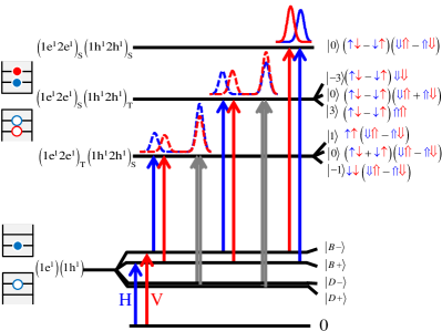
For simplicity, we begin by characterizing optical transitions in which at least one type of carriers forms a singlet. In Fig. 2 we schematically describe the energy levels and the spin wavefunctions of the configuration , for the cases , or . The major parts of the spin wavefunctions are described to the right of each level, where () represents an electron (hole) with spin up (down) and a blue (red) arrow represents a carrier in its first (second) level. The bracketed numbers stand for the total spin of the configuration. H (V) polarized optical transitions are represented by blue (red) vertical arrows.
We note that singlet-triplet and singlet-singlet biexcitonic resonances may, in principle, occur also when the two carriers that form the singlet reside in the same single carrier orbital mode (the two carriers are paired). Naive intuitive considerations, which are based on single-band models, predict that these transitions should be weak, due to the small spatial overlap between the electron and hole orbital modes which belong to different O numbers G. Bastard (1990). Transitions which involve orbital modes of different symmetries should be forbidden in particular, since then, their dipole moment vanishes. Nevertheless, these optically forbidden transitions were previously observed in PLE spectroscopy of quantum wells R. C. Miller, A. C. Gossard, G. D. Sanders, Yia-Chung Chang, J. N. Schulman (1985) and QDs T. Warming, E. Siebert, A. Schliwa, E. Stock, R. Zimmermann, D. Bimberg (2009); E. Siebert, T. Warming, A. Schliwa, E. Stock, M. Winkelnkemper, S. Rodt, D. Bimberg (2009).
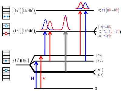
In Fig. 3 we present an example for the case in which the electrons are paired in their ground single carrier level while the holes are not. One hole is in the Oh=1 s-like orbital and the other is in the Oh=4, -like orbital. Since the electrons here are paired, they form a singlet, thus their total spin vanishes. Therefore, the e-h exchange interaction is not expected to remove the degeneracy between the holes triplet states. We find, however, that this degeneracy is slightly removed due to many-carrier mixing effects. Previous works attributed this effect to anisotropic h-h exchange interactions M. Ediger, G. Bester, A. Badolato, P. M. Petroff, K. Karrai, A. Zunger, R. J. Warburton (2007); T. Warming, E. Siebert, A. Schliwa, E. Stock, R. Zimmermann, D. Bimberg (2009), which our model does not contain.
Turning to Fig. 2 again, we note that two absorption resonances are expected from the bright exciton states into an e-singlet-h-singlet state. These two transitions form a typical cross-linearly polarized doublet, resembling the optical transitions from the vacuum to the bright exciton states (see Fig. 1). Four transitions are excepted from the exciton states into the three e-singlet-h-triplet states and four similar ones into the e-triplet-h-singlet states. Two of these four are cross-linearly polarized transitions from the bright exciton states into the state in which the two holes (or electrons) spins are anti-parallel (), and two cross-linearly polarized transitions from each one of the dark exciton states into the corresponding symmetric and anti-symmetric combinations of the parallel hole (or electron) spin states () of the biexciton. By inspecting the wavefunctions of the initial and final state of each optical transition one immediately sees that the oscillator strength of the optical transitions from the bright exciton states is exactly half that of the transitions from the dark exciton states. Moreover, since both the dark exciton and corresponding biexciton pair states are nearly degenerate, these two transitions form one unpolarized spectral line. Therefore, the total intensity of this line is four times larger than that of the other two transitions. The calculated spectra are presented in Fig. 2 and Fig. 3. In obtaining these spectra, the calculated transition energies are convoluted with normalized Gaussians of 50 width, to take into account the finite lifetime of the spin blockaded biexcitons. Transitions in which the exciton and biexciton photons are co-(cross-) linearly polarized are presented by solid- (dash-) lines, where blue- (red-) lines represent H- (V-) polarized biexciton photons.
We now turn to discuss the optical transitions into the e-triplet-h-triplet states. The electron-hole (e-h) exchange interactions, which in our QDs are typically about an order of magnitude smaller than same-carrier exchange interactions, remove the degeneracy between the states within this subgroup. We actually calculate the eigenenergies and eigenstates accurately using a CI model E. Dekel, D. Gershoni, E. Ehrenfreund, J. M. Garcia, P. M. Petroff (2000); E. Poem, J. Shemesh, I. Marderfeld, D. Galushko, N. Akopian, D. Gershoni, B. D. Gerardot, A. Badolato, P. M. Petroff (2007). However, for a more intuitive discussion one can build an effective biexciton e-h exchange Hamiltonian for the subspace of , using the single exciton effective e-h exchange Hamiltonian of Eq. 3, such that an element is defined as follows M. Z. Maialle, M. H. Degani (2007):
|
(7) |
where is the single e-h pair spin Hamiltonian for electron and hole in the orbital modes and respectively, and the subscript () denotes the initial (final) spin state. We change to a new basis in which the same-carrier exchange states are diagonal. The weak e-h exchange interactions are then treated as perturbations on these states. A similar approach was previously used for describing charged excitons (trions) K. V. Kavokin (2003); I. A. Akimov, K. V. Kavokin, A. Hundt, F. Henneberger (2005). Taking only the subspace of the e-triplet-h-triplet spin states, :
|
|
(8) |
we obtain the following matrix (neglecting many-body mixing corrections)
| (9) |
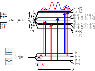
where and . In Table 1 we present the nine eigenenergies and eigenfunctions of the effective Hamiltonian . These eigenenergies and spin wavefunctions are also presented in Fig. 4. The allowed optical transitions between the ground exciton states to these biexciton states, together with their polarization selection rules, are presented as well. We note that since a photon can carry angular momentum of only, biexciton resonances of total spin 3 and 1 can be reached optically only from the ground dark exciton states. Similarly, biexciton resonances of total spin 0 and 2 can be reached optically from the bright exciton states only. Biexciton states with total spin 4 cannot be reached optically.
| Energy | Configuration |
|---|---|
| 111 is the root of the equation . The expressions in square brackets are obtained for the case . is given to order ., | |
II.3 Many-carrier mixing effects
The above discussion assumes that, to first order, the interactions between the carriers are much smaller in comparison with the single-carrier level separations. Therefore, we safely ignore contributions to the biexciton eigenstates which results from mixing with other configurations outside the subspace considered. Our model, however, does include these contributions E. Dekel, D. Gershoni, E. Ehrenfreund, J. M. Garcia, P. M. Petroff (2000); E. Poem, J. Shemesh, I. Marderfeld, D. Galushko, N. Akopian, D. Gershoni, B. D. Gerardot, A. Badolato, P. M. Petroff (2007) and as we show below, in some cases, specifically when otherwise the transitions are forbidden, mixing with other configurations are directly observed in the experimental data.
Our model includes six orbital modes for each carrier. The many-carrier eigenstates are obtained by the diagonalization of the many-body Hamiltonian, which is constructed from all the possible configurations of the confined carriers in a system of six bound levels. Thus, a many-carrier eigenstate always contains contributions from different combinations of single carriers’ orbital modes.
An example for transitions in which these contributions become important are the optical transitions from the biexciton to the first excited exciton state where the leading contribution comes from the configuration . Our model calculation resulted in optical transitions between these states, as indeed we found experimentally (see below). In Fig. 5 we describe the energy level structure of the and biexcitons. Since these excited biexciton states are spin blockaded for thermal relaxation, they decay radiatively by recombination of a ground state e-h pair. The optical transitions originated from their decay are also described in Fig. 5. If one neglects mixing, it follows that the biexcitons decay into excited excitons and the biexcitons decay into excitons. These two excited excitons are, however, highly mixed due to the Coulomb interaction between the electron and the hole. Roughly speaking, our model shows that each biexciton group decays into both excited exciton states, resulting in four sets of three spectral lines. Each group of three spectral lines resembles the sets described in Fig. 2 and Fig. 3. It contains two lower energy cross-linearly polarized lines and one, four fold stronger, unpolarized line. The calculated PL spectra which result from these transitions are presented in Fig. 5. The spectral width of the lines which results from emission to the lower energy excited exciton states [mainly ] are obtained by convoluting the calculated transitions with Gaussians of , accounting for the finite lifetime of the excited hole states. Similarly, the spectral width of the lines which result from emission to the higher energy excited exciton states [mainly ], should have been obtained by convolution with Gaussians of meV (not visible, because the convolution results in a nearly uniform, unpolarized background on the relevant energy scale), due to the much shorter lifetime of the excited electron states. The difference between the two cases is due to the difference between the relaxation rates of the hole and the electron. While a hole in the second orbital state relaxes non-radiatively to the first orbital within psec by emitting acoustical phonons E. Poem, Y. Kodriano, C. Tradonsky, B. D. Gerardot, P. M. Petroff, D. Gershoni (2010); Y. Kodriano, E. Poem, N. H. Lindner, C. Tradonsky, B. D. Gerardot, P. M. Petroff, J. E. Avron, D. Gershoni (2010), the electron does so within less than 1 psec, by coupling to optical phonons S. Hameau, Y. Guldner, O. Verzelen, R. Ferreira, G. Bastard, J. Zeman, A. Lemaître, J. M. Gérard (1999). The decay of the electrons is so rapid because the energy of optical phonons in the wetting layer, nearly resonate with the energy separation between the two electronic orbitals (29 meV Y. Benny, S. Khatsevich, Y. Kodriano, E. Poem, R. Presman, D. Galushko, P. M. Petroff, D. Gershoni (2011)).
III The experimental setup
The sample used in this work was grown by molecular-beam epitaxy on a (001) oriented GaAs substrate. One layer of strain-induced QDs was deposited in the center of a one wavelength microcavity formed by two unequal stacks of alternating quarter wavelength layers of AlAs and GaAs, respectively. The height and composition of the QDs were controlled by partially covering the InAs QDs with a 3 nm layer of GaAs and subsequent growth interruption. To improve photon collection efficiency, the microcavity was designed to have a cavity mode, which matches the QD emission due to ground state e-h pair recombinations. During the growth of the QD layer the sample was not rotated, resulting in a gradient in the density of the formed QDs. The estimated QD density in the sample areas that were measured is ; however, the density of QDs that emit in resonance with the microcavity mode is more than two orders of magnitude lower G. Ramon, U. Mizrahi, N. Akopian, S. Braitbart, D. Gershoni, T. L. Reinecke, B. Gerardot, P. M. Petroff (2006). Thus, single QDs separated apart by few tens of micrometers were easily located by scanning the sample surface during PL measurements. Strong anti-bunching in intensity auto-correlation measurements were then used to verify that the isolated QDs are single ones and that they form single photon sources.
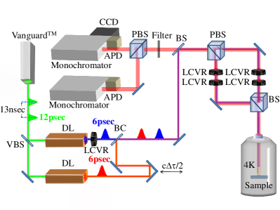
The experimental setup that we used for the optical measurements is described in Fig. 6. The sample was placed inside a sealed metal tube immersed in liquid Helium, maintaining temperature of 4.2K. A 60 microscope objective with numerical aperture of 0.85 was placed above the sample and used to focus the light beams on the sample surface and to collect the emitted PL. The majority of this work was performed with cw excitation. We used one tunable Ti:sapphire laser to scan the energy. A second Ti:sapphire laser was used for the two-photon excitation experiments. We performed also measurements with pulse excitation. In these measurements we used two dye lasers, synchronously pumped by the same frequency-doubled Nd:YVO4 (Spectra Physics-VanguardTM) laser for generating the resonantly tuned optical pulses, as described in the figure. The repetition rate of the setup was 76 MHz, corresponding to a pulse separation of about 13 nsec. The duration of the laser pulses were about 6 psec and their spectral widths about 200 . The delay between the pulses was controlled by a retroreflector on a translation stage.
The lasers emission energy could have been continuously tuned using coordinated rotations of two plate birefringent filters and a thin etalon. The polarizations of the pulses were independently adjusted using a polarized beam splitter (PBS) and two pairs of computer controlled liquid crystal variable retarders (LCVRs). The polarization of the emitted PL was analyzed by the same LCVRs and PBS. The PL was spectrally analyzed by 1-meter monochromator and detected by either a silicon avalanche photodetector or by a cooled CCD camera.
In polarized PLE spectroscopy, one monitors the polarized emission from an identified PL line while varying the energy and polarization of the exciting light source. From the variations in the intensity of the emitted PL, one can readily identify many carrier resonances in which the light is preferentially absorbed. Increased absorption, which results in increased emission intensity of a specific PL line, and its polarization sensitivity are then used to unambiguously identify the many-carrier state which forms a specific absorption resonance J. J. Finely, A. D. Ashmore, A. Lemaître, D. J. Mowbray, M. S. Skolnick, I. E. Itskevich, P. A. Maksym, M. Hopkinson, T. F. Krauss (2001); M. E. Ware, E. A. Stinaff, D. Gammon, M. F. Doty, A. S. Bracker, D. Gershoni, V. L. Korenev, S. C. Badescu, Y. Lyanda-Geller, T. L. Reinecke (2005).
IV Results
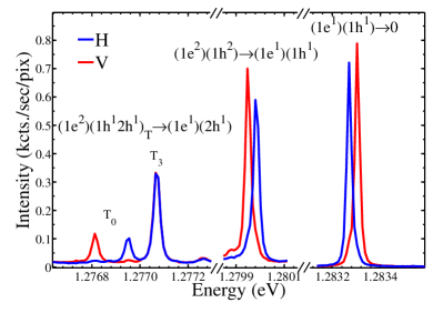
In Fig. 7 we present polarization sensitive PL spectrum of a single QD in resonance with the microcavity mode. The PL was obtained by exciting the QD with a 501 nm cw Ar+ laser. We found that at this excitation energy the QD is on average neutral Y. Kodriano, E. Poem, N. H. Lindner, C. Tradonsky, B. D. Gerardot, P. M. Petroff, J. E. Avron, D. Gershoni (2010). The excitation intensity was roughly aiming at obtaining equal emission intensity from the exciton and biexciton lines E. Dekel, D. V. Regelman, D. Gershoni, E. Ehrenfreund, W. V. Schoenfeld, P. M. Petroff (2000). The spectral neutral excitonic and biexcitonic lines, which are relevant for this study are identified above the spectral features in the figure. We note that in addition to the ground bright exciton ( to vacuum) and ground biexciton [ to ] lines, three additional biexcitonic lines are observed. These lines are due to recombination from the metastable biexciton configurations to the excited exciton eigenstates. Two cross-linearly polarized lines are due to the transitions from the biexciton configuration to the excited bright exciton eigenstates, and one, unpolarized, is due to the (almost) degenerate transitions from the biexciton configurations to the excited dark exciton configurations, . The observed emission intensity ratios of 1:1:4 is straightforward to understand Y. Kodriano, E. Poem, N. H. Lindner, C. Tradonsky, B. D. Gerardot, P. M. Petroff, J. E. Avron, D. Gershoni (2010), as discussed above.
In Fig. 8 we present PLE spectra of the neutral excitonic and biexcitonic PL lines. Each panel in the figure presents PLE spectrum of the PL spectral position marked by the vertical arrow on the expanded scale PL spectrum to the left of the panel. This set of measurements combined with additional measurements (discussed below) and the intuition that we gained from the model outlined above, allow us to resolve and identify most of the observed one- and two- photon resonances. The identified optical transitions are marked above the observed resonances.
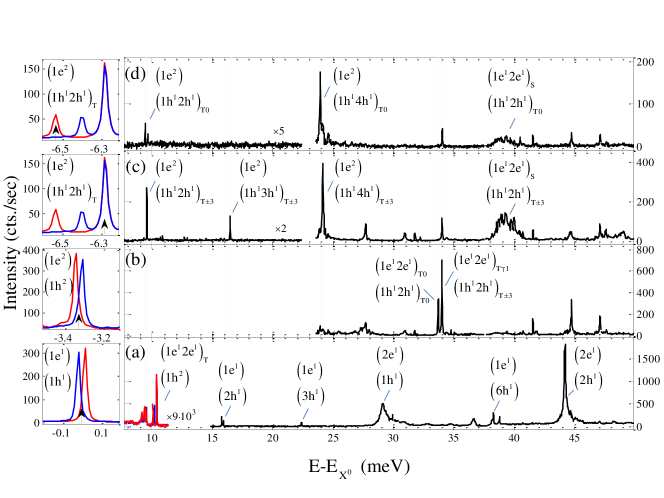
IV.1 Identification of excitonic lines
Fig. 8(a) displays single photon absorption resonances. When a photon is resonantly absorbed by the empty QD it enhances the emission from the exciton lines. The spectrum is dominated by the absorption resonance. This excitonic state in which both the electron and the heavy-hole are in their second -like orbital mode, is particularly strong due to the large overlap between the orbitals of the two carriers. The PLE spectrum contains additional, almost an order of magnitude weaker sharp resonances. These resonances are due to “non-diagonal” excitonic states, in which the electron and the heavy-hole differ in their orbital mode’s symmetry. As a result, the spatial overlap between their modes is small and the oscillator strength for the optical transition is reduced. The non-diagonal transitions that we clearly identify are the in which the electron is in its first, s-like orbital mode and the hole is in its -like modes. The oscillator strength for these transitions does not vanish, since there is some amount of overlap between the s-like and -like orbitals which are of even symmetry R. C. Miller, A. C. Gossard, G. D. Sanders, Yia-Chung Chang, J. N. Schulman (1985).
More surprising, is the observation of non-diagonal excitonic transitions between orbitals of different symmetries, like the . This transition, which is the lowest energy resonance in the exciton PLE spectrum, is unambiguously identified by its spectral position and spectral shape. As expected, it is a cross linearly polarized doublet, with the same splitting and the same energy-order of polarizations as the PL line due to the optical transition from the spin blockaded biexciton to this [] excited non-diagonal exciton states [Fig. 7]. In both cases the spectral shape is dictated by the same final exciton states. Similarly, we identified the next in energy order doublet as the non-diagonal transitions to the bright levels of the exciton. In these resonances [ and ], the electron is excited into the first, s-like, symmetric orbital mode, while the hole is excited into the second, -like, and third, -like, antisymmetric mode, respectively. These optical transitions are therefore expected to be forbidden since the orbital modes’ overlap vanishes. Their appearance indicates some symmetry breaking, possibly resulting in mixing with other bands T. Warming, E. Siebert, A. Schliwa, E. Stock, R. Zimmermann, D. Bimberg (2009); E. Siebert, T. Warming, A. Schliwa, E. Stock, M. Winkelnkemper, S. Rodt, D. Bimberg (2009).
Another important mechanism which permits these symmetry forbidden transitions is provided by phonon induced mixing. This mixing is particularly strong when the phonon energy resonates with the single carrier’s energy levels separation S. Hameau, Y. Guldner, O. Verzelen, R. Ferreira, G. Bastard, J. Zeman, A. Lemaître, J. M. Gérard (1999). Clear evidence for such type of mixing induced excitation is seen in the spectrally broad resonance 29 meV above the exciton line. This energy separation characterizes the energy of LO phonons in compounds of GaAs and InAs D. Sarkar, H. P. van der Meulen, J. M. Calleja, J. M. Meyer, R. J. Haug, K. Pierz (2005, 2008); A. Lemaître, A. D. Ashmore, J. J. Finley, D. J. Mowbray, M. S. Skolnick, M. Hopkinson, T. F. Krauss (2001); F. Findeis, A. Zrenner, G. Böhm, G. Abstreiter (2000). The optical phonon closely resonates with the 1e-2e energy levels separation, resulting in an enhanced absorption in this spectral domain. This observation is also supported by the fact that the resonance is higher in energy by about 29 meV from the resonance, as expected.
IV.2 Identification of biexcitonic lines
In Fig. 8(b-d) PLE spectra of the biexcitonic lines are presented. During these measurements one laser was tuned into the broad excitonic resonance at 29 meV, thereby populating the QD with a bright exciton. The second laser energy was then continuously varied while the emission from one of the biexciton lines was monitored.
The PLE spectrum of the ground biexciton doublet, is presented in Fig. 8(b). The allowed transitions from the bright exciton states (total spin ) into the e-triplet-h-triplet biexciton states: (total spin zero) and (total spin ) are clearly observed, dominating, as expected, this spectrum.
In Fig. 8(c) the PLE is monitored by the PL line which corresponds to the decay of the spin blockaded metastable biexciton, , by recombination of a ground e-h pair, to the excited dark exciton states, . This PLE spectrum is dominated by e-singlet-h-triplet resonances, just like the resonance from which the light is monitored. The absorption resonance transitions from the ground dark exciton directly to the monitored resonace [], by photogeneration of an Oe=1 Oh=2 e-h pair, is clearly identified as the lowest energy resonance in this PLE spectrum. Likewise, the resonances in which the hole is excited into the Oh=3 and Oh=4 orbitals, [ and , respectively] are clearly identified as well. Photogenerated holes in these resonances nonradiatively relax to the Oh=2 level, where recombination occurs, since further non-radiative relaxation is spin blockaded E. Poem, Y. Kodriano, C. Tradonsky, B. D. Gerardot, P. M. Petroff, D. Gershoni (2010); Y. Kodriano, E. Poem, N. H. Lindner, C. Tradonsky, B. D. Gerardot, P. M. Petroff, J. E. Avron, D. Gershoni (2010).
In addition, a broad resonance is observed 29 meV above the biexciton resonance. This resonance is due to absorption into the . This state is strongly coupled to the , by a one LO phonon, in a similar way to the coupling between the and the bright exciton states [Fig. 8(a)].
Similar spectral features are observed in Fig. 8(d) where the PLE is monitored through the decay of the metastable biexciton to the excited bright exciton state . In this spectrum the absorption resonances from the bright exciton states to the and the states are identified. The weaker resonant absorption into the state, is missing from this spectrum due to poor signal to noise ratio.
We note that the energy difference between the optical transitions and , is 15.7 meV. As expected, this difference exactly matches the energy of the optical transition from the vacuum into the first excited exciton state .
The transitions to the states which are clearly observed in Fig. 8(c) and (d), are absent from the PLE spectrum of the ground biexciton [Fig. 8(b)]. This is due to the fact that in these cases the emitting state is directly excited and no intermediate non-radiative relaxation process is required. This is not the case when the state is excited. Here, since non-radiative relaxation of the hole must occur prior to the recombination, the resonance is weakly observed in the PLE spectrum of the ground biexciton state, as well. This means that in the relaxation process of the hole from the Oh=4 to the Oh=2 orbital state, its spin may slightly scatter E. Poem, Y. Kodriano, C. Tradonsky, B. D. Gerardot, P. M. Petroff, D. Gershoni (2010). Last, we note that the resonances and which are due to optical transitions from the bright exciton states are only observed in the PLE spectrum of the ground biexciton state [Fig. 8(b)]. Similarly, the resonances and , which are due to optical transitions from the dark exciton states are only observed in PLE spectra of the spin blockaded biexcitons [Fig. 8(c) and (d)]. We note however, that the bright exciton resonances spectrally overlap with the dark exciton resonances and , and therefore their final identification is also based on polarization sensitive and time resolved spectroscopy as explained below.
In Fig. 9, we present examples for the use of polarization sensitive spectroscopy as a tool for verifying the identity of the observed spectral resonances. The PLE resonances as monitored by the four biexcitonic PL transitions and by the ground exciton state, are displayed in the figure for various combinations of rectilinear polarizations of the exciting two lasers and the detected PL. Since the figure describes e-singlet-h-triplet resonances, the experimentally measured optical transitions and their polarization selection rules can be directly compared with the theoretical expectations outlined in Fig. 3. The characteristic three lines structure of the optical transition into the e-singlet-h-triplet state is clearly resolved in Fig. 9. The lowest energy biexcitonic doublet is crossed linearly polarized, since each component is due to excitation of a different bright exciton eigenstate. The high energy line is unpolarized, and its intensity is twice stronger, (even in rectilinear polarization) since it gets contributions from the two optically allowed transitions of the dark exciton eigenstates E. Poem, Y. Kodriano, C. Tradonsky, N. H. Lindner, B. D. Gerardot, P. M. Petroff, D. Gershoni (2010). We note in particular, that the energy separation between the cross-linearly polarized components of the lower energy doublet, exactly matches, as expected, that of the bright exciton (-34 ). The two lasers PLE spectrum of the ground state exciton [Fig. 9(c)] reveals a striking difference between transitions from the bright exciton states and transitions from the dark ones. In The first type of transitions population from the bright exciton is transferred into the biexciton state, in which polarization memory is totally lost, and thus the polarized PL emission is reduced. In the latter type population is transferred from the dark exciton into the bright exciton state due to the rxcitation to the biexciton state. Therefore, in this case the PL emission from the bright exciton states is enhanced.
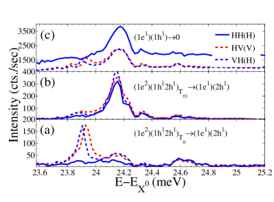
In Fig. 10, we use similar methods for studying the richer spectrum of the e-triplet - h-triplet resonances. In this figure the optical transitions into the biexciton states are studied and the experimentally measured transitions should be compared with the theoretical considerations outlined in Fig. 4. As can be seen in Fig. 4, there are six optical transitions from the bright exciton states into the e-triplet - h-triplet states, and four optical transitions from the dark exciton states. The lowest energy transitions are the cross-linearly polarized doublet due to optical transitions from the bright exciton states into the biexciton. As mentioned above, this biexciton resonance is only observed in the PL from the ground biexciton states. For these optical transitions to occur, both lasers should be co-linearly polarized, as indeed the data show [Fig. 10(a)]. In addition there is a higher energy doublet due to the four optical transitions from the bright exciton states into the symmetric and anti-symmetric biexciton states of total spin projection 2. Since these biexciton states are almost degenerate (in a similar way to the dark exciton states), the four transitions form an unpolarized doublet which is twice as strong as the lower energy cross-polarized one. Again, this is exactly what one sees in the polarization sensitive PLE spectrum of the ground biexciton [Fig. 10(a)].
In Fig. 10(b) a strong resonance in the PLE spectrum of the PL line to is observed. The resonances in this spectrum are expected to result mainly from excitations of the dark exciton states. As seen in see Fig. 4, the optical transitions from the dark exciton states are expected to form a cross linearly polarized doublet. Unfortunately, this doublet spectrally overlaps the unpolarized doublet due to transitions from the bright exciton states. We use time resolved pulsed PLE spectroscopy in order to resolve these transitions.
In Fig. 10(c) we show two-pulse polarization sensitive PLE spectra of the bright exciton lines when the temporal separation between the two pulses is relatively short (30 psec), while in Fig. 10(d) these spectra are shown for the case in which the temporal separation is 13 nsec. While in the first case, immediately after the photogeneration the exciton population is bright, in the second case only dark exciton population lasts. The PLE spectroscopy reveals this fact in the following way: When the second pulse is tuned into a bright exciton to biexciton transition, the PL signal from the exciton lines is reduced, since from the biexciton state part of the population does not return to the monitored exciton state. This is particularly true for co-polarized pulses, since the polarization memory is lost in the biexciton states. Therefore, bright exciton transitions are seen as dips in the PLE spectrum of the exciton for co-polarized pulses and as peaks for cross-polarized pulses. Dark exciton transitions are always obtained as peaks in the PLE spectrum of the exciton, since they transfer dark population into bright one through the biexciton states. Thus, the polarized nature of the optical transitions from the dark exciton states into the biexciton states are clearly revealed in the polarization sensitive PLE spectra of the exciton in Fig. 10(d).
IV.3 The non-diagonal optical transitions
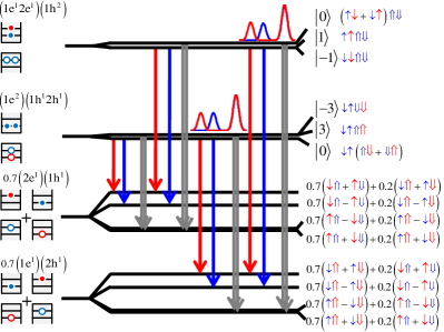
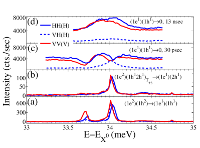
In Fig. 11 we focus our attention on the “non-diagonal” optical transitions that we identified in the PL and the one and two color PLE spectra. Only transitions which include -like orbitals are considered. Fig. 11(a) schematically describes the relevant excitonic and biexcitonic energy levels and the optical transitions between them, once the non-diagonal transitions become allowed. The (un-normalized) spin wavefunctions are described to the left of each level. Downward (upward) vertical arrow describes emission (absorption) and blue (red) stands for H (V) polarization. Gray arrows describe unpolarized transitions. We note that the transitions between the biexciton states and the exciton states are observed both in PL and in PLE spectra.
The spectra are characterized by two repeating patterns: The first one is a cross-linearly polarized doublet. This doublet is due to the anisotropic e-h exchange induced splitting of the bright exciton states. In these doublets the symmetric state is lower (higher) in energy than the antisymmetric state for diagonal (non-diagonal) optical transitions. The second pattern has three spectral lines: a higher energy unpolarized line and a lower energy cross-linearly polarized doublet. This pattern is due to transitions from exciton to biexciton singlet-triplet states. The doublet is due to transitions from the bright exciton states and the unpolarized line is due to transitions from the dark exciton states. The optical transitions which are schematically described in Fig. 11(a) are linked to the experimentally measured transitions in the PL and in the PLE spectra [Fig. 11(b)].
| Energy separation | Measured value [] |
|---|---|
| 123 | |
| -34 | |
| 200 | |
| 151 | |
| 60 | |
| 222extracted from the doublet and from the e-triplet-h-triplet resonances. (see Fig. 4). | 60 |
Our ability to unambiguously identify all these non-diagonal optical transitions allows us to fully characterize the QD in terms of single carriers’ orbital mode energies and various interaction terms between carrier pairs. The energies extracted from our spectroscopy are summarized in Table 2.
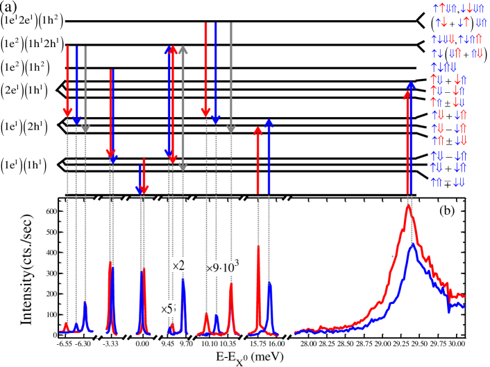
In Fig. 12 we compare between the measured excitonic and biexcitonic optical transitions and the calculated ones. Good agreement is achieved using the QD parameters listed in Table 3. One notes that transitions which include the second single electron state 2e, deviate the most from the calculated ones. We believe that it is due to the optical phonon induced coupling between this state and the first electronic state. Our model does not consider this coupling.
Finally, we note that the three optical transitions from the to the states are observed in the measured PL spectrum. This confirms our many-body description, as discussed in section II.3.
| Parameter | Value |
|---|---|
| 111Reference E. Poem, J. Shemesh, I. Marderfeld, D. Galushko, N. Akopian, D. Gershoni, B. D. Gerardot, A. Badolato, P. M. Petroff (2007). | 0.25 |
| 11footnotemark: 1 | 0.065 |
| 53Å | |
| 74Å | |
| 0.87 |
V Summary
In summary, we presented a comprehensive study of single, neutral semiconductor quantum dots subject to excitation by two variably polarized resonant excitations, one to exciton resonances, and the other to biexciton resonances. By monitoring the emission intensity from various exciton and biexciton lines we completely characterize the rich one- and two-photon absorption spectra of single semiconductor quantum dots. The measured data is compared with a many carrier theoretical model, based on simple, one band parabolic potentials for electrons and heavy-holes. While the model provides full understanding of the observed resonances, in terms of line shapes, energies and polarization selection rules, it is short of quantitatively describing intensities of various “non-diagonal” optical transitions and spectral features which involve strong coupling with optical phonons. We believe that the understanding that our study provides, should be very useful in applying semiconductor quantum dots as devices for quantum logical gates.
Acknowledgements.
The support of the US-Israel binational science foundation (BSF), the Israeli science foundation (ISF), the ministry of science and technology (MOST), Eranet Nano Science Consortium and that of the Technion’s RBNI are gratefully acknowledged. We also acknowledge helpful discussions with Dr. Garnett Bryant.References
- M. Ediger, G. Bester, A. Badolato, P. M. Petroff, K. Karrai, A. Zunger, R. J. Warburton (2007) M. Ediger, G. Bester, A. Badolato, P. M. Petroff, K. Karrai, A. Zunger, R. J. Warburton, Nature Physics 3, 774 (2007).
- E. Poem, J. Shemesh, I. Marderfeld, D. Galushko, N. Akopian, D. Gershoni, B. D. Gerardot, A. Badolato, P. M. Petroff (2007) E. Poem, J. Shemesh, I. Marderfeld, D. Galushko, N. Akopian, D. Gershoni, B. D. Gerardot, A. Badolato, P. M. Petroff, Phys. Rev. B 76, 235304 (2007).
- P. Michler, A. Kiraz, C. Becher, W. V. Schoenfeld, P. M. Petroff, L. Zhang, E. Hu, A Imamoglu (2000) P. Michler, A. Kiraz, C. Becher, W. V. Schoenfeld, P. M. Petroff, L. Zhang, E. Hu, A Imamoglu, Science 290, 2282 (2000).
- P. Zanardi, F. Rossi (1998) P. Zanardi, F. Rossi, Phys. Rev. Lett. 81 (1998).
- A. Imamoḡlu, D. D. Awschalom, G. Burkard, D. P. DiVincenzo, D. Loss, M. Sherwin, A. Small (1999) A. Imamoḡlu, D. D. Awschalom, G. Burkard, D. P. DiVincenzo, D. Loss, M. Sherwin, A. Small, Phys. Rev. Lett. 83, 4204 (1999).
- D. Press, K. De Greve, P. L. McMahon, T. D. Ladd, B. Friess, C. Schneider, M. Kamp, S. H¨fling, A. Forchel, Y. Yamamoto (2010) D. Press, K. De Greve, P. L. McMahon, T. D. Ladd, B. Friess, C. Schneider, M. Kamp, S. H¨fling, A. Forchel, Y. Yamamoto, Nature Photonics 4 (2010).
- H. Kosaka, T. Inagaki, Y. Rikitake, H. Imamura, Y. Mitsumori, K. Edamatsu1 (2009) H. Kosaka, T. Inagaki, Y. Rikitake, H. Imamura, Y. Mitsumori, K. Edamatsu1, Nature 457 (2009).
- Y. Benny, S. Khatsevich, Y. Kodriano, E. Poem, R. Presman, D. Galushko, P. M. Petroff, D. Gershoni (2011) Y. Benny, S. Khatsevich, Y. Kodriano, E. Poem, R. Presman, D. Galushko, P. M. Petroff, D. Gershoni, Phys. Rev. Lett. 106 (2011).
- D. P. DiVincenzo (1995) D. P. DiVincenzo, Science 270, 255 (1995).
- R. Singh, G. Bester (2010) R. Singh, G. Bester, Phys. Rev. Lett. 104, 196803 (2010).
- R. J. Warburton, B. T. Miller, C. S. Dürr, C. Bödefeld, K. Karrai, J. P. Kotthaus, G. Medeiros-Ribeiro, P. M. Petroff, S. Huant (1998) R. J. Warburton, B. T. Miller, C. S. Dürr, C. Bödefeld, K. Karrai, J. P. Kotthaus, G. Medeiros-Ribeiro, P. M. Petroff, S. Huant, Phys. Rev. B 58, 16221 (1998).
- A. Barenco, M. A. Dupertuis (1995) A. Barenco, M. A. Dupertuis , Phys. Rev. B 52, 2766 (1995).
- E. Dekel, D. Gershoni, E. Ehrenfreund, J. M. Garcia, P. M. Petroff (2000) E. Dekel, D. Gershoni, E. Ehrenfreund, J. M. Garcia, P. M. Petroff, Phys. Rev. B 61, 11009 (2000).
- M. Bayer, G. Ortner, O. Stern, A. Kuther, A. A. Gorbunov, A. Forchel, P. Hawrylak, S. Fafard, K. Hinzer, T. L. Reinecke, S. N. Walck, J. P. Reithmaier, F. Klopf, F. Schäfer (2002) M. Bayer, G. Ortner, O. Stern, A. Kuther, A. A. Gorbunov, A. Forchel, P. Hawrylak, S. Fafard, K. Hinzer, T. L. Reinecke, S. N. Walck, J. P. Reithmaier, F. Klopf, F. Schäfer, Phys. Rev. B 65, 195315 (2002).
- T. Takagahara (2000) T. Takagahara, Phys. Rev. B 62, 16840 (2000).
- E. L. Ivchenko, G. E. Pikus (1997) E. L. Ivchenko, G. E. Pikus, Superlattices and other Heterostructures (Springer-Verlag, Berlin, 1997).
- E. Poem, Y. Kodriano, C. Tradonsky, N. H. Lindner, B. D. Gerardot, P. M. Petroff, D. Gershoni (2010) E. Poem, Y. Kodriano, C. Tradonsky, N. H. Lindner, B. D. Gerardot, P. M. Petroff, D. Gershoni, Nature Physics 6, 993 (2010).
- S. Alon-Braitbart, E. Poem, L. Fradkin, N. Akopian, S. Vilan, E. Lifshitz, E. Ehrenfreund, D. Gershoni, B. D. Gerardot, A. Badolato, P. M. Petroff (2006) S. Alon-Braitbart, E. Poem, L. Fradkin, N. Akopian, S. Vilan, E. Lifshitz, E. Ehrenfreund, D. Gershoni, B. D. Gerardot, A. Badolato, P. M. Petroff, Physica E 32, 127 (2006).
- D. Gammon, E. S. Snow, B. V. Shanabrook, D. S. Katzer, D. Park (1996) D. Gammon, E. S. Snow, B. V. Shanabrook, D. S. Katzer, D. Park , Phys. Rev. Lett. 76, 3005 (1996).
- E. Poem, Y. Kodriano, C. Tradonsky, B. D. Gerardot, P. M. Petroff, D. Gershoni (2010) E. Poem, Y. Kodriano, C. Tradonsky, B. D. Gerardot, P. M. Petroff, D. Gershoni, Phys. Rev. B 81, 085306 (2010).
- Y. Kodriano, E. Poem, N. H. Lindner, C. Tradonsky, B. D. Gerardot, P. M. Petroff, J. E. Avron, D. Gershoni (2010) Y. Kodriano, E. Poem, N. H. Lindner, C. Tradonsky, B. D. Gerardot, P. M. Petroff, J. E. Avron, D. Gershoni, Phys. Rev. B 82 (2010).
- G. Bastard (1990) G. Bastard, wave mechanics applied to semiconductors heterostructures (Les Edition de Physique, Paris, 1990).
- R. C. Miller, A. C. Gossard, G. D. Sanders, Yia-Chung Chang, J. N. Schulman (1985) R. C. Miller, A. C. Gossard, G. D. Sanders, Yia-Chung Chang, J. N. Schulman , Phys. Rev. B 32, 8452 (1985).
- T. Warming, E. Siebert, A. Schliwa, E. Stock, R. Zimmermann, D. Bimberg (2009) T. Warming, E. Siebert, A. Schliwa, E. Stock, R. Zimmermann, D. Bimberg, Phys. Rev. B 79 (2009).
- E. Siebert, T. Warming, A. Schliwa, E. Stock, M. Winkelnkemper, S. Rodt, D. Bimberg (2009) E. Siebert, T. Warming, A. Schliwa, E. Stock, M. Winkelnkemper, S. Rodt, D. Bimberg, Phys. Rev. B 79 (2009).
- M. Z. Maialle, M. H. Degani (2007) M. Z. Maialle, M. H. Degani, Phys. Rev. B 76, 115302 (2007).
- K. V. Kavokin (2003) K. V. Kavokin, Phys. Stat. Sol. 195, 06157 (2003).
- I. A. Akimov, K. V. Kavokin, A. Hundt, F. Henneberger (2005) I. A. Akimov, K. V. Kavokin, A. Hundt, F. Henneberger, Phys. Rev. B. 71, 075326 (2005).
- S. Hameau, Y. Guldner, O. Verzelen, R. Ferreira, G. Bastard, J. Zeman, A. Lemaître, J. M. Gérard (1999) S. Hameau, Y. Guldner, O. Verzelen, R. Ferreira, G. Bastard, J. Zeman, A. Lemaître, J. M. Gérard, Phys. Rev. B 83, 4152 (1999).
- G. Ramon, U. Mizrahi, N. Akopian, S. Braitbart, D. Gershoni, T. L. Reinecke, B. Gerardot, P. M. Petroff (2006) G. Ramon, U. Mizrahi, N. Akopian, S. Braitbart, D. Gershoni, T. L. Reinecke, B. Gerardot, P. M. Petroff Phys. Rev. B 73, 205330 (2006).
- J. J. Finely, A. D. Ashmore, A. Lemaître, D. J. Mowbray, M. S. Skolnick, I. E. Itskevich, P. A. Maksym, M. Hopkinson, T. F. Krauss (2001) J. J. Finely, A. D. Ashmore, A. Lemaître, D. J. Mowbray, M. S. Skolnick, I. E. Itskevich, P. A. Maksym, M. Hopkinson, T. F. Krauss, Phys. Rev. Lett. 63, 073307 (2001).
- M. E. Ware, E. A. Stinaff, D. Gammon, M. F. Doty, A. S. Bracker, D. Gershoni, V. L. Korenev, S. C. Badescu, Y. Lyanda-Geller, T. L. Reinecke (2005) M. E. Ware, E. A. Stinaff, D. Gammon, M. F. Doty, A. S. Bracker, D. Gershoni, V. L. Korenev, S. C. Badescu, Y. Lyanda-Geller, T. L. Reinecke, Phys. Rev. Lett. 95, 177403 (2005).
- E. Dekel, D. V. Regelman, D. Gershoni, E. Ehrenfreund, W. V. Schoenfeld, P. M. Petroff (2000) E. Dekel, D. V. Regelman, D. Gershoni, E. Ehrenfreund, W. V. Schoenfeld, P. M. Petroff, Phys. Rev. B 62 (2000).
- D. Sarkar, H. P. van der Meulen, J. M. Calleja, J. M. Meyer, R. J. Haug, K. Pierz (2005) D. Sarkar, H. P. van der Meulen, J. M. Calleja, J. M. Meyer, R. J. Haug, K. Pierz, Phys. Rev. B 71, 081302 (2005).
- D. Sarkar, H. P. van der Meulen, J. M. Calleja, J. M. Meyer, R. J. Haug, K. Pierz (2008) D. Sarkar, H. P. van der Meulen, J. M. Calleja, J. M. Meyer, R. J. Haug, K. Pierz, Appl. Phys. Lett. 92, 181909 (2008).
- A. Lemaître, A. D. Ashmore, J. J. Finley, D. J. Mowbray, M. S. Skolnick, M. Hopkinson, T. F. Krauss (2001) A. Lemaître, A. D. Ashmore, J. J. Finley, D. J. Mowbray, M. S. Skolnick, M. Hopkinson, T. F. Krauss, Phys. Rev. B 63, 161309 (2001).
- F. Findeis, A. Zrenner, G. Böhm, G. Abstreiter (2000) F. Findeis, A. Zrenner, G. Böhm, G. Abstreiter, Phys. Rev. B 61, R10579 (2000).