Interlayer repulsion and decoupling effects in stacked turbostratic graphene flakes
Abstract
The behavior of stacked graphene flakes is found to be governed by the strength of the repulsive interactions that arise due to the orthogonality of interlayer orbitals. Therefore, the decoupling effect in AA stacked layers is a result of the repulsion being dominant over the orbital interactions while misorientation of 2∘-5∘ is an attempt by the system to suppress that repulsion. For misorientated graphene, in the regions of superposed lattices in the Moiré pattern, the repulsion between the layers manifest itself as lattice distortion by forming a bump.
Ever since the discovery of graphene obtained by mechanical exfoliation of graphite nov , the enormous interest on this material that exhibits many unique electronic properties is yet to subside review . However, the focus has recently shifted to the epitaxial growth of graphene varchon ; naturep ; hass as being a more advanced process to control the graphene geometry that would be beneficial for its application in electronics. Here, the multilayer structures are of particular interest due to their high robustness and because their electronic properties can be manipulated through variation of the number and orientation of the layers hass ; naturep ; varchon . A clear understanding of the influence of the layer orientation on the electronic properties of graphene is one of the most urgent issues that need to be resolved. It was observed by several groups that the AA stacked epitaxial systems experience a misorientation of 2∘-5∘ hass ; naturep ; varchon between the layers and exhibit the electronic properties of a monolayer graphene because of decoupling of the layers, which also occurs in graphene obtained by chemical vapor deposition reina and ultrasonicating graphite warner . The decoupling is also observed for another commensurate angle near 30∘ hass . This behavior is different from that known for the AB stacked bilayer graphene mccann ; latil . Several theoretical works were reported on the electronic properties of twisted graphene latil ; shall ; lopes and indeed the monolayer behavior for has been confirmed. However, no proper explanation of the underlying physical reasons for the electronic decoupling is available as yet.
The carbon atoms in graphene are connected by the covalent bonds in hybridization. After forming the hexagonal lattice, each carbon atom has one extra valence electron residing on the orbital. Those - electrons generate the and bands which meet and display linear dispersion in the vicinity of the K-points review . As the orbitals are orthogonal to the graphene plane, in a system of two stacked layers the orbitals interact. When the lattices of the two layers are superposed, the conditions for a perfect overlap of the orbitals are created. However, decoupling between the layers as seen in the experiments requires an opposite behavior which inspired us to investigate this phenomena in the present work with the help of the quantum chemistry methods nbo . In graphene the electrons completely fill the bonding orbitals thereby generating a closed electron shell. When two closed-shell systems are stacked, the interlayer interaction of their orbitals is repulsive. The bonding and antibonding interactions which may be different from zero individually, will overall cancel each other and the electrons are expelled from the overlap region.
The interlayer coupling is the parameter most widely used in the tight-binding approximation, which is why we intend to investigate how the coupling is influenced by the repulsion. We considered two graphene flakes (Fig. 1 (a)) with non-linear edges terminated by hydrogen atoms thereby excluding the appearance of localized states which would closely resemble the infinite case. To estimate the interlayer coupling we employ the natural bond orbital (NBO) analysis nbo . This method uses the electron density distribution obtained after the DFT calculation (with the UB3LYP/6-31+G* hybrid exchange-correlation functional) to build the natural bond orbitals . The interaction matrix required to perturb the natural bond orbitals and into the molecular orbitals is then created for all the double bonds involved in the interaction between two molecular fragments. Each element is for the electronic coupling between the bonds, while the sum of defines the interlayer coupling between the two flakes. Within the NBO procedure the Pauli exclusion principle is applied to the outer and inner nodes thereby preserving the interatomic orthogonality and its for electrons on the same orbital. That is an important advantage of using the NBO for closed-shell systems like graphene. The occupancy charge transfer from one flake to another is then calculated as the sum of transfers between the donor and acceptor orbitals, where are the orbital energies. The transfer is calculated for the stabilizing interactions, i.e. when the second-order interaction energy is positive.
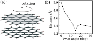
The orthogonality of the orbitals when the two layers are superposed can be destroyed by a rotation of the flake as shown in Fig. 1 (a). Increasing the twist angle from to 30∘ we calculate the occupancy transfers between the layers () and the off-diagonal element for an interlayer distance of 3.34 Å (typical for graphite). The results are collected in Table 1. To estimate the interlayer coupling we took an average magnitude of the interaction matrix defined as for every interaction between the bonds and divided by the number of double bonds in one layer.
| , ∘ | (), ē | ||||
|---|---|---|---|---|---|
| 0.0 | 0.0018 (0.0019) | 0.03 | -3.94 (0.835) | 1.32 | 0.0 (0.0) |
| 1.5 | 0.0029 (0.0027) | 0.04 | -3.95 (0.812) | 1.33 | -0.02 (-0.02) |
| 3.0 | 0.0038 (0.0035) | 0.05 | -3.96 (0.765) | 1.35 | -0.06 (-0.06) |
| 6.0 | 0.0064 (0.0057) | 0.11 | -4.02 (0.638) | 1.45 | -0.19 (-0.21) |
| 9.0 | 0.0110 (0.0098) | 0.18 | -4.09 (0.476) | 1.60 | -0.36 (-0.43) |
| 12.0 | 0.0152 (0.0129) | 0.22 | -4.19 (0.294) | 1.79 | -0.46 (-0.65) |
| 15.0 | 0.0171 (0.0157) | 0.24 | -4.34 (0.012) | 1.99 | -0.63 (-0.83) |
| 18.0 | 0.0184 (0.0156) | 0.24 | -4.31 (0.077) | 1.92 | -0.66 (-0.93) |
| 21.0 | 0.0179 (0.0159) | 0.25 | -4.24 (0.245) | 1.78 | -0.70 (-0.99) |
| 26.0 | 0.0141 (0.0136) | 0.23 | -4.15 (0.459) | 1.64 | -0.67 (-0.96) |
| 30.0 | 0.0140 (0.0148) | 0.21 | -4.13 (0.510) | 1.65 | -0.64 (-0.88) |
| AB | 0.0177 (0.0181) | 0.24 | -4.35 (0.108) | 2.01 | -0.86 (-1.31) |
For the 0∘ twist angle the extremely weak interlayer interaction occurs mainly between the double bonds located on top of each other such that the stacked orbitals are orthogonal. These interactions are found to cancel when the graphene lattice is relaxed within the graphene plane. The interaction for other combination of double carbon bonds (the next-nearest neighbor interlayer interactions) is also almost zero because of their remoteness from each other. Therefore for the interlayer coupling and the occupancy transfer are close to zero ( is compensated by within the intermolecular threshold of 0.0013 eV nbo ).
The flake rotation leads to the suppression of repulsion between the layers and a manifestation of the next-nearest neighbor interlayer interactions thus enhancing the interlayer coupling. The effect of vanishing repulsion is reflected by an increase of the electron density in the overlap region (the forces expelling the electrons from the overlap region are reduced). This leads to an enhancement of the occupancy transfer along with the interaction matrix . Thus, for those orbitals that are orthogonal at , the increases from 0.22 eV (at ) to 0.25 eV. For the Bernal stacking (AB) the repulsion between layers reaches a minimum and together with the high orbital overlap (many of the double bonds belonging to the different layers are aligned thus leading to a large overlap) one generates the highest occupancy charge transfer between the graphene layers (AB in Table 1). Therefore, for AB stacking the value of is increased up to 0.30 eV for the nearest interlayer interactions, while for the next nearest neighbor interactions it varies in the range of 0.08-0.16 eV. These results are consistent with the experimental data for AB stacking malard . Because with rotation an increase of is not significant for those orbitals which have been orthogonal at , an enhancement of the occupancy transfer occurs mostly due to the development of the next-nearest neighbor interlayer interactions.
Therefore, for an increase in the occupancy transfer reaches its maximum as the orbital overlap is still significant but the repulsion is already weak (interlayer location of the double bonds is somewhat parallel thereby providing the efficient overlap). Moreover, at this angle one layer clearly becomes a donor while the other is an acceptor such that . For the charge transfer starts to diminish because the interacting orbitals are becoming distant and misoriented from being parallel thereby suppressing their overlap. Misorientation is large for both the nearest and next-nearest neighbor interactions, and at the misorientation reaches its maximum. Our results also reveal that for the significant misorientation of the interlayer separated orbitals would induce a relocation of the double bonds to new positions such that the occupancy transfer not only diminishes but also becomes equal in both directions . Therefore, the twist angles /6 ( is the positive integral number) are the critical points for which the reduction of interlayer coupling is induced by the suppression of the orbital overlap and by initiation of relocation of the double bonds. The twist angles are another specific points for which the interlayer coupling is suppressed to almost zero because of the significant repulsion between the layers as the interlayer orbitals become again orthogonal. The same effect occurs for the angles 2/3 if the rotation axis is located at the center of the carbon ring.
If the conformation changes are not allowed in the system where the repulsive interactions dominate, an increase in energy for pairs of interacting electrons occurs and one should consider the alteration of their orbital energies for both occupied and unoccupied orbitals (HOMO and LUMO) and the total energy (). The important proof of the presence of a repulsion between the stacked flakes is the appearance of destabilization as the flakes move closer because then the repulsion is significantly enhanced. Thus, with a reduction of the interlayer distance from 3.34 Å to 2.5 Å the total energy is enhanced by 22.35 eV. Moreover, this leads to a reduction of by half for orthogonal interactions. The total energy additionally deviates with layer rotation being a function of the orbital mixing altered by the rotation (see in Table 1). To account for the contribution of the van der Waals interactions we applied the local Møller-Plesset second order perturbation theory (local MP2/6-31+G*) which provided some reduction in the .
The interaction of the stacked graphene layers initiates the perturbation of their orbitals thereby modifying the orbital energies that are identical in the two layers before perturbation. This shift can be estimated as
where and are the molecular -orbital energies before (for identical graphene flakes ) and after perturbation, respectively. is the orbital overlap. is the intrinsic interaction integral considering the contribution from the electron-electron interactions and particularly of its repulsive part to the orbital energies . The orbital energies and splitting of HOMO orbitals with rotation are presented in the Table 1.
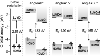
In Fig. 2 we show the energy diagram for alteration of the HOMO and LUMO orbitals due to stacking of graphene layers with the twist angles 0∘, 15∘ and 30∘, which we argued above as points of particular interest. For a graphene flake of such a small size (11.49.8 Å) the HOMO-LUMO gap is quite large that is due to the strong confinement effect son-ritter , while hydrogenation of the edges is a factor enlarging the gap even further barone . For zero twist angle the interlayer located orbitals are perfectly orthogonal. However, the valence electrons are expelled from the overlap region by the repulsive forces that suggest their zero overlap (=0). Therefore, contribution of the term into the orbital energies vanishes. This suggests almost no orbital mixing, so that the splitting of two HOMO orbitals () is defined by the repulsive part of the electron-electron interactions () and reaches its maximum (=0.835 eV). Our simulation results shown in Fig. 2 reveal that for the large splitting of the (HOMO-(HOMO-1)) and ((LUMO+1)-LUMO) initiates the moving of HOMO and LUMO orbitals closer to each other thereby reducing the HOMO-LUMO gap to =1.33 eV. However, the gap attributed to each layer HOMO-(LUMO+1) and (HOMO-1)-LUMO is being similar to that before perturbation.
The rotation of the flakes breaks the orthogonality of orbitals thereby inducing the non-zero overlap such that the contribution of the term to orbital energies is non-zero. For the twist angle the combination of a large orbital overlap and low repulsion leads to almost zero splitting of the (HOMO-(HOMO-1)) thereby increasing the HOMO-LUMO gap to 1.99 eV. For the twist angle the interlayer orbitals become significantly distant and misorientated from their parallel alignment thus suppressing the orbital overlap . However, the contribution of the repulsion part to the interaction integral is much lower than that for and therefore, an enhancement of the splitting due to suppression of is insignificant in comparison to that for the zero angle. As a result the size of the HOMO-LUMO gap is reduced only to =1.65 eV that is much smaller than for , but larger than for . For AB stacking the HOMO-LUMO gap reaches its maximum because of the combination of the large orbital mixing and low orbital repulsion (=2.01 eV).
Strong repulsion arising between stacked graphene flakes tend to increase the interlayer separation up to an equilibrium point when the attraction between the layers cancel the effect of repulsion. To simulate this behavior we relaxed the system allowing the conformation changes only in the direction orthogonal to the graphene plane (full relaxation of the structure leads to sliding of the flakes away from each other). The equilibrium distance is found to deviate with the twist angle. For the AB stacked flakes for which the repulsion is found to be the weakest, the equilibrium distance is 4.21 Å, while when the two lattices are superposed in AA stacking this distance approaches its maximum 4.99 Å. Therefore, as the increase in the twist angle between the flakes induces suppression of the interlayer repulsion, the equilibrium interlayer distance is reduced as shown in Fig. 1 (b). The discrepancy of the magnitude of the interlayer distance calculated for small flakes (11.49.8 Å) from that of the standard value 3.4 Å for the stacked graphene layers, occurs due to the finite size effects and insufficient representation of the non-local dispersive interactions in the DFT techniques lebedev . In the case when the flakes are separated by the equilibrium distance depicted in Fig. 1 (b), the electronic properties resemble those for stacking such that the HOMO-LUMO gap ( 2.0 eV) remains almost unchanged for all values of the twist angles and so is the total energy of the system (). The splitting of the (HOMO-(HOMO-1)) is insignificant (0.051 eV) thereby suggesting the efficient charge exchange between the two layers. Extrapolation of these results to the graphene layers of infinite size may lead to an important (and unique) situation which is described below.
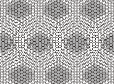
The misorientation of stacked graphene layers observed experimentally hass ; naturep ; varchon ; reina ; warner leads to the appearance of the Moiré pattern as shown in Fig. 3. In this pattern, some areas (spots shaded in Fig. 3) reveal the superposition of the graphene lattices (AA stacking), while in the inter-spot region the stacking similar to AB type is found to prevalent. The strong interlayer repulsion appearing in the areas of AA stacking tend to move the lattices apart, while in the rest of the system the prevalence of AB stacking tend to keep the graphene layers together. Therefore, in the areas of superposed lattice the repulsion would induce geometrical distortions in the form of bumps formed on the graphene surface. The diameter of each bump and its height (the bigger the spot size the weaker the elastic stress at the bump’s boundaries) would be reduced with growing rotation angle. To confirm this statement we applied the geometry optimization (allowing the lattice relaxation in the direction orthogonal to the graphene plane) to the stacked graphene flakes of size 17.515.8 Å for which the superposed and AB stacking areas are well defined for the rotation angle of 10∘. Indeed, the formation of the bumps of height 0.20Å was obtained on each flake. However, in the misoriented graphene layers we expect the bumps to be higher due to the smaller rotation angle and larger areas of inter-spot regions possessing the AB stacking where the repulsion will be weaker than in our model system. The suppression of the repulsion between the layers due to the lattice distortion makes the band structure uniform over the whole system.
In summary, two graphene layers stacked with a twist angle approaching
display the electronic properties of a decoupled system because of the strong
interlayer repulsion that arises between the interlayer located orbitals orthogonally
positioned against each other after stacking. We determined that
the misorientation in AA stacking observed in many experiments
for non-exfoliated graphene varchon ; naturep ; hass ; reina ; warner is meant to
suppress that repulsion between the layers. The small twist angle leads to the
formation of the Moiré pattern with large areas (spots) where the graphene lattices
are superposed. For the non-rigid systems the strong repulsion arising in the spot
regions tend to move the two graphene lattices apart resulting in the formation of
bumps on the graphene surface. With increasing twist angle the areas with superposed lattices get smaller
which minimizes the contribution of the repulsion to the geometry and the
electronic properties of twisted graphene. This leads to an enhancement of the
electronic coupling between the layers which when becomes significant, changes the
linear behavior of the bands to a parabolic one as evidenced in a bilayer graphene
of AB stacking mccann ; latil .
The work was supported by the Canada Research Chairs program.
References
- (1) K.S. Novoselov, K.S. Novoselov, A.K. Geim, S.V. Morozov, D. Jiang, Y. Zhang, S.V. Dubonos, I.V. Grigorieva, and A.A. Firosov, Science 306, 666 (2004).
- (2) For a review on graphene, see, D.S.L. Abergel, V. Apalkov, J. Berashevich, K. Ziegler and T. Chakraborty, Advances in Physics 59, 261 (2010).
- (3) F. Varchon, P. Mallet, L. Magaud, and J.-Y. Veuillen, Phys. Rev. B 77, 165415 (2008).
- (4) G. Li, G. Li, A. Luican, J.M.B. Lopes dos Santos, A.H. Castro Neto, A. Reina, J. Kong, and E.Y. Andrei, Nature Phys. 6, 109 (2009).
- (5) J. Hass, J. Hass, F. Varchon, J.E. Millán-Otoya, M.S. Prinkle, N. Sharma, W.A. de Heer, C. Berger, P.N. First, L. Magaud, and E.H. Conrad, Phys. Rev. Lett. 100, 125504 (2008).
- (6) A. Reina, A. Reina, X. Jia, J. Ho, D. Nezich, H. Son, V. Bulovic, M.S. Dresselhaus, and J. Kong, Nano Lett. 9, 30 (2009).
- (7) J.H. Warner,J.H. Warner, M.H. Rümmeli, T. Gemming, B. Büchner, and G.A.D. Briggs, Nano Lett. 9, 102 (2009).
- (8) E. McCann, Phys. Rev. B 74, 161403 (2006).
- (9) S. Latil, V. Meunier, and L. Henrard, Phys. Rev. B 76, 201402 (2007).
- (10) S. Shallcross, S. Sharma, E. Kandelaki, and O.A. Pankratov, Phys. Rev. B 81, 1 (2010); Phys. Rev. Lett. 101, 056803 (2008).
- (11) J.M.B. Lopes dos Santos, N.M.R. Peres, and A.H. Castro Neto, Phys. Rev. Lett. 99, 256802 (2007).
- (12) Jaguar, version 7.5. Schrödinger. LLC: New York, NY, 2007. For details of NBO analysis see: http://www.chem.wisc.edu/nbo5.
- (13) L.M. Malard, L.M. Malard, J. Nilsson, D.C. Elias, J.C. Brant, F. Plentz, E.S. Alves, A.H. Castro Neto, and M.A. Pimenta, Phys. Rev. B. 76, 201401 (2007).
- (14) Y.-W. Son, M. L. Cohen, and S. G. Louie, Phys. Rev. Lett. 97, 216803 (2006); K.A. Ritter and J.W. Lyding, Nat. Mater. 8, 235 (2009).
- (15) V. Barone, O.Hod, and G.E. Scuseria, Nano Lett. 6, 2748 (2006).
- (16) I.V. Lebedeva, A.A. Knizhnik, A.M. Popov, Y.E. Lozovik, and B.V. Potapkin, Phys. Chem. Chem. Phys. 13, 5687 (2011).