An electrostatic elliptical mirror for neutral polar molecules
Abstract
Focusing optics for neutral molecules finds application in shaping and steering molecular beams. Here we present an electrostatic elliptical mirror for polar molecules consisting of an array of microstructured gold electrodes deposited on a glass substrate. Alternating positive and negative voltages applied to the electrodes create a repulsive potential for molecules in low-field-seeking states. The equipotential lines are parallel to the substrate surface, which is bent in an elliptical shape. The mirror is characterized by focusing a beam of metastable CO molecules and the results are compared to the outcome of trajectory simulations.
pacs:
37.20.+j, 37.90.+j, 42.15.-iI Introduction
Miniaturization of electric-field structures enables the creation of large field gradients with moderate voltages, that is, large forces and tight potential wells for neutral polar molecules. Moreover, present day microstructuring technology offers the possibility to integrate multiple tools and devices onto a compact surface area. Recently, guiding, deceleration and trapping of polar molecules on a 2 cm2 area on a chip have been demonstrated Meek:2008p153003 ; Meek:2009p055024 ; Meek:2009p1699 . In these experiments molecules have been loaded into microscopic traps, located a few tens of micrometers above the surface of the chip, directly from a pulsed supersonic molecular beam. The density of the molecules trapped on the chip is determined by the density of the molecular beam near the entrance of the chip. To increase the density of the molecules on the chip, the chip could be moved closer to the molecular beam source. Collisions in the expansion region of the molecular beam and the need for differential pumping stages and skimmers in the beam machine limit the minimum distance of the chip from the source, however. It would be advantageous, therefore, to position a focusing element between the source and the molecule chip to increase the density of molecules on the chip. This focusing element would have the added advantage of being state-selective, i.e., of purifying the molecular beam and of selectively focusing molecules in the desired quantum state onto the molecule chip.
Electrostatic quadrupoles Gordon:1954p282 ; Bennewitz1955p6 and hexapoles Kramer:1965p767 have long been used for focusing and quantum state selection of beams of polar molecules. The electric field inside these multipoles is in a good approximation cylindrically symmetric and they thereby act as positive (negative) spherical lenses for molecules in low-field-seeking (high-field-seeking) states. Retroreflection of beams of neutral polar molecules with electric and magnetic mirrors has recently also been reported Schulz2004p020406 ; Metsala:2008p053018 . Even though designs for such mirrors had already been discussed since the 1950s White:1959p596 , their experimental demonstration had to await the advent of sufficiently intense beams of slow polar molecules Meerakker:2008p595 .
Here we present an electrostatic elliptical mirror for neutral polar molecules in low-field-seeking states. Its operation is based on the same principle as that of multipole focusers, but its focusing properties are more ideally suited to couple a molecular beam into the elongated, cylindrical traps on a molecule chip. Its simple implementation makes it a versatile tool that will most likely find application in other experimental setups as well.
II An electrostatic mirror
A planar electrostatic mirror consisting of an array of parallel and equidistant electrodes on a surface to which alternating voltages, , are applied was first discussed by Wark and Opat Wark1992p4229 . If the electrodes are sufficiently long in, say, the -direction, end-effects can be ignored and the problem of calculating the electric potential produced by these electrodes can be performed in two dimensions. With this simplification, the electric potential in the (,)-plane can be written as
| (1) |
where the -direction is chosen to be perpendicular to the plane of the electrodes, the are dimensionless parameters that depend on the specific geometry of the array, and is the period of the array. By taking only the first two terms of Equation (1) into account, the resulting magnitude of the electric field is
| (2) |
The magnitude of the electric field thus exponentially decays with distance from the surface while being periodic along the surface. The dependence of the magnitude of the electric field on vanishes for . In general, the force that neutral polar molecules experience in an electric field is given by the negative gradient of the Stark energy of the quantum level that they are in. This force can be expressed as the product of the gradient of the electric field strength with an effective dipole moment, . The latter is negative for molecules in low-field-seeking quantum states and these molecules are therefore repelled from the surface. If the component of their kinetic energy towards the surface is low enough, they will be turned around before ever getting close to the surface and they will only experience a -independent potential. In the present experiments the molecules have a high forward velocity but they approach the surface at grazing incidence. As a result, the molecules sample many periods of the electrode array while approaching the surface, so the effective electric field they experience is averaged over many periods. The corrugation of the electric field strength close to the surface can then be ignored, and the second term under the square-root in Equation (2) averages to zero. For the experiments reported here we have reshaped a planar microstructured electrostatic mirror into an elliptical one in the (,)-plane; in the (,)-plane it has been kept flat. By placing the (point) source of a divergent molecular beam at one focus of the elliptical mirror, molecules can be reflected to the other focus, creating a line-focus along the -direction in the present setup. Elliptical mirrors have been used to focus beam of particles before Fladischer2010p033018 ; Yamamura2010p193 but this is—to the best of our knowledge—the first demonstration of an electrostatic elliptical mirror.
III Experimental setup
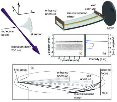
A scheme of the experimental setup is shown in Figure 1. A pulsed molecular beam is generated by expanding 20% CO seeded in krypton or neon through the nozzle of a pulsed supersonic valve (Jordan ToF Products, Inc.). The CO molecules are excited to the upper -doublet component of the , , () level directly from the () rotational level of the electronic and vibrational ground state, using narrow-band pulsed laser radiation around 206 nm (1 mJ in a 5 ns pulse with a bandwidth of about 150 MHz). After passing through a skimmer with a 1 mm diameter opening, the metastable CO molecules, which have a radiative lifetime of about 2.6 ms Gilijamse:2007p1477 , reach the elliptical mirror. This microstructured mirror consists of an array of 1254 gold electrodes, each of which are 4 mm long, 10 wide, and approximately 100 nm high. The electrodes are deposited with a 40 center-to-center spacing onto a 1 mm thick glass substrate, creating an active reflective area of 4 mm by 50 mm (Micro Resist Technology GmbH) Meek:2009p055024 . The parameters , and in Equation (2) for this geometry are 1.196, 0.2478, and 80 , respectively. The glass substrate is clamped between two bronze pieces that have been machined such that they bend the glass into an elliptical segment. The ellipse has a major axis of 245.4 mm and a minor axis of 7.1 mm. The elliptical mirror with its holder is mounted on a manipulator that allows the mirror to be translated parallel to either one of the axes of the ellipse. It also allows the angle between the long axis of the ellipse and the molecular beam axis to be accurately adjusted. The movements are actuated by four vacuum compatible piezo motors (New Focus, Model 8354). At the entrance of the mirror there is a 3.5 mm high entrance slit; near the exit there is another aperture, 4 mm wide and 1.2 mm high. Behind the mirror, the spatial distribution of the metastable CO molecules in the (,)-plane is recorded with a 2” imaging micro-channel plate (MCP) detector with phosphor screen and imaged by a fast CCD camera. The detector can be gated by rapidly switching the voltage applied to the entrance surface of the MCP. In most measurements, the signal is integrated over the full arrival time distribution of the molecules in the pulse. In a typical arrangement, the mirror is positioned such that one focus of the ellipse is near the laser excitation point, the other focus is near the MCP detector and the angle is around zero degrees. Panel (a) in Figure 1 shows a gray-scale image of the intensity of the reflected (upper horizontal stripe) and non-reflected (bottom rectangle) molecular beam as recorded by the CCD camera. Next to it, in panel (b), the signal is shown as a function of the -coordinate only, i.e., after integrating the signal along the -axis. The narrow peak corresponds to the signal of the reflected molecules, and the broad plateau to that of the direct beam. Although we could obviously have made the apertures on the elliptical mirror smaller, thereby avoiding transmission of the direct beam all together, having the direct beam is useful for alignment purposes as well as to have an internal calibration for the amount of reflected molecules.
Before installing the elliptical mirror, we characterized the free molecular beam, using the gated two-dimensional imaging detector. For the beam of CO seeded in neon a Gaussian velocity distribution with a mean velocity of 1000 m/s and with a full width at half maximum (FWHM) of 100 m/s is found. The transverse velocity distribution is also found to be Gaussian and the angular distribution has a FWHM of 33 mrad. When seeded in krypton the mean velocity of the CO molecules is reduced to 560 m/s, their FWHM velocity spread is about 60 m/s and the angular distribution is broadened to a FWHM of 60 mrad.
IV Measurements and simulations
After placing the mirror in the molecular beam machine, we systematically optimized its position for optimum focusing of CO molecules with a mean velocity of 1000 m/s with =150 V applied to the electrodes. The best focusing is obtained when the center of the ellipse is 1.2 mm above the molecular beam axis. The narrowest waist of the reflected beam is achieved when the first focus of the ellipse is placed close to the nozzle while the MCP is a few millimeters in front of the second focus. This effect, namely that the tightest waist is not at the second focus of the ellipse, is also seen in the trajectory simulations and is due to aberrations induced by the fact that the molecular source is not a point source.
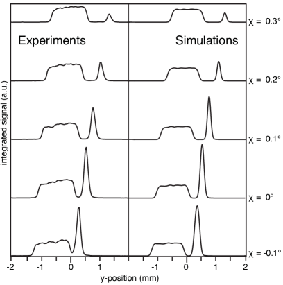
On the left-hand side of Figure 2, the measured signal intensity is shown as a function of the -position, i.e., after integrating the two-dimensional image along the -axis, for different values of the tilt angle . The largest intensity gain of the reflected beam relative to the direct beam under these conditions is about a factor 3, found at a tilt angle close to zero. For more negative angles the intensity of the reflected beam broadens and eventually merges with the direct beam (measurements not shown). At more positive angles the intensity of the reflected beam gradually decreases as the velocity component perpendicular to the mirror surface increases and the molecules crashes into the substrate.
Trajectory calculations have been performed to simulate the recorded two-dimensional images and the height profiles. For these calculations, the known experimental geometry, the measured velocity distribution of the free beam and the strength of the electric field above the elliptical mirror as given by Equation (2) are taken as input. The effective dipole moment, , of the metastable CO molecules in the selected rotational levels is the negative derivative of the Stark energy of these levels with respect to the strength of the electric field and can be written as
| (3) |
In this expression, is the magnitude of the -doublet splitting (394 MHz for the and 1151 MHz for the level Wicke:1972p5758 ), M is the product of the projection of the electronic angular momentum on the internuclear axis with the projection of the total angular momentum on an external axis and is the magnitude of the body-fixed electric dipole moment in the state (1.37 Debye Wicke:1972p5758 ).
Simulated height profiles for different values of the tilt angle are shown on the right hand side of Figure 2. The main features observed in the experiment are reproduced by the trajectory simulations. The calculated distributions of reflected molecules have a minimum width of about 200 (FWHM), implying a reduction of about a factor five relative to the size of the source. The fraction of molecules that approach the surface of the elliptical mirror at closer than the distance () is about 10%, substantiating the assumption that the corrugation of the electric field close to the mirror surface can be neglected.
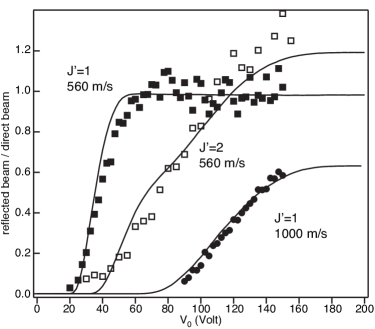
In another set of measurements we have studied the reflectivity of the mirror at a fixed position and orientation, for beams of metastable CO molecules in different rotational levels and with different mean velocities, as a function of the voltages applied to the electrodes. The position of the mirror was similar to the one that returned the data of Figure 2 for , where the groups of molecules that reach the detector directly and those that reach it only after being reflected are clearly separated. In this position, the mean angle of incidence of the molecules on the mirror is between and . The collected data (markers) are shown in Figure 3 together with the outcome of trajectory simulations (lines). The data-points represent the ratio of the number of molecules in the reflected beam to that in the direct beam. The full (empty) squares are the data for metastable CO molecules in the () level seeded in krypton, and the circles are the data for a beam of metastable CO molecules in the level seeded in neon. As expected, higher voltages are needed to reflect the faster CO molecules. The faster beam also yields lower overall ratios of the number of reflected molecules to the number of molecules in the direct beam due to the lower divergence. For a beam with a given mean velocity, lower voltages are required to reflect CO molecules in the level than in the level, in accordance with the larger effective dipole moment of the former level (see Equation (3)). The upper -doublet component of the level splits into four low-field-seeking states (the doubly degenerate and states) and one non-degenerate state, whereas the level splits into two low-field-seeking states and one non-degenerate state. This explains the 20% higher (4/5 versus 2/3) asymptotic ratio in Figure 3 for the level than for the level.
V Discussion and conclusion
We have demonstrated that an electrostatic elliptical mirror can be used to focus molecules coming through a circular skimmer opening into a line-focus further downstream. The focusing properties of the mirror and its dependence on the quantum state of the molecules, on the velocity of the molecules and on the voltages applied to the electrodes is quantitatively understood. Producing the elliptical mirror with microstructured electrodes has the advantage that the actual reflection takes place in a thin region above the surface, with a thickness that is a fraction of the periodicity of the electrode array. Near the outer edge of the reflective region, the corrugation of the electric field strength can be neglected. When the mirror is used under grazing incidence angles, as done here, the corrugation of the electric field as experienced by the molecules is averaged out, and can then also be neglected deeper in the reflective region, i.e., closer to the surface. The mirror therefore acts as a “hard mirror” and its effective reflective surface closely follows the shape of the substrate on which the electrodes are positioned. We have used this here to shape the originally flat structure into a plano-elliptical structure, but other structures can certainly be made as well with this approach.
As stated in the Introduction, we plan to use this elliptical mirror to increase the density of molecules trapped on a molecule chip. The molecule chip we have used thus far is actually exactly the same as the one used for the elliptical mirror, but instead of two static voltages (), six time-dependent (sinusoidal) voltages are then applied to the electrodes. It has been detailed elsewhere that this creates an array of 4 mm long, about 15–20 diameter cylindrical traps for molecules in low-field-seeking quantum states above the chip Meek:2008p153003 ; Meek:2009p055024 . Molecules from a molecular beam can be confined in these tubular traps near the entrance of the molecule chip, provided these traps move with the same speed as the molecules in the molecular beam. When these traps are subsequently decelerated to a standstill, the molecules stay confined in the stationary traps above the chip Meek:2009p1699 . To increase the density of molecules on the chip, we need to match the spatial distribution of the molecular beam near the entrance of the molecule chip to the tubular shape of the traps. It is clear from the experiments that we have described here, that this is what the elliptical mirror does. This alone is not sufficient, however, because the focusing of the molecules in the -direction necessarily leads to an increase of the width of the velocity distribution in the -direction. What is needed is that the (, ) phase-space distribution near the entrance of the molecule chip matches the corresponding phase-space acceptance of the tubular traps.
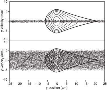
In Figure 4 the calculated (, ) phase-space acceptance of the molecule chip is shown. If the entrance of the molecule chip is positioned about 25 cm away from the molecular beam source, as we have done thus far Meek:2009p1699 , and the molecules are coupled onto the chip without the elliptical mirror in place, the vertical phase-space distribution of the beam is poorly matched to the vertical acceptance. This is shown in the upper panel, where the width of the velocity distribution (indicated by the dots) is much narrower than what could be accepted by the traps. This changes dramatically when the elliptical mirror is placed in between the beam source and the molecule chip. As shown in the lower panel, the width of the velocity distribution now nicely matches the velocity acceptance of the traps. The accompanying reduction of the spatial distribution in the -direction is irrelevant in this case, as the traps are spatially overfilled anyway. Obviously, the molecule chip now needs to be tilted relative to the molecular beam axis such that the -distribution is centered around zero; a tilt angle of about 3.2∘ is assumed in the simulations. It is seen from this comparison that an increase in the density of molecules on the chip of up to an order of magnitude can be expected when the elliptical mirror is implemented. Apart from an improved matching of the beam to the acceptance of the trap, the state selection provided by the mirror is expected to be an important advantage for future experiments.
Acknowledgements.
This work has been funded by the European Community’s Seventh Framework Program FP7/2007-2013 under grant agreement 216 774 and ERC-2009-AdG under grant agreement 247142-MolChip. G.S. gratefully acknowledges the support of the Alexander von Humboldt Foundation.References
- (1) S. A. Meek, H. L. Bethlem, H. Conrad, and G. Meijer, Phys. Rev. Lett. 100 (2008), 153003.
- (2) S. A. Meek, H. Conrad, and G. Meijer, New J. Phys. 11 (2009), 055024.
- (3) S. A. Meek, H. Conrad, and G. Meijer, Science 324 (2009), 1699.
- (4) J. P. Gordon, H. J. Zeiger, and C. H. Townes, Phys. Rev. 95 (1954), 282.
- (5) H. G. Bennewitz, W. Paul, and C. Schlier, Z. Physik 141 (1955), 6.
- (6) K. H. Kramer and R. B. Bernstein, J. Chem. Phys. 42 (1965), 767.
- (7) S. A. Schulze, H. L. Bethlem, J. van Veldhoven, J. Küpper, H. Conrad, and G. Meijer, Phys. Rev. Lett. 93 (2004), 020406.
- (8) M. Metsälä, J. J. Gilijamse S. Hoekstra, S. Y. T. van de Meerakker, and G. Meijer, New J. Phys. 10 (2008), 053018.
- (9) L. D. White, Ammonia maser work at Bell telephone laboratories, Proceedings of the 13th Annual Symposium on Frequency Control, IEEE, 1959, p. 596.
- (10) S. Y. T. van de Meerakker, H. Bethlem, and G. Meijer, Nat. Phys 4 (2008), 595.
- (11) S. J. Wark and G. I. Opat, J. Phys. B: At. Mol. Opt. Phys. 25 (1992), 4229.
- (12) K. Fladischer, H. Reingruber, T. Reisinger, V. Mayrhofer, W. E. Ernst, A. E. Ross, D. A. MacLaren, W. Allison, D. Litwin, J. Galas, S. Sitarek, P. Nieto, D. Barredo, D. Farías, R. Miranda, B. Surma, A. Miros, B. Piatkowski, E. Søndergård, and B. Holst, New J. Phys. 12 (2010), 033018.
- (13) K. Yamamura, M. Nagano, N. Zettsu, D. Yamazaki, R. Maruyama, and K. Soyama, Nucl. Instrum. Methods A 616 (2010), 193.
- (14) J. J. Gilijamse, S. Hoekstra, S. A. Meek, M. Metsälä, S. Y. T van de Meerakker, G. Meijer, and G. C Groenenboom, J. Chem. Phys. 127 (2007), 221102.
- (15) B. G. Wicke, R. W. Field, and W. Klemperer, J. Chem. Phys. 56 (1972), 5758.