Scattering Lens Resolves sub- nm Structures with Visible Light
Abstract
The smallest structures that conventional lenses are able to optically resolve are of the order of nm. We introduce a new type of lens that exploits multiple scattering of light to generate a scanning nano-sized optical focus. With an experimental realization of this lens in gallium phosphide we have succeeded to image gold nanoparticles at nm optical resolution. Our work is the first lens that provides a resolution in the nanometer regime at visible wavelengths.
Many essential structures in nanoscience and nanotechnology, such as cellular organelles, nanoelectronic circuits, and photonic structures, have spatial features in the order of nm. The optical resolution of conventional lenses is limited to approximately nm by their numerical aperture and therefore they cannot resolve nanostructure. With fluorescence based imaging methods it is possible to reconstruct an image of objects that are a substantial factor smaller than the focus size by exploiting the photophysics of extrinsic fluorophores.Hell and Wichmann (1994); Dyba and Hell (2002); Betzig et al. (2006); Rust et al. (2006); Hell (2007) Their resolution strongly depends on the shape of the optical focus, which is determined by conventional lens systems. This dependence makes them vulnerable to focal distortion by scattering. Moreover, its not always feasible or desirable to dope the object under study. Other imaging methods improve their resolution by reconstructing the evanescent waves that decay exponentially with distance from the object. Intricate near field microscopes bring fragile nano-sized probes in close proximity of the object where the evanescent field is still measurable.Pohl and Courjon (1993) With this technique it is hard to quantify the interaction between the short-lived tip and the structure. Metamaterials, which are meticulously nanostructured artificial composites, can be engineered to access the evanescent waves and image sub-wavelength structuresPendry (2000) as demonstrated with superlensesFang et al. (2005) and hyperlensesLiu et al. (2007) in the UV. These materials physically decrease the focus size, which brings the possibility for improvement of both linear and non-linear imaging techniques. In the especially relevant visible range of the spectrum, plasmonic metamaterials can be used to produce nano-sized isolated hot spotsStockman et al. (2002); Aeschlimann et al. (2007); Kao et al. (2011) but the limited control over their position makes them unsuitable for imaging. Up to now, a freely scannable nano-sized optical focus has not been demonstrated.
In this Letter we introduce a new type of lens that generates a scanning nano-sized optical focus. We used this lens to image a collection of gold nanoparticles at 97 nm optical resolution. The lens exploits multiple scattering of light in a porous high refractive index material to increase the numerical aperture of the system; a principle we name High Index Resolution Enhancement by Scattering (HIRES).
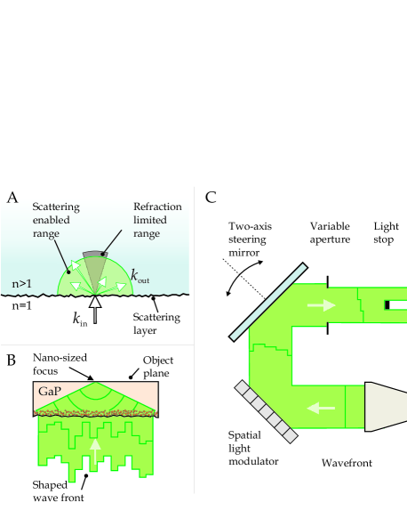
A HIRES-lens consists of a homogenous slab of high-index material on top of a strongly disordered scattering layer. The disordered layer breaks the translational invariance of the interface, which enables incident light to be coupled to all propagating angles inside the high-refractive-index material as is shown in Fig. 1A. Yet multiple scattering also scrambles the wavefront creating a speckle-like pattern on the object plane that itself cannot be used for imaging. Therefore we manipulate the incident wavefront in order to force constructive interference of the scattered light at a position in the object plane of our HIRES-lens. The wavefront is controlled using a feedback based methodVellekoop and Mosk (2007) that is conceptionally related to phase conjugationLeith and Upatnieks (1966) and time reversalFink et al. (2000). As a result, a perfectly spherical wave emerges from the porous layer and converges towards the object plane to form a sharp optical focus (Fig. 1B). Whereas in conventional optics (e.g. solid immersion lensesWu et al. (1999) or total internal reflection microscopesAxelrod et al. (1984)) any inevitable surface roughness causes a distortion of the wavefront and a concomitant loss of resolution, the inherent random nature makes a HIRES-lens robust for these abberations. Any wavefront error is distributed randomly over all outgoing directions, slightly reducing the contrast but not the resolutionVellekoop et al. (2010). In order to use the HIRES-lens for high resolution imaging, the focus is easily moved around in the object plane by steering the incident wavefront directly exploiting the angular correlations in the scattered light; an effect well known as the optical memory effect.Feng et al. (1988); Freund et al. (1988); Vellekoop and Aegerter (2010) By raster scanning the focus across an object we acquire an abberation-free high resolution image. The robust scanning high resolution focus makes the HIRES-lens excellently suited for optical imaging of nanostructures.
To demonstrate an experimental implementation of our HIRES-lens we fabricate it in gallium phosphide (GaP). GaP is transparent in a large part of the visible spectrum ( nm) and has a maximum refractive index of n=, higher than any other transparent material in this wavelength range.Aspnes and Studna (1983) Electrochemically etching GaP with sulfuric acid (H2SO4) creates macroporous networks resulting in one of the strongest scattering photonic structures ever observed.Schuurmans et al. (1999) Using this etching process we create a m thick porous layer on one side of a crystalline GaP wafer. This layer is thick enough to completely randomize the incident wavefront and to suppress any unscattered background light.
The optical memory effect allows us to shift the scattered light in the object plane of the HIRES-lens over a distance before the intensity correlation decreases to Feng et al. (1988), where m is the thickness of the wafer. The loss of correlation only affects the intensity in the focus (not its shape) making it easy to correct for this effect without losing resolution. Due to the high refractive index contrast on the flat GaP-air interface, a large fraction of the light is internally reflected. The reflected light interferes with the light that comes directly from the porous layer. This interference causes a background signal that is times larger than the focus intensity. We have therefore strongly suppressed the internal reflections by depositing an approximately nm thick anti-internal-reflection coating of amorphous silicon on the surface. The amorphous silicon is nearly index matched with the GaP and strongly absorbs the light that would otherwise be internally reflected. As a result of this layer, the background signal is significantly reduced to only times the focus intensitySup (2011). The resulting field of view of our coated HIRES-lens is measured to be m in radius; of the theoretical limit determined by the optical memory effect. In the center of the surface we created a small window of about m in diameter by locally removing the anti-internal-reflection coating. We use this window to place objects onto our HIRES-lens. As a test sample we have deposited a random configuration of gold nanoparticles with a specified diameter of nm inside this window.
An overview of our setup is shown in Fig. 1C. We use a CW laser with a wavelength of nm just below the GaP bandgap of eV ( nm) where the refractive index is maximal and the absorption is still negligible.Aspnes and Studna (1983) We spatially partition the wavefront into square segments of which we independently control the phase using a spatial light modulator (SLM). The SLM is first imaged onto a two-axis fast steering mirror and then onto the porous surface of the HIRES-lens. With a variable aperture we set the radius of the illuminated surface area between m and m. The visibility of the gold nanoparticles is maximized by blocking the central part of the illumination (m), placing the system in a dark field configuration. At the back of the HIRES-lens a high-quality oil immersion microscope objective (NA = ) images the object plane onto a CCD camera. This objective is used to efficiently collect all the light scattered from the object plane and to obtain an reference image which is used as a comparison for our HIRES-lens. Notice that in our scheme the resolution is determined by the HIRES-lens itself and does not depend on the imaging optics at the back.
We first synthesize the wavefront that, after being scattered, creates a focus in the object plane. We use light scattered from one of the gold nanoparticles in the object plane as a feedback signal to obtain a set of complex amplitudes that describe the propagation from different incident positions on the porous layer towards the nanoparticleVellekoop and Mosk (2007). By reversing the phase of these complex amplitudes we force the light waves to interfere constructively at the exact location of the nanoparticle. The focus is moved around in the image plane by rotating every contributing k-vector over a corresponding angle. We apply these rotations by adding a deterministic phase pattern to the incident wavefront. In the paraxial limit, a simple tilt of the wavefront would suffice to displace the focus.Vellekoop and Aegerter (2010); Hsieh et al. (2010) For our high resolution focus, which lies beyond this limit, an additional position dependent phase correction is required that we apply using the SLM.Sup (2011) The addition of this correction is essential for a proper displacement of the focus.
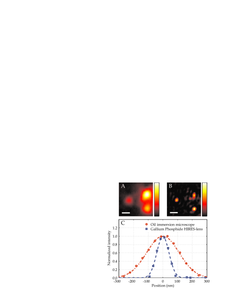
In Fig. 2 we show the imaging capabilities of the GaP HIRES-lens. First a reference image was acquired with the high-quality microscope behind the HIRES-lens (Fig. 2A). Because the size of the gold nanoparticles is much smaller than the resolution limit of this conventional oil immersion microscope the image of the nanoparticles is blurred. Next we used our HIRES-lens to construct a high-resolution image. By manipulating the wavefront a focus was generated on the leftmost nanoparticle. We raster scanned the focus across the object plane while we constantly monitored the amount of scattered light. In Fig. 2B the result of the scan is shownSup (2011). A cross section through the center of the left sphere (Fig. 2C) clearly shows the improvement in resolution we obtained with our HIRES-lens, confirming our expectations that the resolution of this image is far better than that of the conventional high-quality detection optics.
For a more quantitative study of the obtained resolution, we study the shape of the focus in the HIRES-lens. The radial intensity distribution of the focus is directly calculated from a plane wave decomposition of the contributing waves,
| (1) |
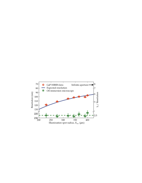
where is a Bessel function of the first kind. The minimum and maximum coupled transversal k-vectors, and , are directly related to the inner and outer radius, and , of the illuminated area: (and similar for ). To confirm this dependence, we imaged the objects for different values of the illumination radius . For each measurement the resolution is determined by modeling the resulting image of a single nm gold nanoparticle with Eq. 1. Since it is hard to quantify the resolution from the width of a non-Gaussian focal shape we use Sparrow’s criterion which defines the resolution as the minimal distance at which two separate objects are still discernible, see e.g. Hecht (1998). In Fig. 3 the measured resolution versus is shown. As a reference we also plotted the measured resolution of the high-quality oil immersion microscope. We see that the resolution improves as we increase the illuminated area. The measured resolutions are in excellent correspondence with the expected resolution obtained from the calculated intensity profile. The resolution of the HIRES-lens is much better than the high-quality conventional oil immersion microscope. The highest resolution we measured is nm, which demonstrates imaging in the nanometer regime with visible wavelengths.
A GaP HIRES-lens has the potential to reach even better optical resolutions up to nm. It is then possible to resolve objects placed in each others near field at distances of . To achieve these resolutions a wider area of the scattering porous layer has to be illuminated and as a result light has to be scattered at increasingly higher angles from the porous layer. Here advances could benefit from investigations in the field of thin film solar cells where high angle scattering is beneficial for optimal light harvestingYablonovitch and Cody (1982).
Our results open the way to improve resolution in a wide range of optical imaging techniques. The robustness of a HIRES-lens against distortion and abberation, together with their ease to manufacture, makes them ideal for the imaging of fluorescent labeled biological samples or for the efficient coupling to metamaterialsFang et al. (2005); Liu et al. (2007) and plasmonic nanostructuresStockman et al. (2002); Aeschlimann et al. (2007); Kao et al. (2011). Recent developments in spatio-temporal control of waves in disordered materialsAulbach et al. (2011); Katz et al. (2011); McCabe et al. (2011) suggest the possibility for HIRES-lenses to create ultrashort pulses in a nano-sized focus. The fact that a HIRES-lens is a linear technique opens the possibility to use it for resolution improvement of a large range of existing linear and non-linear imaging techniques, such as confocal microscopy, STEDDyba and Hell (2002), PALMBetzig et al. (2006), and STORMRust et al. (2006).
I Acknowledgements
The authors would like to acknowledge Hannie van den Broek, Cock Harteveld, Léon Woldering, Willem Tjerkstra, Ivo Vellekoop, Christian Blum, and Vinod Subramaniam for their support and insightful discussions. This work is part of the research program of the “Stichting voor Fundamenteel Onderzoek der Materie (FOM)”, which is financially supported by the “Nederlandse Organisatie voor Wetenschappelijk Onderzoek (NWO)”. JB is partially financed by the FIRB-MIUR ”Futuro in Ricerca” project RBFR08UH60. WLV thanks NWO-Vici and APM is supported by a Vidi grant from NWO.
References
- Hell and Wichmann (1994) S. W. Hell and J. Wichmann, Opt. Lett. 19, 780 (1994).
- Dyba and Hell (2002) M. Dyba and S. W. Hell, Phys. Rev. Lett. 88, 163901 (2002).
- Betzig et al. (2006) E. Betzig, G. H. Patterson, R. Sougrat, O. W. Lindwasser, S. Olenych, J. S. Bonifacino, M. W. Davidson, J. Lippincott-Schwartz, and H. F. Hess, Science 313, 1642 (2006).
- Rust et al. (2006) M. J. Rust, M. Bates, and X. Zhuang, Nat. Meth. 3, 793 (2006), ISSN 1548-7091.
- Hell (2007) S. W. Hell, Science 316, 1153 (2007).
- Pohl and Courjon (1993) D. Pohl and D. Courjon, Near Field Optics (Kluwer, Dordrecht, 1993).
- Pendry (2000) J. B. Pendry, Phys. Rev. Lett. 85, 3966 (2000).
- Fang et al. (2005) N. Fang, H. Lee, C. Sun, and X. Zhang, Science 308, 534 (2005).
- Liu et al. (2007) Z. Liu, H. Lee, Y. Xiong, C. Sun, and X. Zhang, Science 315, 1686 (2007).
- Stockman et al. (2002) M. I. Stockman, S. V. Faleev, and D. J. Bergman, Phys. Rev. Lett. 88, 067402 (2002).
- Aeschlimann et al. (2007) M. Aeschlimann, M. Bauer, D. Bayer, T. Brixner, F. J. Garcia de Abajo, W. Pfeiffer, M. Rohmer, C. Spindler, and F. Steeb, Nature 446, 301 (2007), ISSN 0028-0836.
- Kao et al. (2011) T. S. Kao, S. D. Jenkins, J. Ruostekoski, and N. I. Zheludev, Phys. Rev. Lett. 106, 085501 (2011).
- Vellekoop and Mosk (2007) I. M. Vellekoop and A. P. Mosk, Opt. Lett. 32, 2309 (2007).
- Leith and Upatnieks (1966) E. N. Leith and J. Upatnieks, J. Opt. Soc. Am. 56, 523 (1966).
- Fink et al. (2000) M. Fink, D. Cassereau, A. Derode, C. Prada, P. Roux, M. Tanter, J.-L. Thomas, and F. Wu, Rep. Prog. Phys. 63, 1933 (2000).
- Wu et al. (1999) Q. Wu, G. D. Feke, R. D. Grober, and L. P. Ghislain, Appl. Phys. Lett. 75, 4064 (1999).
- Axelrod et al. (1984) D. Axelrod, T. P. Burghardt, and N. L. Thompson, Annu. Rev. Biophys. Bioeng. 13, 247 268 (1984).
- Vellekoop et al. (2010) I. Vellekoop, A. Lagendijk, and A. Mosk, Nat Photon 4, 320 (2010).
- Feng et al. (1988) S. Feng, C. Kane, P. A. Lee, and A. D. Stone, Phys. Rev. Lett. 61, 834 (1988).
- Freund et al. (1988) I. Freund, M. Rosenbluh, and S. Feng, Phys. Rev. Lett. 61, 2328 (1988).
- Vellekoop and Aegerter (2010) I. Vellekoop and C. Aegerter, Opt. Lett. 35, 1245 (2010).
- Aspnes and Studna (1983) D. E. Aspnes and A. A. Studna, Phys. Rev. B 27, 985 (1983).
- Schuurmans et al. (1999) F. J. P. Schuurmans, D. Vanmaekelbergh, J. van de Lagemaat, and A. Lagendijk, Science 284, 141 (1999).
- Sup (2011) Details on materials and methods are forthcoming. (2011).
- Hsieh et al. (2010) C.-L. Hsieh, Y. Pu, R. Grange, G. Laporte, and D. Psaltis, Opt. Express 18, 20723 (2010).
- Hecht (1998) E. Hecht, Optics (Addison Wesley Longman, Inc., 1998).
- Yablonovitch and Cody (1982) E. Yablonovitch and G. D. Cody, IEEE Trans. Electron Devices 29, 300 (1982).
- Aulbach et al. (2011) J. Aulbach, B. Gjonaj, P. M. Johnson, A. P. Mosk, and A. Lagendijk, Phys. Rev. Lett. 106, 103901 (2011).
- Katz et al. (2011) O. Katz, Y. Bromberg, E. Small, and Y. Silberberg, arXiv:1012.0413 (2011).
- McCabe et al. (2011) D. J. McCabe, A. Tajalli, D. R. Austin, P. Bondareff, I. A. Walmsley, S. Gigan, and B. Chatel, arXiv:1101.0976 (2011).