Coupled-resonator-induced transparency with a squeezed vacuum
Abstract
We present the first experimental observation of quantum fluctuation spectra in two coupled optical cavities with an injected squeezed vacuum light. The quadrature components of the reflected squeezed vacuum spectra are measured by phase sensitive homodyne detector. The experimental results demonstrate coupled-resonator-induced transparency in the quantum regime, in which electromagnetically-induced-transparency-like characteristic of the absorption and dispersion properties of the coupled optical cavities determines the line-shape of the reflected quantum noise spectra.
The squeezed vacuum as a vital source of quantum entanglement enable us to implement a variety of quantum information protocols deterministically eight ; nine . Propagation, storage, and manipulation of the squeezed vacuum and entanglement are essential for quantum information processing eight ; nine . Recent experiments have demonstrated the transmission one , slowing down two ; three ; four , storage and retrieval five ; six of squeezed states of light through electromagnetically induced transparency (EIT) in multi-level atomic systems seven . The manipulations of squeezed vacuum and two-mode entangled state by means of a phase-sensitive optical amplifier seven1 have also been achieved experimentally.
EIT in atoms comes from quantum destructive interferences between excitation pathways to the upper level of an atomic three-level system seven . It has been proved that there are analogical phenomena of the coherence and interference process in some classical physical systems, such as plasma ten , coupled optical resonators eleven ; eleven0 ; eleven1 , mechanical or electric oscillators twelve , and optical parametric oscillators thirteen . Particularly, the analog of EIT in coupled optical resonators including the capabilities of slowing, stopping, storing and time reversing an incident optical pulse have made great progress in experiment recently, which have been reported for observing the structure of the EIT-like spectrum in a compound glass waveguide platform using relatively large resonators forteen , coupled fused-silica microspheres fifteen ; sixteen , integrated micron-size silicon optical resonator systems seventeen , photonic crystal cavities eighteen , and fiber ring resonators nineteen . These works also open up the new possibility of utilizing coupled optical resonators to realize the optical communication and the simulation of coherent effect in quantum optics. In this Letter, we report the first experimental observation of quantum fluctuation spectra in two coupled optical cavities with an injected squeezed vacuum state. Using the phase sensitive homodyne detection setup with a local oscillator beam, the line-shapes of the quantum noise spectra of the output squeezed vacuum are experimentally measured, which clearly exhibit the EIT-like characteristic of the absorptive and dispersive properties in two coupled optical cavities. We are sure that the results demonstrated in the experiment using coupled two large optical cavities can be obtained identically in micro-structure devices if on-chip coupled optical cavities are used, and thus it has potential applications in the manipulation of optical quantum states.
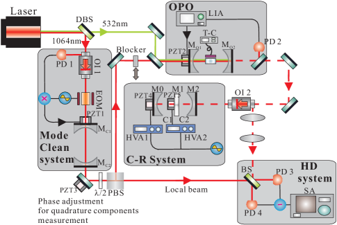
The experimental setup (Fig. 1) consists of five parts including a laser source, a mode clean system, an optical parametric oscillation (OPO), coupled optical resonators (C-R system), and homodyne detection (HD) system. The laser source is a diode-pumped intracavity frequency-doubled (continuous-wave ring Nd:YVO4+KTP) laser, which provides the second-harmonic light of 200 at 532 and the fundamental light of 50 at 1064 simultaneously. The fundamental light is injected into a mode clean system which is served as spatial mode cleaner. The fundamental light is divided into two optical beams after it passes through the mode clean cavity, one of which is used for the local oscillator in the HD system, and the other one is sent into the OPO to be as the signal field for the alignment of both OPO cavity and the C-R system. When this signal beam injected into OPO is blocked by a movable blocker and only the pump light at 532 exists, the output of OPO will be a squeezed vacuum. The configuration of the OPO is a near concentric optical cavity consisting of two concave mirrors and of 30 curvature radius with a separated distance of and a 12 long PPKTP (periodically poled KTP) crystal is place at the center position of the cavity. The PPKTP crystal is mounted in a copper block for actively controlling its temperature at the phase-matching temperature. The input coupler of the OPO cavity has a reflectivity of 99.5 at 1064 and 30 at 532 , which is mounted on a piezoelectric transducer (PZT2) for the adjustment of the cavity length. The reflectivity of the output coupler is 88.7 at 1064 and it is coated to be a high reflector ( 99) for 532 . In such a coated optical cavity the power of the second-harmonic wave can be built up to a few times of the input power when the fundamental wavelength is on resonance with the cavity. The squeezed vacuum generated by OPO is injected into the coupled resonators through an optical isolator, which separates the reflection field of the coupled resonators from the injected field. The squeezing degree of the squeezed vacuum generated by the OPO is measured by a balanced homodyne detector consisting of a 50 beam splitter, where the squeezed vacuum and the local beam are combined, as well as a pair of Epitaxx ETX-500T photodiodes. Adjusting the spatial mode of reflected beam from the coupled cavities, an interference fringe visibility of 94 between local oscillator and the reflected beam was achieved in the experiment.
The C-R system in Fig. 1 involves the two coupled resonators consisting of two standing wave cavities, which are constructed by M0, M1, and M2. M0 and M2 are the concave mirrors of 30 curvature radius with a separation of 59 . M1 is a plane mirror mounted on a PZT5, which is inserted at the middle between M0 and M2. One surface of M1 facing to M2 is coated with anti-reflection for 1064 and the other surface facing to M0 is coated with partial reflectivity for 1064 . The two directly coupled optical cavities (C1 and C2) are in the same geometric structure, and the coupling strength between C1 and C2 depends on the reflectivity of the middle mirror M1. The PZT 4 and 5 mounted on the mirrors M0 and M1 are used for controlling the cavity length of C1 and C2, respectively. The reflectivity of M2 is 96.8 and M0 is high reflectivity for 1064 . When the reflectivity of M1 is chosen to be (case I) and (case II) respectively, two kinds of coupled resonators with different coupling strength are constructed.
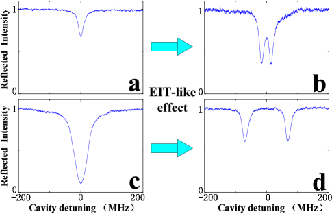
Before injecting the squeezed state into the two coupled cavities, we first characterize the two coupled cavities in the classical field by injecting a coherent signal beam at the subharmonic wavelength. When the pump beam is blocked, the OPO cavity is locked on resonance with the fundamental field by a lock-in amplifier and the transmitted light at 1064 is injected into the coupled resonator system to be the signal beam. The intensity of the reflected field of the coupled resonators extracted by an optical isolator is detected directly by a photodiode. When we blocked the cavity C1 of the coupled cavities, the reflected intensity from the cavity C2 during scanning the cavity length are a simple Lorentzian profile as shown in the Fig. 2(a) and (c). Fig. 2(a) and (c) correspond to the over-coupled optical cavity for the experimental parameters (case I) and the near critically-coupled optical cavity (case II), respectively. Then we open the cavity C1 to study the features of the two coupled optical cavities. Usually the reflected intensity with the injected coherent signal light are measured by adjusting two cavities to be co-resonant and scanning the laser frequency fifteen ; sixteen ; seventeen . Here we employ an equivalent way to measure the intensity of the reflected light, that is to keep the laser frequency unchanged and scan the length of the two cavities. A high voltage amplifier (HVA1), which that drives the PZT4 actuating the mirror M0 uses the same scanning signal source with the HVA2 driving the PZT5 for the mirror M1. So, when the gain of HVA1 is two times larger than that of HVA2, the reflected intensity by scanning the length of two cavities are equivalent to scanning the laser frequency. As we can see in the Fig. 2(b), a transparent window appeared in the middle of the absorption profile due to the existence of the cavity C2. The destructive interference between the two optical pathways results in the transparent peak, which is named as a coupled-resonator-induced transparency. This transparent peak becomes broader when the coupling strength is increased and the original mode eventually is split into two modes (as shown in Fig. 2(d)).
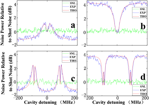
Now, let’s inject the squeezed vacuum state into the coupled optical cavitied system to investigate the coupled-resonator-induced transparency effect formed by the quantum field. A quadrature squeezed vacuum state with about 1.6 squeezing component and 4 antisqueezing component at the sideband frequency of 2.5 is generated from the subthreshold OPO when we block the signal beam of 1064 light and only approximate 50 pump beam of 532 is applied. Similarly, the reflection spectra of the squeezed vacuum light from the cavity C2 is examined by scanning M1 with PZT5 when blocking the cavity C1 of the coupled cavities, firstly. Fixing the relative phase between the local beam and the squeezed vacuum light reflected by the cavity C2 to be (or by tuning the PZT3, we can obtain the squeezing (or antisqueezing) component of the reflected quadrature spectra at far off resonance. Because of the absorption and dispersion properties of the single optical cavity, the reflected spectra of quantum fluctuation near resonance will be changed twenty1 . Fig. 3(a) and Fig. 4(a) show the reflected quadrature spectra of the squeezing component for the experimental parameters of case I and II respectively, and Fig. 3(b) and Fig. 4(b) show the corresponding antisqueezing component. The lineshape of the reflected spectrum of the squeezed component for the over-coupled optical cavity (case I) presents M profile (Fig. 3(a)), and the two shoulders at detuning frequencies are higher, which is due to the lower loss and larger phase shift in the over-coupled cavity. The two shoulders in the profile corresponds to the phase shift of induced by the cavity. The degree of the squeezing at zero detuning is below the SNL and will reach the degree of the input squeezing for the strongly over-coupled cavity. The noise spectrum of the antisqueezed component presents the W profile as shown in Fig. 3(b). The noise level at zero detuning will reach the level of the input antisqueezing component for the strongly over-coupled cavity. Since the amplitude of the reflected field is zero at resonance for critically-coupled cavity (case II), the lineshape of the reflected spectrum of the squeezed component also presents M profile (Fig. 4(a)), however the two shoulders are lower than that of case I. The reflected spectrum of the antisqueezing component presents V profile and only one dip locates at resonance (Fig. 4(b)).
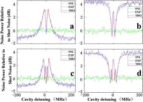
Now, we open the cavity C1 to build up the coupled resonators system. The reflection spectra for the squeezed vacuum light are studied by the way of scanning the length of two cavities as described above. Fig. 3(c), Fig. 4(c) and Fig. 3(d), Fig. 4(d) show the reflected quadrature spectra of the squeezing and antisqeezing components for the experimental parameters of case I and II respectively. For two coupled resonators with weak coupling strength, two extra dips appear respectively in the two shoulders of the reflected spectrum for the squeezed component (three dips appear in the center of a broader peak as shown in Fig. 3(c)). Correspondingly, three peaks present in the center of a broader dip for the reflected spectrum of the antisqueezing component (Fig. 3(d)). These extra dips and peaks are induced by the dispersion characteristic of the coupled-resonator-induced transparency, which presents three points of crossing the zero phase shift. For the case of large coupling strength, in which the original mode splits into two, two independent M profiles (each M profile shows the same lineshape of the reflected spectrum of the squeezed component for the single over-coupled cavity) appear in the detuning frequencies of the reflected spectrum of the squeezed component as shown in Fig. 4(c). Correspondingly, two independent W profiles also appear in the detuning frequencies of the reflected spectrum of the antisqueezed component as shown in Fig. 4(d). In order to make theoretical comparisons with the above experimental results, the reflected spectra for the amplitude and phase quadratures are calculated (see Ref. twenty-one for the detailed theoretical calculation) with experimental parameters. Our theoretically calculated results (red lines) are plotted together with the experimental data in Figs. 3 and 4, which show excellent agreements. This result shows that EIT-like characteristic of the absorption and dispersion properties of the coupled optical cavities determines the line-shape of the reflected quantum noise spectra.
In summary, we have experimentally demonstrated the response of two coupled optical cavities in quantum domain. We developed a method to measure the reflection spectra by scanning the length of two cavities instead of scanning the laser frequency. We gave the reflected quantum fluctuation spectra of the two coupled resonators with two different coupling strength and showed that the line-shapes of the reflected quantum noise spectra depend on the absorptive and dispersive properties of two coupled optical cavities with EIT-like characteristic. This work achieves the first step of manipulating quantum fluctuations using coupled resonators and provides a scheme for the future studies on slow light, storage and retrieval eleven1 of quantum fields. Here we would like to emphasize that the basic requirements of a light-stopping process (capture, storage and release of the light pulse) are that the coupled-resonator system supports a large-bandwidth state to accommodate the input pulse bandwidth, which is then dynamically tuned to an narrow-bandwidth state to stop the pulse and done reversibly after some storage time to release light pulse. Two dynamically tuned resonators for stopping light have been proposed theoretically eleven0 ; twenty-two and demonstrated experimentally twenty-three . Thus this protocol should be feasible to be used to capture, storage and release of squeezed light. The current structure of two coupled cavities in our experiment can not satisfy this requirement completely to tune the cavity bandwidth dynamically. However, the structure with two dynamically tuned resonators above-mentioned for stopping light could be used in our system. We also hope that this work will stimulate the development of manipulating the quantum optical fields with on-chip coupled optical cavities.
Acknowledgements.
This research was supported in part by NSFC for Distinguished Young Scholars (Grant No. 10725416), National Basic Research Program of China (Grant No. 2011CB921601,2010CB923103), NSFC Project for Excellent Research Team (Grant No. 60821004), and NSFC (Grant No. 60736040).References
- (1) S. L. Braunstein and A. K. Pati, Quantum Information with Continuous Variables (Kluwer Academic, Dordrecht, 2003).
- (2) Quantum Information with Continuous Variables of Atoms and Light, edited by N. Cerf, G. Leuchs, and E. S. Polzik (Imperial College Press, London, 2007).
- (3) D. Akamatsu, et al., Phys. Rev. Lett. 92, 203602 (2004).
- (4) D. Akamatsu, et al., Phys. Rev. Lett. 99, 153602 (2007).
- (5) M. Arikawa, et al., Opt. Express 15, 11849 (2007).
- (6) G. Hetet, et al., arXiv:0803.2097 [quant-ph].
- (7) K. Honda, et al., Phys. Rev. Lett. 100, 093601 (2008).
- (8) J. Appel, et al., Phys. Rev. Lett. 100, 093602 (2008).
- (9) S. E. Harris, Phys. Today 50, 37 (1997); M. Fleischhauer, A. Imamoglu, et al., Rev. Mod. Phys. 77, 633 (2005).
- (10) J. Zhang, et al., Phys. Rev. Lett. 101, 233602 (2008); Y. Shang, et al., Opt. Lett. 35, 853 (2010).
- (11) S. E. Harris, Phys. Rev. Lett. 77, 5357 (1996); A. G. Litvak and M. D. Tokman, Phys. Rev. Lett. 88, 095003 (2002); G. Shvets and J. S Wurtele, Phys. Rev. Lett. 89, 115003 (2002).
- (12) D. D. Smith, et al., Phys. Rev. A 69, 063804 (2004).
- (13) L. Maleki, et al., Opt. Lett. 29, 626 (2004).
- (14) M. F. Yanik, et al., Phys. Rev. Lett. 93, 233903 (2004); M. F. Yanik, and S. Fan, Phys. Rev. Lett. 92, 083901 (2004); M. F. Yanik, and S. Fan, Phys. Rev. A 71, 013803 (2005).
- (15) P. R. Hemmer and M.G. Prentiss, J. Opt. Soc. Am. B 5, 1613 (1988); C. L. Garrido Alzar, et al., Am. J. Phys. 70, 37 (2002).
- (16) H. Ma, et al., Phys. Rev. Lett. 95, 233601 (2005); C. Ye and J. Zhang, Opt. Lett. 33, 1911 (2008).
- (17) S. T. Chu, et al., IEEE Photonics Technol. Lett. 11, 1426 (1999).
- (18) A. Naweed, et al., Phys. Rev. A 71, 043804 (2005).
- (19) K. Totsuka, et al., Phys. Rev. Lett. 98, 213904 (2007).
- (20) Q. Xu, et al., Phys. Rev. Lett. 96, 123901 (2006);
- (21) X. Yang, et al., Phys. Rev. Lett. 102, 173902 (2009).
- (22) Y. Dumeige, et al., Phys. Rev. A 78, 013818 (2008).
- (23) B. J. J. Slagmolen, et al., Appl. Opt. 39, 3638 (2000); D. D. Smith, H. Chang, J. Mod. Opt. 51, 2503 (2004).
- (24) M. D. Levenson, et al., Opt. Lett. 10, 514 (1985); P. Galatola, et al., Opt. Commun. 85, 95 (1991); J. Zhang, et al., J. Opt. Soc. Am. B 17, 1920 (2000); A. Zavatta, et al., Phys. Rev. A 66, 043805(2002).
- (25) See EPAPS Document for supplementary material.
- (26) C. R. Otey, et al., Appl. Phys. Lett. 94, 231109 (2009).
- (27) Q. Xu, et al., Nat. Phys. 3, 406 (2007).
SUPPLEMENTARY MATERIAL
In this Appendix we describe in detail theoretical calculations of the quantum fluctuation spectra of the reflected field from the coupled optical cavities. The complex electric-field transmission () from two coupled optical cavities is given by one ; two
| (1) |
where is the complex reflectivity from the first cavity C1
| (2) |
Here, are the round trip phase-shifts, are the refractive indices, are the cavity length, is the frequency of the laser, and specifies the the first or second cavity. are the reflection indices of cavity mirrors, and are the round trip attenuation coefficients. The reflected field given in Eq. (1) can be separated into the amplitude and phase of the coupled cavities
| (3) |
The quantum states we consider in this paper are described with the electromagnetic field annihilation operator , which is expressed in terms of the amplitude and phase quadrature with the canonical commutation relation . Since the quantum fluctuation spectra of the quadrature variances of the reflection field are measured and analyzed, we implement the Fourier transformation . The amplitude and phase quadratures of the reflected field in frequency domain are expressed by
| (4) |
The relationship of the input and reflected quantum fields from two coupled optical cavities is calculated based Eqs. (1) and (3)
| (5) | |||||
where is the vacuum field coupled into the vacuum field due to the loss, is central frequency of quantum field (belong to optical frequency) and is the analysis frequency of the sidebands. Thus we may obtain the amplitude quadrature and its variance of the reflected field
| (6) | |||||
| (7) | |||||
Similarly, we get the variance of the phase quadrature of the reflected field
| (8) | |||||
Here, the variances of the vacuum field are normalized . The variances of the input squeezed vacuum field with squeezing factor can be expressed by , and .
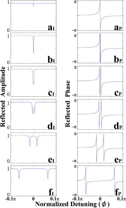
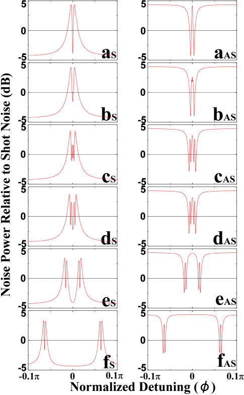
Fig. 1 plots the reflected amplitude and phase of the two coupled cavities as a function of the cavity detuning for different coupling strength by use of Eq. 3. The coupling strength (the reflectivity of center mirror M1) increase with plot alphabet. Fig. 2 plots of the quantum fluctuation spectra of the reflected field from the coupled optical cavities for different coupling strength by use of Eqs. 7 and 8.
References
- (1) D. D. Smith, et al., Phys. Rev. A 69, 063804 (2004).
- (2) D. D. Smith, and H. Chang, J. Mod. Opt. 51, 16 (2004).