Time-resolved imaging of magnetoelectric domain switching in multiferroic MnWO4
Abstract
We show that the electric-field-induced reversal of the magnetic order parameter in multiferroic MnWO4 occurs on the time scale of milliseconds. Throughout the switching process the magnetic order and the magnetically induced electric polarization remain rigidly coupled. The temporal progression of the domain structure was imaged with nanosecond resolution by an electrical-pump–optical-probe technique using optical second harmonic generation. These nonequilibrium domain states significantly differ from the quasi-static domain reversal. A qualitative model gives an estimate of why the magnetoelectric order-parameter reversal in the magnetically induced ferroelectrics is not inherently ultrafast.
pacs:
75.85.+t, 75.78.Fg, 77.80.Fm, 42.65.KyI Introduction: Time-resolved multiferroics
Materials with cross-coupled magnetic and electric properties, called magnetoelectrics, are intensely discussed because of their potential for controlling dielectric or magnetic properties with the crosswise magnetic or electric field .khomskii09 Magnetoelectric effects are intrinsically strong in compounds where magnetic long-range order breaks the inversion symmetry and induces a spontaneous polarization. This mechanism results in a rigid coupling of the improper ferroelectric polarization to the proper magnetic order parameter(s).newnham78 ; kimura03 ; hur04
Despite intensive research on these so-called “multiferroics” one central aspect of the interplay of magnetic and electric order parameters has scarcely been discussed: How does the voltage-induced reversal of the magnetization progress with time? Knowing the dynamics of voltage-induced magnetization reversal would highlight the competition of spins and charges. This would significantly advance our general understanding of the parameters defining the magnetoelectric coupling in one of the most prominent classes of multiferroics. But also with respect to possible applications like memory devices and sensors the switching dynamics is a key issue. For example, the feasibility of any candidate compound for a novel type of memory element depends crucially on its bit-reversal time.
Thus far, investigations of the dynamical properties of multiferroics are devoted to the AC magnetoelectric response of magnetostrictive-piezoelectric composites at microwave frequencies. fiebig05a In two multiferroics the ultrafast response to laser pulse excitation has been investigated.kimel01 ; matsubara09 Yet, in none of these experiments time-resolved magnetoelectric switching processes were observed or discussed. In spite of the significance of this topic investigations are virtually non-existent.
In this Report we show that the electric-field-induced reversal of the magnetic order in multiferroic MnWO4 extends over a surprisingly long time span in the order of milliseconds. The evolution of the multiferroic domain structure throughout the switching process is spatially resolved by optical second harmonic generation and compared to the quasi-static reversal of domains. Fundamental differences between the observed magnetoelectric switching and models for switching of domains in non-multiferroics are highlighted.
II Samples and methods
II.1 Multiferroic MnWO4
The compound investigated here, MnWO4, is prototypical for the group of magnetically induced ferroelectrics:arkenbout06 ; jia07 There is a multitude of similar compounds promoting non-centrosymmetric, preferably frustrated and/or incommensurate spin structures. They can induce spontaneous polarization even up to ambient temperature.kimura08 This background emphasizes the general merit of our results.
Three magnetically ordered phases discussed in detail in Refs. lautenschlaeger93, and toledano09, constitute the phase diagram of MnWO4. In the AF3 phase below K the magnetic moments of Mn2+ align collinearly along the easy axis while their magnitudes are sinusoidally modulated yielding incommensurate order in the plane (axes: see Ref. axes, ). An additional transverse spin component orders at K. In this transition the spin-density wave turns into an incommensurate elliptical spin spiral that breaks the inversion symmetry and induces a spontaneous polarization along the axis. Another transition at K leads to the AF1 phase with a collinear centrosymmetric alignment of spins along the easy axis in the plane. The multiferroic AF2 phase is characterized by two magnetic domain states with opposite helicity of the associated spin spiral. The helicity is coupled to the direction of the spontaneous polarization so that both can be set or reversed by an electric field .sagayama08
II.2 Optical second harmonic generation
A convenient way for imaging the multiferroic domain structure is optical second harmonic generation (SHG). Laser light is incident onto a crystal where it induces a frequency doubled wave (Fig. 1(e)). The polarization of the SHG wave is determined by the symmetry of the crystal and, hence, by any form of long-range order affecting the symmetry. Thus, SHG suggests itself for probing (anti-) ferroic order of any type, especially in compounds with multiple order parameters. In particular, the optical approach allows one to investigate the ordered state with high temporal and spatial resolution fiebig05a ; fiebig08 and resolve the magnetoelectric switching of the domains. In previous SHG experiments, the as-grown multiferroic domain structure in MnWO4 was investigated meier09b and the electric-field-induced conversion into a single-domain state was observed in pyroelectric, neutron diffraction, and SHG experiments.sagayama08 ; taniguchi06 ; meier09a However, in none of these experiments the actual poling process with its temporally evolving domain structure was resolved.
II.3 Experimental details
The electric field was applied along the axis of the samples. As shown in the insets of Fig. 2, this is achieved for the (010) samples by glass plates coated with 100 nm of transparent indium-tin-oxide, whereas for the (100) samples polished steel electrodes are used. The quasi-static evolution of the domain structure in Fig. 1 was investigated by applying the electric field to the electrodes with a tunable high-voltage supply. The dynamic reversal of the domains in Figs. 2 to 4 was resolved with the electrical-pump–optical-probe technique depicted in Fig. 2(a). Repetitive rectangular voltage pulses are applied to the samples. At time zero the voltage pulse reverses the electric field applied to the sample from to as indicated by the bar on top of Figs. 2(a), 2(b), and 2(c). The slope of the voltage pulse is 50 ns. Different fields up to kV/m were used. The state of the sample is probed by SHG at the time while the electric field pulse is still applied. After 50 ms the electric field is reversed to again. However, this exceeds the time span displayed in our figures so that we only see the initial reversal of the electric field at . SHG data are accumulated across about 1000 laser pulses and, thus, voltage cycles per data point.
The samples are placed in an optical cryostat. The temporal evolution of the magnetic system is tracked by changing the delay between the voltage reversal at and the 5-ns laser pulses (energy: mJ) as source of the SHG. The transmission setup for magnetically induced SHG and a comprehensive characterization of SHG on multiferroic MnWO4 are detailed in Refs. fiebig05a, and meier10, . Summarizing these, the SHG experiments were done on MnWO4(010) samples in which the contribution at 2.21 eV couples to the incommensurate magnetic order but not to the spontaneous polarization. axes ; meier10 In addition, the magnetically induced polarization was probed via the contribution at 2.72 eV in MnWO4(100) samples.meier10 All samples were grown by top-seeded melt growth and lapped and etch-polished to a thickness of mm with a silica slurry. A summary of the samples, SHG contributions, and types of order probed in our experiments is given in Table 1.
III Results and discussion
III.1 Quasi-static switching of domains
Figure 1 shows the quasi-static switching of magnetic helicity domains in MnWO4(010) by an electric field. Starting from a zero-field-cooled state () or a single-domain state ( kV/m), the electric field in Figs. 1(a) to 1(c) and Figs. 1(f) to 1(h), respectively, is increased to kV/m with a time s between subsequent data points. The corresponding virgin curve in Fig. 1(d) is followed by a hysteresis loop that is well centered in contrast to the loops in Ref. finger10, . The coercive field is 120 kV/m and the largest field applied exceeds the saturation field of kV/m by 25%. The domain structure obtained after zero-field cooling was already discussed in Ref. meier09b, : A magnetic bubble topology emerges. On the surface of the (010) sample the domain boundaries yield an affinity to be oriented along the axis and the magnetic easy axis. Domain states of opposite helicity differ in their brightness because of SHG interference effects.meier09a In the present work we see that in the increasing electric field the bubbles for either of the domain states shrink with a tendency to minimize the surface. This leads to the spherical domain shape visible on the (010) face in Fig. 1(c). Finally, a single-domain state is acquired.
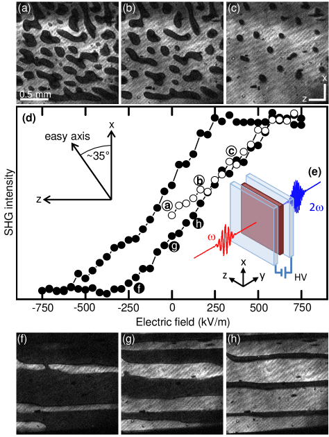
In stark contrast to the bubble topology the re-emergence of the opposite domain state during gradual reversal of the poling field leads to the formation of domains that appear as stripes along the axis on the surface of the (010) sample, see Figs. 1(f) to 1(h). Nucleation of domains occurs primarily at the sample edges but was also observed within the sample. Note that the direction of the stripes is not that of the spontaneous polarization or of the electric poling field.
As an interpretation, the nucleation of domains in Figs. 1(a) to 1(c) is determined by the emergence of a spin spiral upon crossing . This is an entirely magnetic phenomenon because the primary order parameter is magnetic and electric fields are not involved. In contrast, the domain structure in Figs. 1(f) to 1(h) results from the modification of a spin spiral that is already present. This modification is based on magnetoelectric interactions because it is driven by the electric field. Note that the weakest magnetic exchange is found along the direction.tian09 This explains the formation of the domain stripes along z on the (010) face.
III.2 Dynamic switching of domains
Figure 2 shows the dynamic switching of magnetic helicity domains in MnWO4(010) by an electric field. As mentioned in Section II.3 the fastest time in which the electric field can be reversed is 50 ns. This is determined by the slope of the repetitively applied voltage pulses. Figure 2(b) reveals that the response of the magnetic order parameter to the electric field pulses of kV/m is strikingly slow: The reversal of the magnetic domain state takes as long as 20 ms. The domain structure throughout this dynamic reversal is shown in Figs. 2(d) to 2(f). It differs substantially from the one in zero-field-cooled samples and also from the one obtained during quasi-static field reversal (Fig. 1). The dynamic reversal leads to the nucleation of rhomboid-shaped domains whose sides run approximately parallel to the axis and the magnetic easy axis. In this nonequilibrium state, a tendency to minimize the domain surface is already present in the form of rounded corners (arrow in Fig. 2(f)) and domain fusion (arrow in Fig. 2(e)) but much less pronounced than in Fig. 1(c). Although the images are accumulated from about 1000 laser pulses (i.e. 1000 poling cycles) a well-defined domain structure is obtained. Therefore, the domain reversal always progresses through the same domain pattern. This pronounced memory effect is a strong indication for pinning effects.
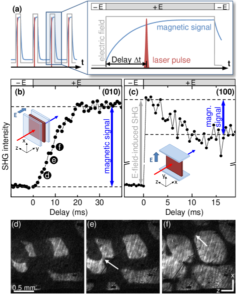
The same type of dynamic switching experiment was also carried out on a MnWO4(100) sample with the result shown in Fig. 2(c). In this geometry the electric field is limited to a maximum value of kV/m because of the larger distance between the electrodes and the limited voltage of the HV source. At the SHG intensity remains constant for an electric field of kV/m. The electric-field reversal to kV/m at leads to a jump of the SHG signal within the rise time of the voltage pulse. This is followed by a gradual decrease of the SHG intensity lasting until ms. At ms, the SHG intensity remains constant at a level that is different from that at . Upon the field reversal from to kV/m (not shown) the SHG intensity returns to its original value.
The jump at is caused by SHG contributions that are induced by the externally applied field but unrelated to the long-range order.meier09a This effect is well-known and documented as “EFISH” (electric-field-induced second harmonic) in the literature.he00 The EFISH signal follows the applied voltage without delay so that its rise time is 50 ns in Fig. 2(c). EFISH contributions are always polarized parallel to the applied electric field which explains their absence in Fig. 2(b) where the light is propagating along the field direction. Only the decrease of the SHG signal from the upper to the lower dashed line in Fig. 2(c) is associated to the actual domain reversal. The reversal changes the domain-related SHG contribution. This changes the interference with the (constant) EFISH contribution and, hence, the net SHG yield until it stabilizes after the domain reversal is completed at ms. The factor of two in switching time between Figs. 2(b) and 2(c) originates from differences in the sample temperature and the applied electric fields, as discussed in detail below.
As mentioned, the (100) sample promotes SHG contributions coupling to the spontaneous polarization.meier10 Any transient decoupling of the polarization from the magnetization would therefore manifest in Fig. 2(c) as a timescale different from that of the magnetization in Fig. 2(b). In particular, a fast response was considered likely for any electronic contributions to the spontaneous polarization.picozzi07 ; lottermoser09 However, no such decoupling is observed. (Remember that the time scale introduced by the jump at is related to the applied electric field and not to a switching of the multiferroic order.) We thus conclude that the magnetic and electric order parameter remain rigidly clamped throughout the switching process so that the polarization, just like the magnetization, reverses on a millisecond time scale. Since faster switching processes are not present it is not necessary to increase the time resolution of the experiment beyond the nanosecond range employed here.
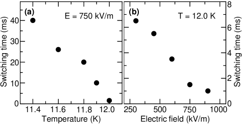
In order to investigate variations of the magnetoelectric domain-reversal time dynamic switching experiments as in Fig. 2(b) we carried out at different temperatures and electric fields. The accessible temperature interval is limited to 0.6 K by the increase of the coercive field towards lower and the decrease of the SHG intensity towards higher temperature. The electric field is determined by the field required to acquire a single-domain state and is limited to 900 kV/m by the breakthrough field in helium gas. Figure 3 shows the reversal time in dependence of these parameters, probed via the magnetic SHG signal on the (010) sample. First, Fig. 3(a) reveals that increases with decreasing temperature. Although a temperature interval of only 0.6 K is investigated changes by a factor of 40, from 1 ms at 12.0 K to 40 ms at 11.4 K in an electric field of 750 kV/m. Figure 3(b) shows a series of experiments at 12.0 K with fields between 300 kV/m (the saturation field at 12.0 K) and 900 kV/m. Clearly, decreases with increasing field. However, due to the limited field range we cannot make a conclusive statement on the validity of Merz’s law merz57 , which describes the field dependence of the switching time in ferroelectrics. It predicts a relation with as activation field.
In Fig. 4 the evolution of two selected domains in a MnWO4(100) sample for a scenario with two field reversals at and at ms is investigated. The area of the domains is shown in dependence of the delay after the first field reversal; the respective electric field is indicated by the bar on top of Fig. 4(a). The timing of the voltage pulses was chosen such that the second field reversal occurs before the first domain reversal has been completed. After the initial voltage reversal at the areas of domains 1 and 2 grow steadily, albeit at different rates. After the second voltage reversal, domain 1 shrinks again, with a small discontinuity right at the voltage reversal. In contrast, domain 2 disappears abruptly, and unrelated to the voltage reversal. Hence, although the magnetoelectric domain switching progresses smoothly according to Fig. 2, Fig. 4 reveals that local deviations from the averaged response are possible. However, these local deviations are not predictable or controllable and they change with each annealing cycle applied to the sample. Note that the collapse of domain 2 shows that the intrinsic speed of domain switching is orders of magnitude faster than the average response of the domains to the electric field. Collapsing domains were observed on the (010) as well as on the (100) face of the sample with collapse times faster than 25 ns, the smallest delay between two images investigated in this experiment.
IV Discussion of the magnetoelectric switching
Summarizing Figs. 1 to 4 we conclude that the reversal of magnetic domains by an electric field is governed by domain wall movements on a timescale in the order of milliseconds and thus a surprisingly slow process. Pronounced memory effects govern the reversal. The topology of the magnetic helicity domains was investigated under three different conditions: (i) emergence of the helix (zero-field cooling through ), and reversal of the existing helix under (ii) equilibrium conditions (quasi-static electric-field-induced reversal) and (iii) non-equilibrium conditions (dynamic reversal).
We now have to compare the switching here observed in a multiferroic with that of ferroelectric or magnetic domain reversal by the adjunct electric or magnetic field, respectively, in non-multiferroics. This will highlight some of the principal differences between the magnetoelectric switching processes in this work and the well-documented switching of, e.g., ferroelectric domains by electric fields. There is no explicit theory on time-resolved magnetoelectric domain reversal so that we take a first qualitative approach here.
Models for the reversal of ferroelectric domains involve nucleation at defects, fast growth along the field direction, and slow growth perpendicular to the electric field. scott00 The “fast forward growth” occurs at the speed of sound and is related to the local charge at the domain walls perpendicular to the spontaneous polarization. In Fig. 4 the forward growth is absent. Domain walls parallel and perpendicular to the poling field propagate at about 1 m/s and, hence, at a speed three orders of magnitude below that of sound. We suggest that this is related to the smallness of the spontaneous polarization in the magnetically-induced ferroelectrics khomskii09 ; toledano09 and the resulting dominance of other mechanisms determining domain-wall propagation. One such mechanism is the coupling of the spontaneous polarization to the spin system, and Fig. 2 revealed that this coupling is rigid. Therefore, the energies competing in the magnetoelectric domain reversal are the electric-field energy and the magnetic anisotropy energy . Here an orders-of-magnitudes estimate reveals which corroborates the inertness of the magnetic system for the electric field acting on it: The electric-field energy is orders of magnitude weaker than the energy barrier separating the states with opposite magnetic helicity.
The resulting magnetoelectric nature of the switching process is reflected by the manifestation of the magnetic easy direction in the dynamic domain structure in Figs. 2(d)-(f) which is much more pronounced than in Fig. 1. Measurement of the electric-field dependence of the domain reversal beyond the saturation field, including a verification of the validity of Merz’s law,merz57 could yield further insight but this is restricted by the low breakthrough voltage of the helium gas cooling the sample.
V Summary and conclusion
In summary, time-resolved SHG experiments on multiferroic MnWO4 crystals revealed that the electric-field-induced reversal of the magnetization in multiferroics with magnetically induced improper ferroelectricity is inherently not ultrafast. On the one hand, rapid reversal is inhibited by the inertness of the magnetic system in the electric field which is expressed by the smallness of the electric-field energy in comparison to the magnetic anisotropy energy. On the other hand, the expectation that fast electronic contributions to the polarization picozzi07 ; lottermoser09 might transiently decouple from the slowly reversing magnetization was not confirmed: According to our experiments the ferroelectric polarization remains rigidly clamped to the magnetization throughout the switching process.
With respect to applications, for magnetoelectrically controlled giant-magnetoresistance sensors ramesh07 the electric-field induced reversal of the magnetic order parameter does not have to be faster than observed here. For these applications Figs. 1 to 4 show that memory effects result in a highly reproducible magnetoelectric switching process. No signs of fatigue were observed in our experiments. High durability may therefore be a major advantage of magnetoelectric devices. In addition, understanding and control of the pinning mechanisms causing the memory effect will be the key for tailoring the magnetically induced ferroelectrics according to technological requirements.
Finally, there is a clear need for a theory modelling the non-equilibrium dynamics of the voltage-induced reversal of magnetic domains in multiferroics like MnWO4. Here our orders-of-magnitude estimate of the energy scales involved in the switching process provides a clue about the approach such a theory might take.
The authors thank N. A. Spaldin for helpful discussions and the DFG (SFB 608) for financial support.
| Sample orientation | SHG component | Order probed | EFISH |
|---|---|---|---|
| (010) | @ 2.21 eV | magnetic | no |
| (100) | @ 2.72 eV | magnetic & electric order | yes |
References
- (1) Email address: manfred.fiebig@mat.ethz.ch
- (2) D. Khomskii, Physics 2, 20 (2009).
- (3) R. E. Newnham J. J. Kramer, W. A. Schulze, and L. E. Cross, J. Appl. Phys. 49, 6088 (1978).
- (4) T. Kimura, T. Goto, H. Shintani, K. Ishizaka, T. Arima, and Y. Tokura, Nature 426, 55 (2003).
- (5) N. Hur, S. Park, P. A. Sharma, J. S. Ahn, S. Guha, and S. W. Cheong, Nature 429, 392 (2004).
- (6) M. Fiebig, V. V. Pavlov, and R. V. Pisarev, J. Opt. Soc. Am. B 22, 96 (2005).
- (7) A. V. Kimel, R. V. Pisarev, F. Bentivegna, and Th. Rasing, Phys. Rev. B 64, 201103(R) (2001)
- (8) M. Matsubara, Y. Kaneko, J.-P. He, H. Okamoto, and Y. Tokura, Phys. Rev. B 79, 140411(R) (2009).
- (9) A. H. Arkenbout, T. T. M. Palstra, T. Siegrist, and T. Kimura, Phys. Rev. B 74, 184431 (2006).
- (10) C. Jia, S. Onoda, N. Nagaosa, and J. H. Han, Phys. Rev. B 76, 144424 (2007).
- (11) T. Kimura, Y. Sekio, H. Nakamura, T. Siegrist and A. P. Ramirez, Nat. Mater. 7, 291 (2008).
- (12) G. Lautenschläger, H. Weitzel, T. Vogt, R. Hock, A. Böhm, M. Bonnet, and H. Fuess, Phys. Rev. B 48, 6087 (1993).
- (13) P. Tolédano, B. Mettout, W. Schranz, G. Krexner, J. Phys.: Condens. Matter 22 065901 (2010).
- (14) The Cartesian system (, , ) is related to the monoclinic crystallographic system (, , with Å, Å, Å, and ) as follows: , , . Note that because of is pointing approximately along . The rotated Cartesian system (, , ) is defined by the incommensurate structure as detailed in Ref. meier10, .
- (15) H. Sagayama, K. Taniguchi, N. Abe, T. H. Arima, M. Soda, M. Matsuura, and K. Hirota, Phys. Rev. B 77, 220407(R) (2008).
- (16) M. Fiebig et al., M. Fiebig, N. P. Duong, T. Satoh, B. B. Van Aken, K. Miyano, Y. Tomioka, and Y. Tokura, J. Phys. D 41, 164005 (2008).
- (17) D. Meier, N. Leo, M. Maringer, T. Lottermoser, M. Fiebig, P. Becker, and L. Bohatý, Phys. Rev. B 80, 224420 (2009).
- (18) K. Taniguchi, N. Abe, T. Takenobu, Y. Iwasa, and T. Arima, Phys. Rev. Lett. 97, 097203 (2006).
- (19) D. Meier, M. Maringer, Th. Lottermoser, P. Becker, L. Bohatý, and M. Fiebig, Phys. Rev. Lett. 102, 107202 (2009).
- (20) D. Meier, N. Leo, G. Yuan, Th. Lottermoser, M. Fiebig, P. Becker and L. Bohatý Phys. Rev. B 82, 155112 (2010).
- (21) T. Finger, D. Senff, K. Schmalzl, W. Schmidt, L. P. Regnault, P. Becker, L. Bohatý and M. Braden, Phys. Rev. B 81, 054430 (2010).
- (22) C. Tian, C. Lee, H. Xiang, Y. Zhang, C. Payen, S. Jobic, and M.-H. Whangbo, Phys. Rev. B 80, 104426 (2009).
- (23) G. S. He and S. H. Liu, Physics of Nonlinear Optics, (World Scientific, Singapore, 2000).
- (24) S. Picozzi, K. Yamauchi, B. Sanyal, I.A. Sergienko, and E. Dagotto Phys. Rev. Lett. 99, 227201 (2007).
- (25) Th. Lottermoser, D. Meier, R. V. Pisarev, and M. Fiebig, Phys. Rev. B 80, 100101(R) (2009).
- (26) W. J. Merz, Phys. Rev. 95, 690 (1954).
- (27) J. F. Scott, Ferroelectric Memories, (Springer, Berlin, 2000).
- (28) R. Ramesh and N. A. Spaldin, N. Mater. 6, 21 (2007).