Uniform Conversions of Operating Points and Characteristics of Compressor
Abstract
In the paper, some aspects of the polytropic analysis are developed that concerned with various processes changing the thermodynamic state of flow of a real fluid and with reduction of these processes to processes having a given temperature and pressure of a given real mixture at the inlet. It is shown that all parameters of the process can be converted under condition of full similarity of flow that is formulated in the paper. An operating point of a compressor represents such process. It is to emphasize that parameters of the reduced point include not only volume flow, speed and polytropic head, for which a requirement of similarity of flow at inlet is sufficient, but also polytropic exponent, polytropic efficiency, outlet pressure and outlet temperature. This allows a conversion of all compressor characteristics. A method for that is described.
1 Introduction
In the paper, some aspects of the polytropic analysis are developed that concerned with various processes changing the thermodynamic state of flow of a real fluid and reduction of these processes to processes having a given temperature and pressure of a given real mixture at the inlet. It is shown that all parameters of the process can be converted under condition of full similarity of flow that is formulated in the paper. So dynamic similitude is achieved. Every such conversion is defined after mechanical and thermodynamic properties of both the process to be converted and the given state of mixture at inlet of the reduced process. The conversions are unique, reversible, and they construct a group.
An operating point of a compressor represents such process. Let be given some fixed reference gas composition and reference pressure and temperature. When they are considered at inlet, they are called the reference inlet conditions. Let a compressor operating point has some different gas composition and different inlet pressure and temperature. In many applications and for comparison, the different operating points must be reduced to the reference inlet conditions. In literature and practice before, by the test evaluation, by the conversion of test results to guarantee conditions and comparison with guaranted values, there was considered just well-known fan laws and conditions of similarity of flow at inlet. They allow to convert volume flow, speed and polytropic head from the operating conditions to the reference inlet conditions. However, they are not sufficient to convert the polytropic exponent, polytropic efficiency, outlet pressure and outlet temperature.
In this paper, it is shown that for any compressor operating point, a condition of similarity of flow both at inlet and at outlet defines uniquely a reduced point that corresponds to the reference inlet conditions so that there is dynamic similitude between the operating point and the reduced point. This allows to construct a conversion of all compressor characteristics from one given inlet conditions to another ones. A method for that is described. The results can be generalized achieving dynamic similitude between operating point of the compressor and the reduced point of a geometrically similar machine. The condition of similarity of flow both at inlet and at outlet is named as condition of full similarity of flow. It is to emphasize that parameters of the reduced point include not only volume flow, speed and polytropic head, for which a requirement of similarity of flow at inlet is sufficient, but also polytropic exponent, polytropic efficiency, outlet pressure and outlet temperature.
1.1 Problem
Let us consider an uncooled multistage centrifugal compressor with one suction as inlet and one discharge as outlet without side-flow. We suppose that hydraulic losses in diffusors and between the compressor stages, the dependence of the losses on the gas composition, roughness and Reynolds number, and their influence on performance and characteristics of compressor are treated by a known way e.g. as in [7].
In the polytropic analysis of uncooled centrifugal compressors, J. M. Schultz [4] defined the unique path of compression between two thermodynamic states of gas as a path with the given constant efficiency. This path plays a central role in test evaluation and design of compressors.
Let be given some fixed reference gas composition and reference pressure and temperature. When they are considered at inlet, they are called the reference inlet conditions. Let a compressor operating point has some different gas composition and different inlet pressure and temperature. In many applications and for comparison, the different operating points must be reduced to the reference inlet conditions.
An operating point of the compressor is a point in a set of its parameters such as its inlet and outlet and intermediate parameters including gas composition. So the operating point includes two thermodynamic states of gas, namely states at the inlet and outlet of the compressor, and a path between these states. Its operating inlet conditions, consisting of the operating gas composition and operating gas pressure and temperature at inlet, may be different from the reference ones.
If the operating point undergoes a transformation under the action of certain rules, then the conversion result is called the converted point.
In particularly, if the conversion rules include the reference inlet conditions, then the converted point is called as the reduced point or as the reference point of compressor.
In many applications, it is necessary to reduce any compressor point from its operating conditions to the reference conditions i.e. to convert the operating point of compressor to the reduced point of a similar machine so that similitude is achieved. It means that an operating value of every parameter that has been given, measured or calculated for the operating gas composition and the operating inlet conditions must be converted to its reduced value that corresponds to the reference gas composition and the reference inlet conditions so that there is dynamic similitude between the operating and reduced values.
It is also useful to learn how to convert compressor characteristics given for the reference gas composition and the reference inlet conditions to operating ones and vice versa.
P. 2, 3 contain mostly the well-known terms and approaches used before by guarantee tests and performance monitoring. It is shown that these approaches must be completed.
The fan laws are the result of the conditions of similarity of flow at inlet. They allow to convert volume flow, speed and polytropic head from the operating conditions to the reference conditions [4], [6]. The state of art of test evaluation, conversion of test results to guarantee conditions and comparison with guaranted values is described in [5]. The main objective values of conversion are (i) effective intake volume flow, (ii) pressure ratio, (iii) power at the coupling.
However, the fan laws as well as the results described in [4], [5], [6] are not sufficient to convert polytropic exponent, polytropic efficiency, outlet pressure and outlet temperature. For these purposes, there were attempts to use additional suggestions such as
- invariance of polytropic efficiency,
- a certain rool of proportionality between the operating and reduced isentropic exponents taken for inlet states and the operating and reduced polytropic exponents.
In the paper, it is shown and numerical results are provided that the last two suggestions are inconsistent and contradict each other. None of them lead to dynamic similitude.
In p. 4 – 6 of this paper, it is shown that for any compressor operating point, a suggestion of similarity of flow both at inlet and outlet defines uniquely a reduced point that corresponds to the reference inlet conditions so that there is dynamic similitude between the operating point and the reduced point. This allows to construct a conversion of all compressor characteristics from one given inlet conditions to another ones. The results can be generalized achieving dynamic similitude between operating point of the compressor and reduced point of a geometrically similar machine. The suggestion of similarity of flow both at inlet and outlet is named as suggestion or condition of full similarity of flow. It is to emphasize that this suggestion allows to determine all parameters of reduced point include not only volume flow, speed and polytropic head, for which the requirement of similarity of flow at inlet is sufficient, but also polytropic exponent, polytropic efficiency, outlet pressure and outlet temperature.
1.2 Applications using the coversion problem
The coversion problem above and the condition of full similarity of flow play a role in the following applications working at the following machine configurations:
1. Applications for a single machine:
– Performance Monitoring
– Simulation of operating points
– Characteristics diagnostics, i.e. Determination of actual characteristics of machine
– Model Diagnostics, i.e. Determination of actual parameters of models
– Design
2. Applications for a shop of machines consisting of parallel machines of the same type:
– Simulation of operating points
3. Applications for a station consisting of several machines:
– Simulation of operating points
– Load sharing
– Optimal load sharing and control in real time
4. Applications for a gas network:
– Steady state simulation
– Dynamic simulation
– Load sharing
– Optimal load sharing and optimization of the network state under the various economic and operating objective functions
– Optimal control.
All these applications except for dynamic simulation and optimal control are realized in the systems ACCORD, Graphicord, Compressor-Visualizer and Compressor-Characterizer as their components.
1.3 Specific applications and their implementation
The work grew out from the applications that autor set, defined, carried out or participated. Some of these applications are:
– ACCORD using for steady state simulation, optimal load sharing and optimization of gas networks of any structure;
- Graphicord using for graphical user interface; data base and spread sheet support; scenario management; management of the third party programs; connection with the geographic information system; interface and data exchange with the distributed control systems;.
– Compressor-Visualizer using for performance monitoring and simulation of operating points of compressors, turbines, and other drives;
– Compressor-Characterizer using for performance monitoring, characteristics diagnostics, and model diagnostics of compressors, turbines, and other drives;
– Compass using for performance monitoring, characteristics diagnostics, and simulation of operating points of compressors and turbines.
Historically, ACCORD, Compressor-Visualizer and Compressor- Characterizer were developed at first. Then features mentioned above, which concerned with performance monitoring, simulation and characteristics diagnostics of compressors and turbines, were developed in Compass, Co. Bruel and Kjaer, in collaboration with Co. Wingas Transport additionally to vibrodiagnostics that Compass contained before. From the side of Bruel and Kjaer, the work was carried out by E. Andreassen. Compressor-Visualizer and Compressor- Characterizer were developed by A. I. Gutnikov and author.
The author is glad to thank E. Andreassen, A. I. Gutnikov, A. E. Lapitsky and his colleagues at Wingas Transport for fruitful discussions and cooperation.
2 Basic concepts of compressor tests
2.1 The main parameters of compressor
Let us describe at first a minimal set of parameters allowing a description of the compressor. The Mach and Reynolds numbers are added to the following list of parameters to ensure the use of flow similarity theory.
1. Parameters of the compressor inlet
– – Volumetric flow
– – Pressure
– – Temperature
– – Compressibility factor
– – Isentropic exponent
– – Mach number
– – Reynolds number
2. Parameters of the compressor outlet
– – Volumetric flow
– – Pressure
– – Temperature
– – Compressibility factor
– – Isentropic exponent
– – Mach number
– – Reynolds number
3. Generic compressor parameters
– – Gas composition
– – Volumetric flow at STP (Standard condition for temperature and pressure)
– – Speed of rotation
– – Polytropic head, mass-specific
– – Polytropic exponent
– – Pressure ratio
– – Polytropic efficiency
– – Compressor power, required
2.2 Dimensionless characteristic numbers of compressor used for conditions of similarity of flows of two fluids
Like in [6], pages 35 - 37, we list the following dimensionless characteristic numbers of compressor using as criteria of similarity. Invariance, here – identity, of characteristic numbers means similarity and allows conversion of according parameters from values known for one conditions to values valid for another conditions.
2.2.1 Flow coefficient
| (1) |
where is the tip speed of the impeller and is an impereller cross-section area.
Suppose that the fluid flow does not come off from the wheel or its blades. Then the tip speed is
| (2) |
In multi-stage machines, the flow the tip speed the impereller diameter and cross-section area can be related to the first stage
| (3) |
or to the last stage for the outlet conditions.
2.2.2 Head coefficient i.e. process work coefficient
| (4) |
In multi-stage machines, compression work can be related to the entire compressor while kinetic energy and tip speed can be related to the first stage
| (5) |
or to the last stage for the outlet conditions.
2.2.3 Tip speed Mach number
For multi-stage machines, a tip speed Mach number is
| (6) |
i.e. the tip speed of considering stage divided by the speed of sound as it is in fluid, which has a considering composition and whose state corresponds to specific physical conditions of temperature and pressure,
The speed of sound can be calculated as
| (7) |
| (8) |
We will call the tip speed Mach number as Mach number often for simplicity. So the inlet Mach number is
| (9) |
and the outlet Mach number is
| (10) |
2.2.4 Tip Reynolds number
Tip Reynolds number is
| (11) |
So the inlet Reynolds number is
| (12) |
and the outlet Reynolds number is
| (13) |
where kinematic viscosity is referred to the inlet state of gas at the first stage and is referred to the outlet state of gas at the last stage.
We will consider below just the case of
| (14) |
when the first and last stages have identical rotation speed, e.g. when the stages are located on the same shaft.
2.3 Fan laws
Fan laws relates to the definition of the flow coefficient and the head coefficient The fan laws mean that the volume flow increases linearly with speed and the polytropic head increases quadratically. In the form of tip speed, they means
| (15) |
| (16) |
For the suction volume flow and for the first stage
| (17) |
| (18) |
Conditions of compressor similarity include invariance of the both coefficients of flow and process work. The invariance of the fan laws for two conditions and means that their are the same. The invariance can be considered relative to the speed and in the form of as well as respectively.
For simplicity, we will write instead of where it is not controversial.
3 State of the art: Determination of actual parameters and their partial conversion under laws of similarity of flow at inlet
3.1 Use of equation of state and thermodynamic properties of real gases
Let us suppose that a form of equation of state for real gases is chosen for using in calculations or that tables and diagrams for thermodynamic properties are chosen. So we can assume that we possess the computing functions for all the thermodynamic quantities that are functions of gas composition of thermodynamic state e.g.
| (19) |
| (20) |
| (21) |
| (22) |
The calculations below are valid for any compressor stage and for multi-stage compressor due to use of polytropic path like in [4].
3.2 Actual Performance
From the main parameters of compressor listed above, let be given or measured and On the base of these values, we can calculate the thermodynamic properties at inlet and outlet as follows.
The pressure ratio is
| (23) |
The compressibility factors are calculated due to (20). The polytropic exponent is
| (24) |
With
| (25) |
the polytropic head is
| (26) |
The enthalpies at inlet and outlet are calculated due to (22). Ratio of the polytropic head with the enthalpy rise gives the polytropic efficiency:
| (27) |
A compressor power corresponds to the work expended on the gas during compression. The required compression power in shaft is
| (28) |
3.3 Identity of Mach numbers and flow coefficients at inlet and its using for conversion of operating point
Let be given compositions of 2 fluids and and 2 according inlet conditions and . For these fluids and states, gas properties such as can be calculated and denoted by the corresponding indexes.
For the fluid and inlet conditions let there is given an operating point It means that we know all its data as measured or calculated values such as the inlet flow rate the tip speed the polytropic head the polytropic efficiency the outlet temperature and pressure the required power and so on.
Having point let find now, which parameters can be found for a point that has the reference composition and the reference inlet conditions if we suppose that points and have identical Mach numbers and flow coefficients at inlet of the compressor:
| (29) |
| (30) |
Remember that we consider a compressor constructed so that i.e. the first and last stages have identical rotation speed.
| (31) |
and
| (32) |
With a conversion factor defining as
| (33) |
we get
| (34) |
| (35) |
and the first fan law at inlet that is identity of the flow coefficients
| (36) |
where is taken in the form
These are conditions that concern speed and flow correspondingly and that are like the first fan law.
3.4 Identity of the process work coefficient in the second fan law and its using for conversion of operating point
For conversion of the operating point, we suppose identity of in the second fan law using in the form
| (37) |
Identity of means that
| (39) |
We can conclude that the use of identity of the Mach numbers at inlet (29), the flow coefficients at inlet (30) and the process work coefficients (38) ensures conversion of the inlet flow , the speed and the polytropic process work . Their converted three parameters represent a point in the same space, where a diagramm of compressor characteristics is often given by manufacturer for the reference gas composition and the reference inlet conditions. For any pair of inlet flow and speed, a value of polytropic head can be read from these manufacturer characteristics. The read value is called as expected value. This allows a comparison between the operating value converted to the reference conditions, and the expected value given for these conditions by manufacturer or vendor. No other value can be converted and compared.
4 Full conversion of compressor operating point under suggestion of similarity of flows both at inlet and at outlet
We see that if laws of similarity of flow at inlet are used to conversion of parameters of the compressor operating point and no additional suggestion is used then we lack conversion of outlet temperature and pressure, polytropic exponent, polytropic efficiency, required power and so on. Determination of the reduced outlet state and the reduced polytropic exponent concerns to identification of the reduced polytropic process of the reference gas. We need to find these values so that
| (40) |
where
4.1 The main proposition
There are given i.e. known
1) composition of the reference gas mixture
2) the reference inlet conditions i.e. temperature and pressure at inlet of the reference gas
3) composition components of operating gas mixture
4) operating inlet conditions of operating gas
5) operating outlet conditions of operating gas.
The values 3 - 5 relate to an operating polytropic process of operating gas.
The condition of similarity suggested at inlet includes an invariance of the inlet Mach numbers (29) and the inlet flow coefficients (30). It determines an inlet volume of the reference gas. The third suggested conditions of similarity is an invariance of the process work coefficient (38). It determines a polytropic head of the reference gas.
The outlet conditions of the reference gas are unknown. So the polytropic process of the reference gas is unknown and must be found.
The suggestion that not only the inlet flows of the operating and reference gases are similar but also the outlet flows are similar can be written as
| (41) | |||||
| (42) | |||||
| (43) |
| (44) |
| (45) |
| (46) |
| (47) |
| (48) |
| (49) |
| (50) |
The conditions of invariant Reynolds numbers are not used below because they can be treated by a known way e.g. as in [7]. We do not discuss here, if this way is sufficient.
Proposition 1
The suggestion of similarity of flows both at inlet and at outlet allows conversion of all parameters of the compressor operating point to the reference inlet conditions consisting of the reference gas composition and the reference values of the inlet temperature and pressure so that there is dynamic similitude between the operating and reduced values.
To show how the conversion is constructed we will determine the outlet conditions of the reference gas and the polytropic exponent describing its polytropic path, if we suppose that not only the inlet flows of the operating and reference gas are similar but also their outlet flows are similar.
Remember that we consider below just the cases of
(i) the same uncooled machine;
(ii) when the first and last stages have identical rotation speed e.g. when they located on the same shaft. This case is applied to the same machine.
At inlet, the reference value and the converted value relate to the same value. Therefore and for uniformity, the reference gas its reference inlet temperature and pressure and its thermodynamic properties at inlet will be sometimes below denoted by index instead of
4.2 Effects of similarity of flows both at inlet and at outlet
Similarity of flows both at inlet (29), (30) and at outlet (45), (49) means due to (6, 7, 2, 15, 9, 10 ) that
| (51) |
| (52) |
Because of
| (53) |
| (54) |
we get
| (55) |
| (56) |
4.3 Effect on formulas for polytropic process
For polytropic process
| (57) |
so
| (58) |
Hence, due to definition of as compressibility factor for any equation of state,
| (59) |
Writing these formulas for polytropic process of the operating gas and then for corresponding polytropic process of the reference gas, due to (56)
| (60) |
we get 2 equations
| (61) |
| (62) |
where right sides and are given. With a chosen equation of state for the reference gas mixture, after which compressibility factor can be calculated, we have
| (63) |
So 3 equations (61, 62, 63) for 4 unknown variables and are constructed.
4.4 Effect on formulas for polytropic head
The forth equation follows from the second fan law (39) and the generic formula for the polytropic head (40). From (39), (33), (26, 40)
| (64) |
Here in and in are unknown, all other parameters are given.
4.5 System of equations for the polytropic exponent and the outlet values of temperature, pressure, and compressibility factor
As result, we get a system of 4 equations (61, 62, 63, 64) with where right sides and are given. We like to find
Introducing as the calculated given parameters
| (65) |
4.6 Solution Algorithm
The solution algorithm to the system of equations for the polytropic exponent and the outlet values of temperature, pressure, and compressibility factor consists of the following steps:
1) From (72), find
2) From (69), find
On every step of the algorithm, there are used the solution methods for one-dimensional nonlinear equation.
So finding the polytropic exponent allowed us to find the inlet pressure and temperature. This makes it possible to find the polytropic efficiency by a standard way as follows.
4.7 Calculation of converted value of polytropic efficiency
After the converted outlet state is determined for the reference mixture composition and the reference inlet state , the enthalpies and of the inlet and outlets states can be calculated due to (22). Ratio of the polytropic head with the enthalpy rise gives the polytropic efficiency:
| (74) |
Then the converted required compression power in shaft is
| (75) |
We can conclude that all parameters of the operating point are converted. Every such conversion of the operating point is defined after mechanical and thermodynamic properties of both the process of compression of flow to be converted and the reference state of the reference fluid at the inlet. So, by construction, the conversions of the operating points are unique and reversible. Hence they construct a group.
5 Conversion of compressor characteristics
Let be given any compressor characteristics for any mixture composition and any reference inlet state How can they be converted to another mixture composition and another reference inlet state We show now how to make a point-wise conversion.
Let us consider any compressor point corresponding to the given characteristics as an actual operating point. So we redenote Considering the another mixture composition and another reference inlet state as the reference ones, we redenote Let us implement the condition of full similarity of flow and according procedure described above to any point of the given characteristics. Then we convert the compressor characteristics as necessary.
6 Numerical examples
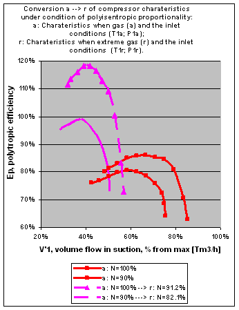
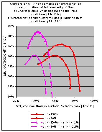
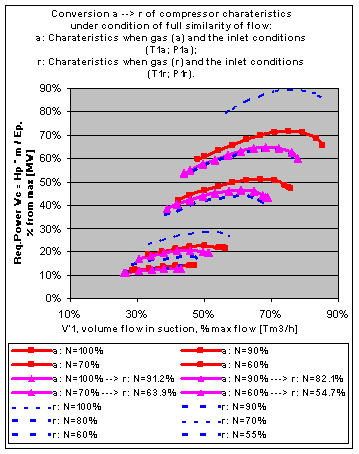
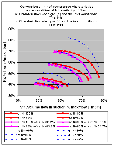
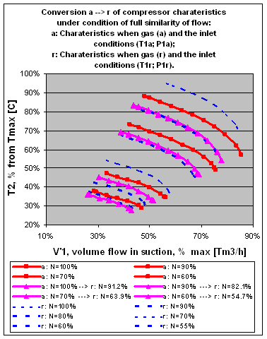
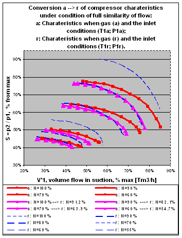
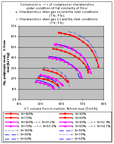
The results of conversion of the compressor characteristics are presented in Fig. 1 – 8 below. In these numerical examples, the thermodynamic properties of real gases and gas mixtures were calculated by the use of Soave-Redlich-Kwong equation of state. We have also performed calculations for all numerical examples using the other equation of state, such as Redlich-Kwong equation of state, Peng-Robinson equation of state, and some others. Qualitatively, the results and figures remain valid.
From data given by vendor as diagramms of characteristics lines in coordinates and we calculated a variety of characteristics of a compressor for 2 gases. One of these gases we used as an actual gas, another one we used as a reference gas. More precisely, we used the second gas composition as a normal case of the reference gas. For the actual gas, the methane content is about 98%. For the normal case of the reference gas, the methane content is about 87%. These characteristics will be called below as the vendor characteristics given (i) for the actual gas and (ii) for the normal case of the reference gas.
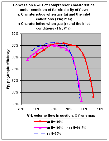
The conversion was made from the actual gas to the reference gas. The actual inlet temperatures and pressures were kept identical to the reference inlet temperature and pressure. Then we can compare the vendor characteristics for the reference gas with the results of conversion. The comparison can be made only for the converted parameters. If the condition of full similarity of flow is used for conversion, then all parameters can be converted and compared. Fig. 3 - 8 show that the comparable parameters and characteristics lie one near another.
Otherwise, if only fan laws and similarity of flow at inlet (29, 30, 38) are used for conversion, then such parameter as the polytropic efficiency cannot be converted and compared. To make comparison possible, some people tried before to use some additional suggestions. One of these is a suggestion that the polytropic efficiency does not change and is invariant to the actual gas and the actual temperature and pressure as well as to the reference gas and the reference temperature and pressure
| (76) |
Another suggestion is that there is a proportionality in some sense between the isentropic exponent at inlet and the polytropic exponent of compression process
| (77) |
We call it as a polyisentropic proportionality.
If the polytropic exponent can be converted then the polytropic efficiency can be converted as well. Indeed, the reduced oultet temperature and pressure can be found after (69, 70, 71). Then the polytropic efficiency can be found after (74).
Suppose, the polytropic exponent is converted under (29), (30), (38) and suggestion of polyisentropic proportionality (77). Let us convert then the polytropic efficiency. Its value contradicts to suggestion (76) and vice versa. Also if the polytropic exponent is converted under suggestion of full similarity of flow then the value of polytropic efficiency contradicts to suggestion (76) and vice versa.
To compare the suggestion of full similarity of flow and the suggestion of polyisentropic proportionality, let us take an extreme case. In the extreme case of the reference gas, the methane content is about 77% due to increase of the isohexan content.
7 Conclusion
We can conclude that the use of identity of Mach numbers at inlet (29), flow coefficients at inlet (30) and process work coefficients (38) ensures conversion of inlet flow , speed and polytropic process work (head) . Their converted three parameters represent a point in the same space, where a diagramm of compressor characteristics is often given by manufacturer for the reference gas composition and the reference inlet conditions. For any pair of inlet flow and speed a value of polytropic head can be read from these manufacturer characteristics. The read value is called as expected value. This allows a comparison between the operating value converted to the reference conditions, and the expected value given for these conditions by manufacturer or vendor.
No other value can be converted and compared, if it is used only identity of Mach numbers at inlet (29), flow coefficients at inlet (30) and process work coefficients (38). The performance monitoring can be constructed only incompletely. Hence its availability and the use is limited.
The use of identity of Mach numbers and flow coefficients at inlet (29), (30), at outlet (45), (49) and process work coefficients (38) ensures conversion of inlet flow, speed, polytropic head, polytropic exponent, outlet temperature, outlet pressure, and polytropic efficiency. This allows a comparison of their operating values converted to the reference conditions with their expected values given for these conditions by manufacturer or vendor. The performance tests, comparison with guarantee values, and performance monitoring can be constructed completely.
Furthermore, the conditions of full similarity of flow (29), (30), (45), (49) and (38) ensures conversion of any compressor point and characteristics from one gas composition taken for one inlet temperature and pressure to another ones. These can be used by such applications as simulation of operating points of compressors and drives; load sharing in multi-machine configurations; load sharing in fluid networks; simulation of fluid networks; optimization of fluid networks; optimal control. Moreover, it simplifies the construction of these applications.
References
- [1] Fermi, Enrico. Thermodynamics, Prentice-Hall, 1936, - 165 p. - Dover edition.
- [2] Feynman, Richard. The Feynman Lectures on Physics, vol. 1
- [3] Roy, Bimalendu Narayan. Fundamentals of classical and statistical thermodynamics , John Wiley & Sons, 2001. - 747 p.
- [4] J.M. Schultz; ”The Polytropic Analysis of Centrifugal Compressors”; Transactions of the ASME, Series A, Journal of Engineering for Power, Vol. 84 (January 1962), pp. 69 - 82.
- [5] VDI 2045 part 1, Acceptance and Performance Tests on Turbo Compressors and Displacement Compressors, Test Procedure and Comparison with Guaranted Values, August 1993
- [6] VDI 2045 part 2, Acceptance and Performance Tests on Turbo Compressors and Displacement Compressors, Theory and Examples, August 1993
- [7] R. A. Strub, L. Bonciani, C. J. Borer, M. V. Casey, S. L. Cole, B.B. Cook, J. Cotzur, H. Simon, M. A. Strite; ”Influence of the Reynolds Number on the Performance of Cenrifugal Compressors”; 1987, ASME J. Turbomach., Vol. 109 (Issue 4, Oct. 1987), pp. 541–544 (ICAAMC)
Notation
Letters
area or cross section,
,
,
speed of sound,
outlet width of impeller,
conversion factor ,
outlet diameter of impeller,
efficiency,
mass-specific enthalpy,
specific polytropic work of compression i.e. specific polytropic head,
isentropic exponent,
mass flow,
Mach number,
gas composition as a list of components,
polytropic exponent i.e. polytropic volume exponent,
speed of rotation, (sometimes
absolute pressure,
specific gas constant,
universal gas constant,
Reynolds number,
pressure ratio,
absolute temperature,
velocity; linear tip speed, referred to of impeller,
velocity,
volume,
volume flow,
power,
specific work of compression i.e. specific head,
compressibility factor,
molar mass,
kinematic viscosity,
density,
flow coefficient,
head coefficient i.e. process work coefficient,
Indexes
inlet
outlet
actual i.e. operating point of compressor
expected value read from manufacturer characteristics
- converted point i.e. result of conversion of operating point of compressor to the reference gas and the reference inlet conditions
standard state i.e. standard condition for temperature and pressure (STP)
polytropic
- the reference gas composition and the reference state i.e. the reference condition for temperature and pressure ()
Figures