Plasmonic interaction of light with negative index and gold nano-checkerboards
Abstract
Negative refractive index materials (NRIM) make possible unique effects such as a convergent flat lens due to the reversed Snell-Descartes laws of refraction. NRIM are also known to be able to support a host of surface plasmon states for both polarizations of light which are responsible for the sub-wavelength image resolution achieved by a slab of NRIM. A generalized lens theorem provides us with a class of spatially varying slab lenses satisfying the prerequisite symmetries to fold the optical space onto itself. This theorem can be derived using powerful tools of transformational optics. A paradigm of such complementary media are checkerboards consisting of alternating cells of positive and negative refractive index that represent a very singular situation in which the local density of modes at the corners are enormously enhanced. We have considered several theoretical and numerical aspects of such structured films including finite slabs of multi-scale checkerboards of NRIM satisfying the generalized lens theorem which are host of strongly enhanced electromagnetic field. Such checkerboards can be mapped using transformational optics onto three-dimensional corner lenses consisting of semi-infinite heterogeneous anisotropic regions of space satisfying the generalized lens theorem. It is also possible to design three-dimensional checkerboards of complementary media, the only restriction being that corresponding unfolded structures in the plane are constrained by the four color theorem. Some of these meta-surfaces in the plane display thin bridges of complementary media, and this further enhances their plasmonic response. Since plasmonic metals mimic the behaviour of NRIM at small length scales, opaque gold films structured at sub-micron scales in a checkerboard fashion were fabricated using focussed-ion-beam technologies and their scattering spectra measured. Sub-wavelength square holes in a thick gold film placed in checkerboard fashion show a broadband extra-ordinary transmission of light. These structures are seen to have enhanced interaction of light at the edges and corners. There is a strong correspondence between the theoretical predictions and the experimental measurements.
In 1967, Veselago proposed a thought experiment in which materials with simultaneously negative permittivity () and magnetic permeability () were shown to have a negative refractive index [1]. A ray analysis allowed him to conclude that a slab of such a negative refractive index material (NRIM) can act as a flat lens that imaged a source on one side to a point on the other. But this result remained an academic curiosity for almost thirty years, until Pendry and co-workers [2, 3] proposed designs of structured materials which would have negative effective and . Further, Pendry also showed that the flat lens proposed by Veselago was very unusual in that the image resolution produced by this lens in principle, did not have any limitation [4]. These so-called meta-materials are indeed structured at sub-wavelength length scales (typically ), hence it is possible to regard them as almost homogeneous. The first experimental realizations were chiefly achieved at GHz frequencies [5, 6], but meta-materials in the near infrared and optical frequencies have been proposed and demonstrated. More recently, new solutions based on geometric transformations to the material parameters and Maxwell’s equations in curvilinear coordinate systems, reported by Greenleaf et al. [8], Pendry et al. [9] and Leonhardt [10], have paved the way towards a markedly enhanced control of electromagnetic waves around arbitrarily sized and shaped solids, leading to electromagnetic invisibility, even in the extreme near field limit [11]. The experimental validation of these theoretical considerations has been given by Schurig et al. [12], who used a cylindrical cloak consisting of concentric arrays of split ring resonators.
However, the touchstone of research in metamaterials remains the quest for the perfect lens: in a seminal paper, Pendry demonstrated that the Veselago slab lens not only involves the propagative waves but also the evanescent near-field components of a source in the image formation [4]. Such a superlensing effect has been demonstrated at optical frequencies through a silver slab film in [14] (resolution of ). It was shown by Pendry and Ramakrishna[15] that the superlensing effect with a slab of negative refractive index medium can be generalized to materials that are anisotropic and spatially inhomogeneous. The only condition is that the system has to respect a mirror anti-symmetry about a plane normal to the imaging axis. Using a geometric technique it was shown [15], as a consequence of this theorem, that two rectangular (semi-infinite) intersecting wedges of NRIM acts as an imaging system whereby a source gets imaged onto itself. This system, originally studied by Notomi [13] using a ray picture, was thus shown to involve the evanescent modes also and act as a unique resonator. Guenneau et al. [19] subsequently generalized this imaging effect to a rectangular checkerboard lattice where alternating cells have positive () and negative () refractive index. It was shown that a source placed in one cell would reproduce itself in every other cell of the infinite lattice. The properties of corners and checkerboards in the presence of dissipation have also been studied using geometric transforms [25, 24]. These transformational optics tools are reminiscent of the work by Leonhardt and Philbin on multi-valued maps for lensing effects via negative refraction [20] which were further investigated in [39]. Monzon et al. [27] recently derived an analytical solution for a finite sized NRIM wedge in the presence of a source. He et al. [28] studied some modes of a resonator with NRIM wedges and constructed an open cavity using triangular wedges of a PC that shows the negative refraction effect (Also see [29]).
In a parallel development in 1998, Ebbesen et al. established that resonant excitation of surface plasmons enhance electric fields at a surface that force light through its tiny holes, giving very high transmission coefficients in the sub-wavelength regime [33]. Pendry, Martin-Moreno and Garcia-Vidal further showed in 2004 that one can manipulate surface plasmon ad libitum via homogenization of structured surfaces [34]. In the same vein, pioneering approaches to invisibility relying upon plasmonic metamaterials have already led to fascinating results [35, 36, 37, 38]. These include plasmonic shells with a suitable out-of-phase polarizability in order to compensate the scattering from the knowledge of the electromagnetic parameters of the object to hide, and external cloaking, whereby a plasmonic resonance cancels the external field at the location of a set of electric dipoles. Recently, Baumeier et al. have demonstrated theoretically and experimentally that it is possible to reduce significantly the scattering of an object by a surface plasmon polariton, when it is surrounded by two concentric rings of point scatterers [38].
It is now well-known that metals that have negative permittivity can mimic the electromagnetic properties of NRIM in the extreme near-field, i.e., when all the length scales in the system are small compared to the wavelength of light [4]. In fact, the imaging by a superlens at optical frequencies was demonstrated through a silver slab film in [14] with a resolution of about .This naturally prompts the question as to whether plasmonic gold and silver nano-films structured as checkerboards can enable control of light and enhance light transmission through the nano-hole apertures while confining light within the transverse plane.
Here we discuss the interaction of light with finite checkerboard structures of NRIM and show that light strongly interacts, namely the corners and the edges. New varieties of checkerboard-like patterns that we call origami lenses are presented. The difficulties of numerically calculating the properties of such checkerboard systems are explained. We have utilized focussed ion beam technologies for fabricating submicron sized metallic structures. A recently developed ion-beam irradiation assisted adhesion technique [41] was used for making structures where only small patterned regions are retained. We demonstrate the power of this technique here in making complex structures such as checkerboards on gold films. Spectral measurements of the fabricated checkerboard structures are presented. From a comparison of the bright and dark field images and spectra of the structures, it is concluded that most of the scattering originates in the edges and corners of the structure. Broadband near-infra-red transmission through sub-wavelength holes in a gold film arranged in checkerboard fashion is demonstrated.
1 Singular electromagnetics of checkerboard structures
1.1 Generalized Lens Theorem: Complementary Media
Some of the properties of checkerboard structures can be deduced by resort to the so-called generalized lens theorem, as illustrated in Fig. 1. The original ‘perfect lens’ presupposed a slab of material with =-1 and = -1, as shown on Fig. 2(a), whereby a source is mirror imaged on the other side of the slab lens. In Fig. 3, we note that such a lens is simply shifting the location of the source plane by a distance , where is the thickness of the lens: a source located on the left interface of the lens produces an image of the right interface. This property is in fact very general and is the cornerstone of any imaging system via complementary media: the image plane is mapped onto the source plane.
However, focussing will occur under more general conditions. Any system for which
will show identical focussing. Focussing will always occur irrespective of the medium in which the lens is embedded. This is true for any medium which is mirror antisymmetric about a plane. Thus, in general, a negatively refracting medium is complementary to an equal thickness of vacuum and optically ’cancels’ its presence.The compensating action extends to both the evanescent as well as the propagating modes. Due to this,there is perfect transmission and the phase change of the transmitted wave is zero. In fact, the most general conditions include anisotropic materials as well [15].
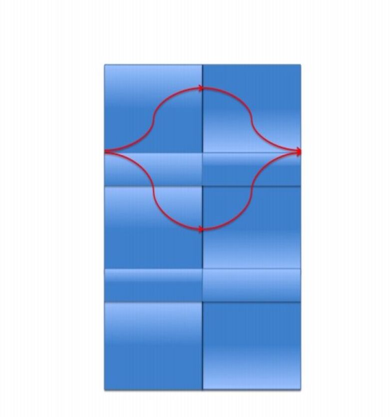
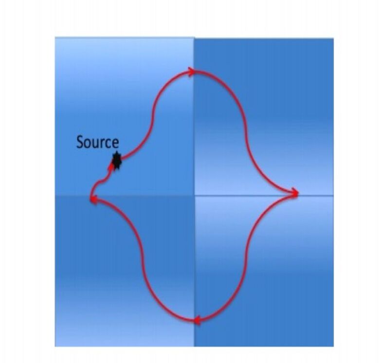
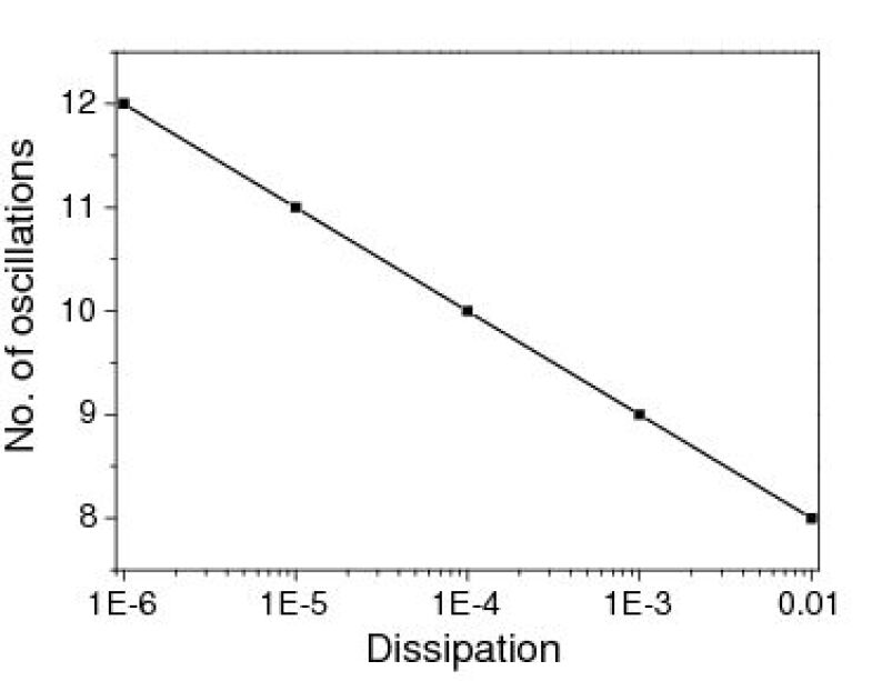
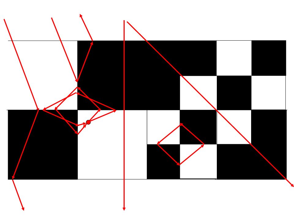
A corner made of a NRIM shares the perfect property of other negatively refracting lenses. This has been shown in [15] using the technique of coordinate transformation. A pair of negatively refracting corners with and is capable of bending light in a loop and forming a series of images such that the light circulates within the loop forever (see Fig. 4). In the electrostatic limit, all the surface plasmon modes in this system are degenerate and the density of states diverges. If we can further divide each region into two regions sharing an interface along the main diagonals so that we now have eight infinite regions, seven perfect images (one in each corner) are formed(see Fig. 5). As in the case of Fig. 4, the light circulates within the loop forever. In Fig. 6, we have plotted the number of plasmon oscillations in the medium as a function of the logarithm of the dissipation in the medium, as expected [25]. The number of oscillations depends inversely upon the logarithm of the dissipation, which is known to affect the resolution of the image formed [16, 17, 18] as per: , where is the thickness of the slab lens and is the dissipation. Clearly, the lower , the larger , which is also in accordance with the fact the lower , the larger the number of spatial oscillations of surface plasmons at the slab interface, see also Fig. 6.
A checkerboard is essentially a collection of periodically placed corners between positive and negative refractive media. The corners and edges are expected dominate all the optical properties of the checkerboards. In infinite non-absorptive checkerboard structures, it has been shown in Ref. [24] that a source placed placed in one cell of the checkerboard produces an image in every other cell. These checkerboard structures retain their image transfer properties irrespective of whether they consist of homogeneous isotropic media or inhomogeneous anisotropic media,as long as they exhibit mirror antisymmetry and adjacent cells are complementary to each other.
All modes are degenerate at a given frequency and the density of modes is infinite. These systems are extremely singular and contain a very large number of corners between positive and negative cells where the density of surface plasmon states diverges. In the absence of dissipation, the infinite lattices of such checkerboard systems are indeed very singular and we can only use the idea of complementary media to deduce anything about the system. Dissipation affects sub-wavelength imaging badly, and the divergence in the local density of states can only worsen the situation.It is due to this fact that the effect of dissipation on sub-wavelength resolution becomes an important issue.
1.2 Contradictions between the ray and the wave pictures
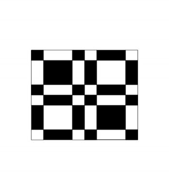
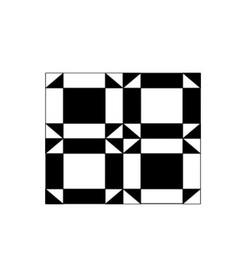
As an example of how checkerboard structures defy conventional logic, consider a checkerboard slab lens of NRIM () with square cells. It is clear from the ray picture in Fig. 7 that the rays incident from the left onto the slab will either emerge on the other side, or will get retro-reflected depending on the initial position and angle of the ray. This suggests that there should be partial transmittance through this lens. The Generalized lens theorem, which is a full wave solution, predicts that every plane wave will transmit through the system without change in amplitude or phase. Full wave numerical solutions also show full transmittance and this actually contradicts the ray picture, as first reported in Ref. [24]. A more singular situation arises in the slab lens of Fig. 8 with triangular checkerboards. The ray picture predicts that every incoming ray should be reflected. However, such a lens also displays full transmission and zero reflectivity, which is thus a form of extraordinary transmission (see also [30] for a similar paradigm). In both cases, the common feature of the slab lens is the equal amount of black and white regions, which is a prerequisite for optical space cancellation [15]. In fact, these are examples of extraordinary transmission mediated by excitation and scattering of surface plasmon waves via the corners. Nevertheless, the mechanism of plasmonic guidance involved here via the interfaces between positive and negative index media differs substantially from the extraordinary transmission through subwavelength holes in thick metallic films experimentally demonstrated in [31].
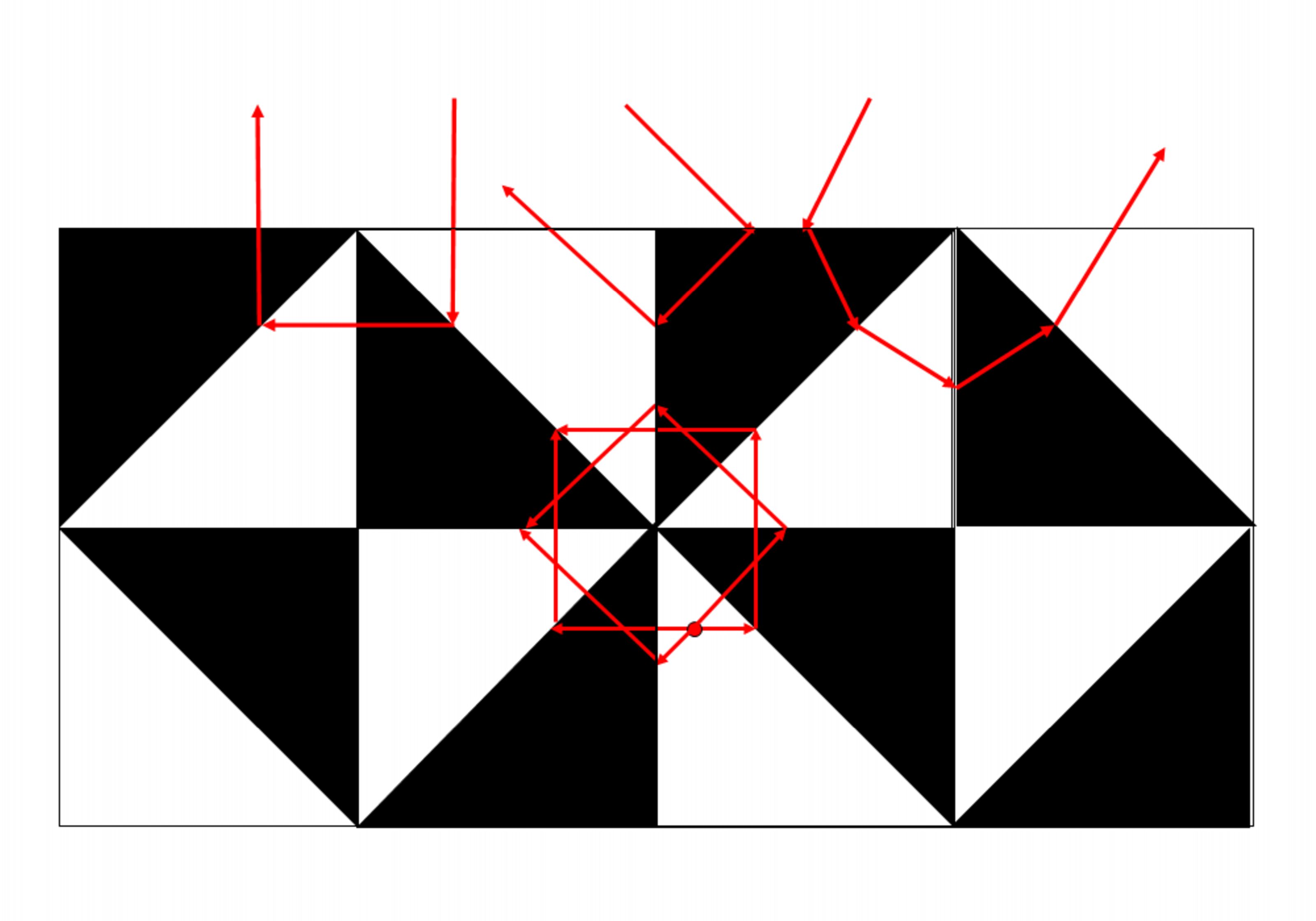
For a finite checkerboard of triangular cells with alternating triangles having refractive index , the ray picture predicts that the rays from a source placed in one of the interior cells cannot escape from the structure if the intersection of the wedges is completely surrounded by other points of intersection. This suggests that such a system will very strongly confine light. Hence the ray analyses suggest very interesting properties for checkerboard systems. However, as illustrated by the paradoxes of the intuitive, but approximate, ray picture showing no transmission and the complementary theorem showing perfect transmission, it becomes imperative to investigate numerically the full wave solutions of finite checkerboard structures of NRIM.
1.3 Origami Lenses
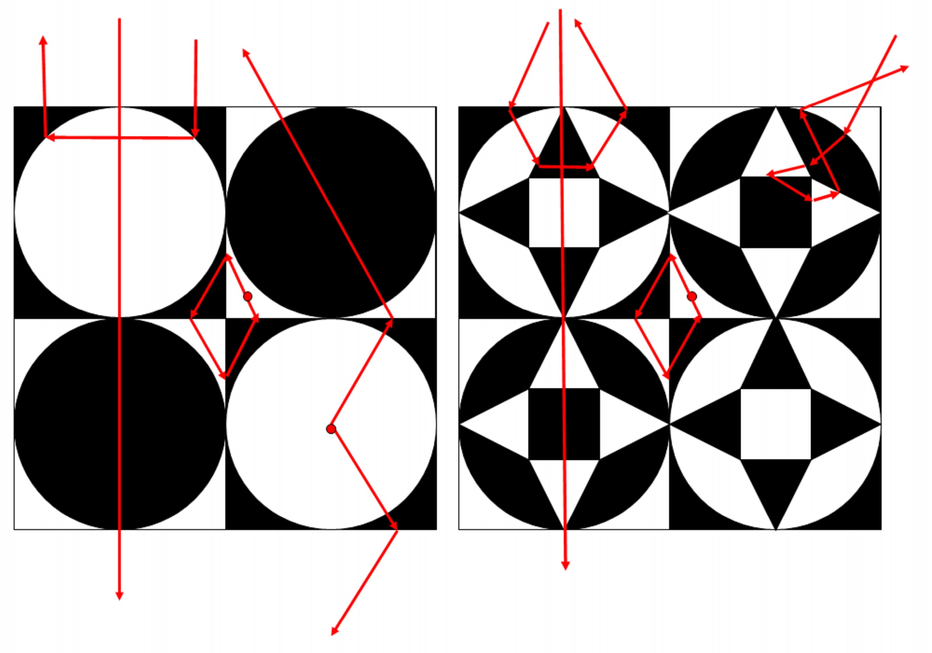
One might look for other ways of tiling the plane. Nevertheless, the crystallographic restriction theorem states that rotational symmetries in planar crystals are limited to two-fold, three-fold, four-fold, and six-fold. Further, keeping a balance between overall positive refractive index material and NRIM implies that we are only left with checkerboards of either rectangular, square or (equilateral) triangular cells. However, the unit cell can have further structure that respects the mirror-antisymmetry conditions as well as the crystallographic conditions. We show examples of structured unit cells in Fig. 10 that have an overall balance of positive and negative complementary media so that the unit cell overall has zero optical pathlength. Such designs are reminescent of Victor Vasarely’s art where checkerboards have been used to great effect [40]. We term such lenses as origami lenses and study them principally due to curiosity. It turns out that such lenses have very interesting electromagnetic properties as we present in the sequel.
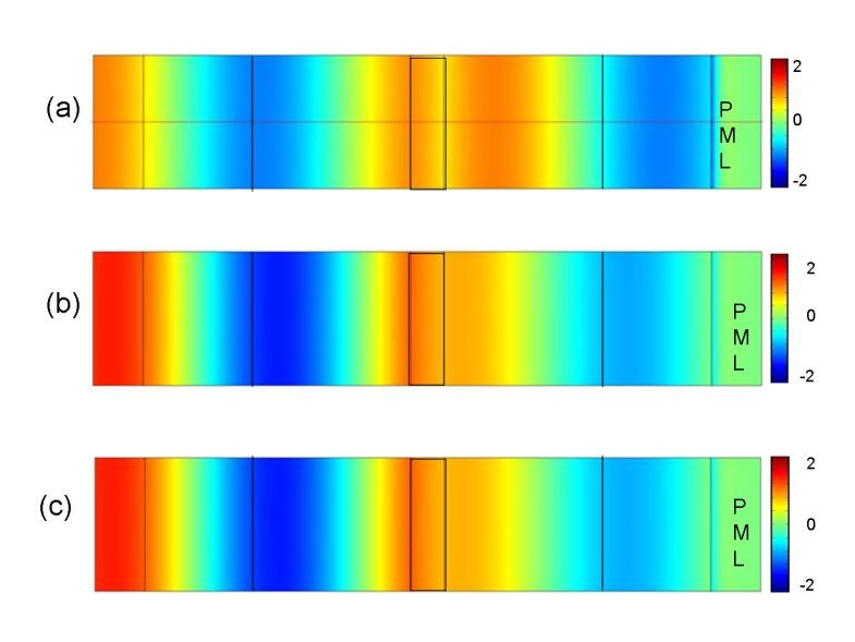
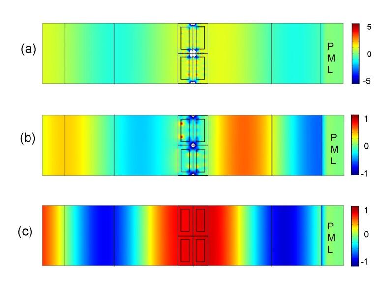
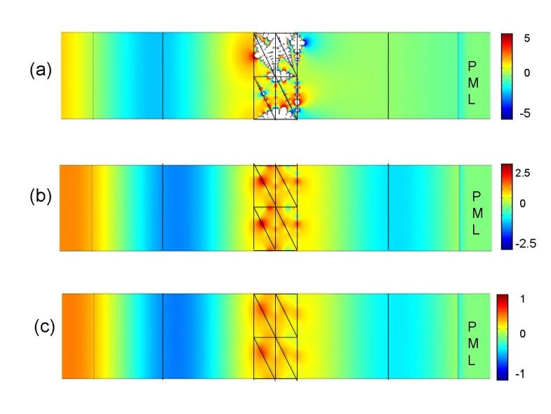
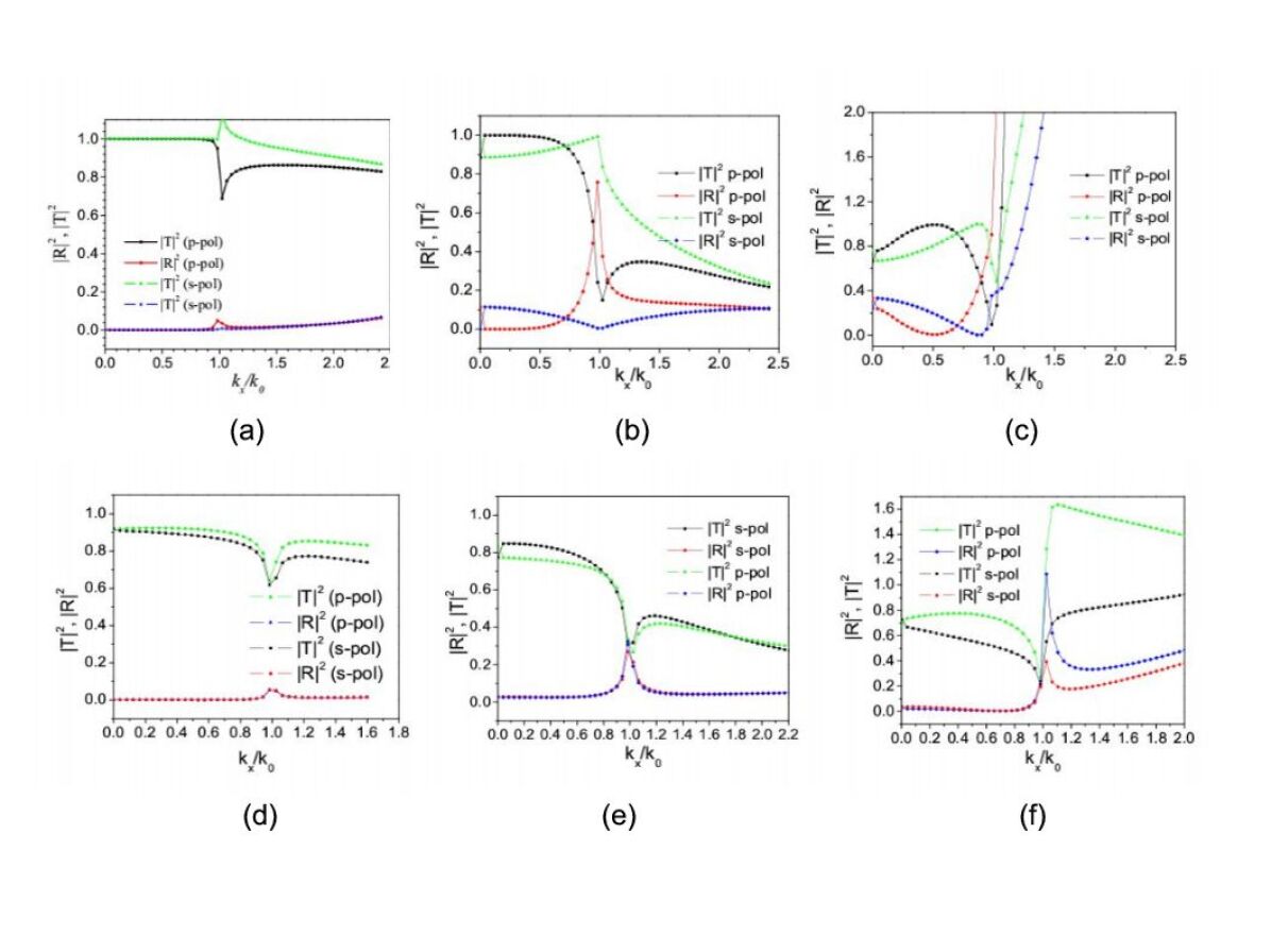
We report in Fig. 11 the finite element computations for a planewave incident on a slab lens of infinite extent along the transverse direction. P-polarized radiation is incident from the left and , the width of the slab, is . In Fig. 11, the transmission properties of three types of slab lens has been illustrated: (a) the perfect slab lens and dissipative slab lenses with (b) and (c) . Perfect transmission is obtained in Fig. 11(a) and this is seen to decrease in Fig. 11(b) and (c). These results have been summarized in Table 1. We then add some complementary media within the slab lens, see Fig. 12-15. We note that while the electromagnetic is clearly enhanced within the origami lenses, the planewave still goes unperturbed as the overall amount of positive and negative index media is well balanced.
.
1.4 Infinite Checkerboards and transformational optics
We have seen that the electromagnetic paradigm of negative refraction is the perfect lens, whereby a homogeneous slab of negative refractive index material maps the image plane onto the source plane, which has been recently revisited through an optical space folding approach [39]. In fact, any heterogeneous anisotropic medium satisfying certain anti-symmetry properties fulfils this optical space folding (leading to a cancelation of the optical path) [15]. It is thus possible to design very complex metamaterials using a very simple group theoretical approach [19], and this already led to the discovery of infinite checkerboards alternating cells of complementary media. However, a systematic study of such checkerboards is far from being easy, as standard numerical packages such as finite elements might fail to converge in the analysis of such strongly resonant metamaterials, as shown in [24]. Some rigorous mathematical study of such sign-shifting media has been performed by the team of Anne-Sophie Bonnet-Bendhia [42]. It is shown there that the Lax-Milgram lemma does not apply anymore (lack of ellipticity), but it is still possible to invoke the Fredholm alternative in order to be assured that any numerical solution found by a finite element algorithm satisfying the prerequisite transmission conditions on the interfaces between complementary media (tangential ‘anti-continuity’ of the field) and adhoc outgoing wave conditions at infinity (such as Sommerfeld ones) exists in its own right (is not spurious). It was also observed in [24] that the PHOTON code is superior to the standard commercial package COMSOL™in handling transmission type problems through rectangular checkerboard lenses with or without dissipation. In the next section, we explore more intricate checkerboard lenses displaying for instance some thin bridges between complementary media within which the electromagnetic field is further enhanced. Some paradoxes occur when the checkerboard lens becomes infinite in all-space dimensions: in this case, one has to think of the periodic structure as being born of a torus and any source located within a unit cell will show an infinite number of images in any other cell of the checkerboard (which actually reduces to one cell).
Transformational optics is a very powerful tool enhancing creative thinking in the context of metamaterials: The first step is to define a map from the curvilinear metric we wish to create (keeping in mind that light will follow the geodesics) onto our usual Euclidean metric (within which geodesics happen to be straight lines).
In the context of generalized lenses, we want to fold the optical space back onto itself, and this leads to negative coefficients within the permittivity and permeability matrices. The coordinate transformation is given by
where d is the thickness of the lens.
This change of co-ordinates is characterized by the Jacobian of the transformation:
| (1) |
The second step is to link the Jacobian of these two metrics to constitutive parameters within the Maxwell system: the curvilinear metric is described by anisotropic heterogeneous permittivity and permeability matrices, while the Euclidean one is associated with identity matrices. Indeed, the inhomogeneous anisotropic metamaterial designed as a result of the co-ordinate transform is described by a transformation matrix (metric tensor) via:
| (2) |
The coordinate transform (1.4)leads to the identity for the transformation matrix outside the lens, whereas inside the lens i.e. for , which flips the sign of , so that the material properties differ from free space only in the direction, whereby the scalar permittivity and the transformed (scalar) permittivity , and similarly for the permeability.
However, in the case of anisotropic and , the transformed medium is now characterized by
| (3) |
which is in accordance with (5).
We note that there is no change in the impedance of the media, since the permittivity and permeability undergo the same geometric transformation: the perfect lens is impedance-matched with its surrounding medium (air, say) so that no reflection will occur at its interfaces.
Altogether, if we consider a complex medium described by general dielectric permittivity and magnetic permeability tensors given by
| (4) |
then the resulting complementary medium is given by
| (5) |
which is the result first derived in [15] and retrieved using group theory (symmetries of Maxwell’s equations) in [19]. The entries in and can also be spatially varying along and . This covers the case of perfect corner reflectors of -fold skew-symmetry and we are therefore ensured of the cancelation of the optical path. It is worth noting that the generalized lens theorem was also applied to infinite checkerboards of skew-symmetry in [19].
1.5 The anisotropic lens
In this section, we present the focussing properties of a single slab lens of anisotropic material. This is a generalization of the anisotropic ‘far-field superlens’ proposed by Shen et. al. in Ref. [21]. The slab lens is impedance-matched to the surrounding medium (vacuum), thus eliminating the possibility of reflection at the interfaces and satisfies the following conditions specified in [21]:
| (6) |
Here, , and are the diagonal components of the permittivity and the permeability tensors (defined to be diagonal matrices.) The subscripts refer to the surrounding medium (vacuum) and the anisotropic slab, respectively. We choose the following general form for a spatially varying permittivity : , and . Fig. 16 illustrates the focussing action of this slab lens. We find that such a slab lens with generalized spatially varying parameters exhibits focussing properties and is thus, a more generalized version of the anisotropic slab lens discussed by Kafesaki et. al.
We have also investigated the dependence of the properties of this generalized slab lens on the dissipation in the slab. The dissipation affects the spatial oscillation of the surface plasmons at the interfaces, in the same manner as described in Section 1.1. This has been illustrated in Fig. 17, where the point source is located on the slab boundary.
1.6 Three dimensional checkerboards of complementary media versus Four Color Theorem
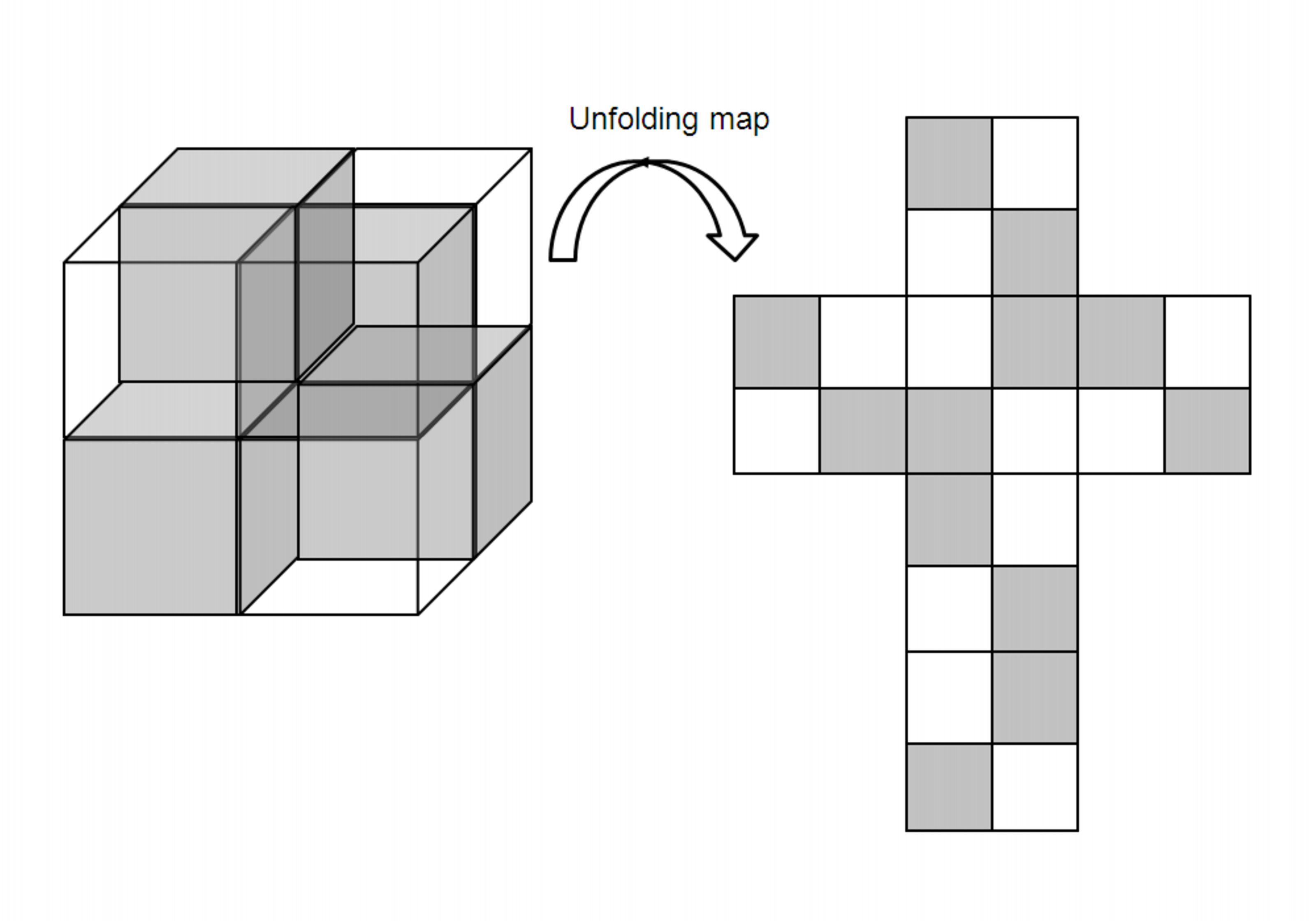
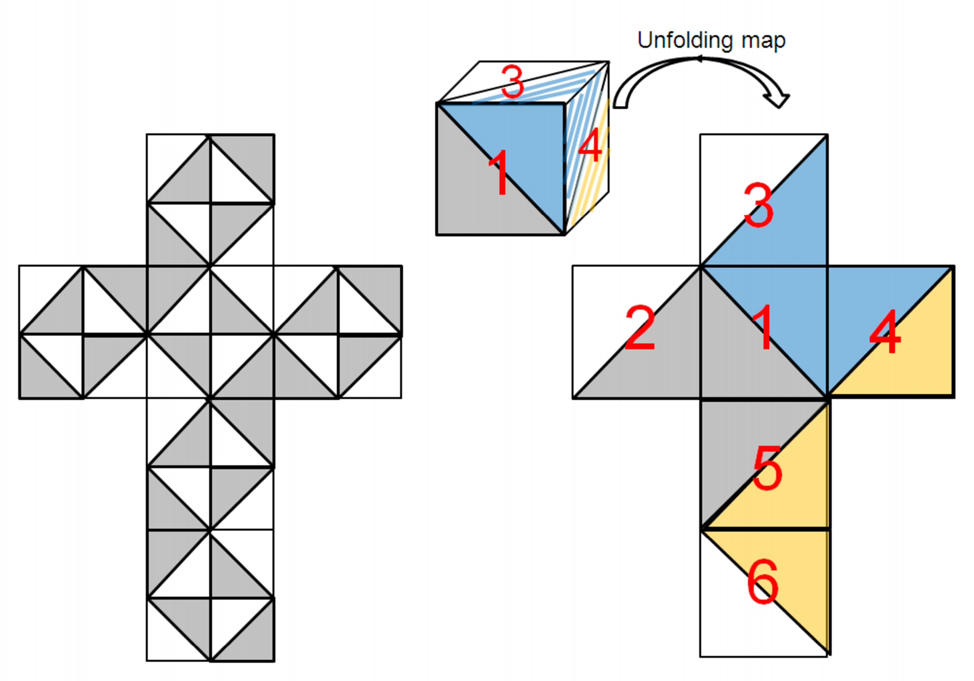
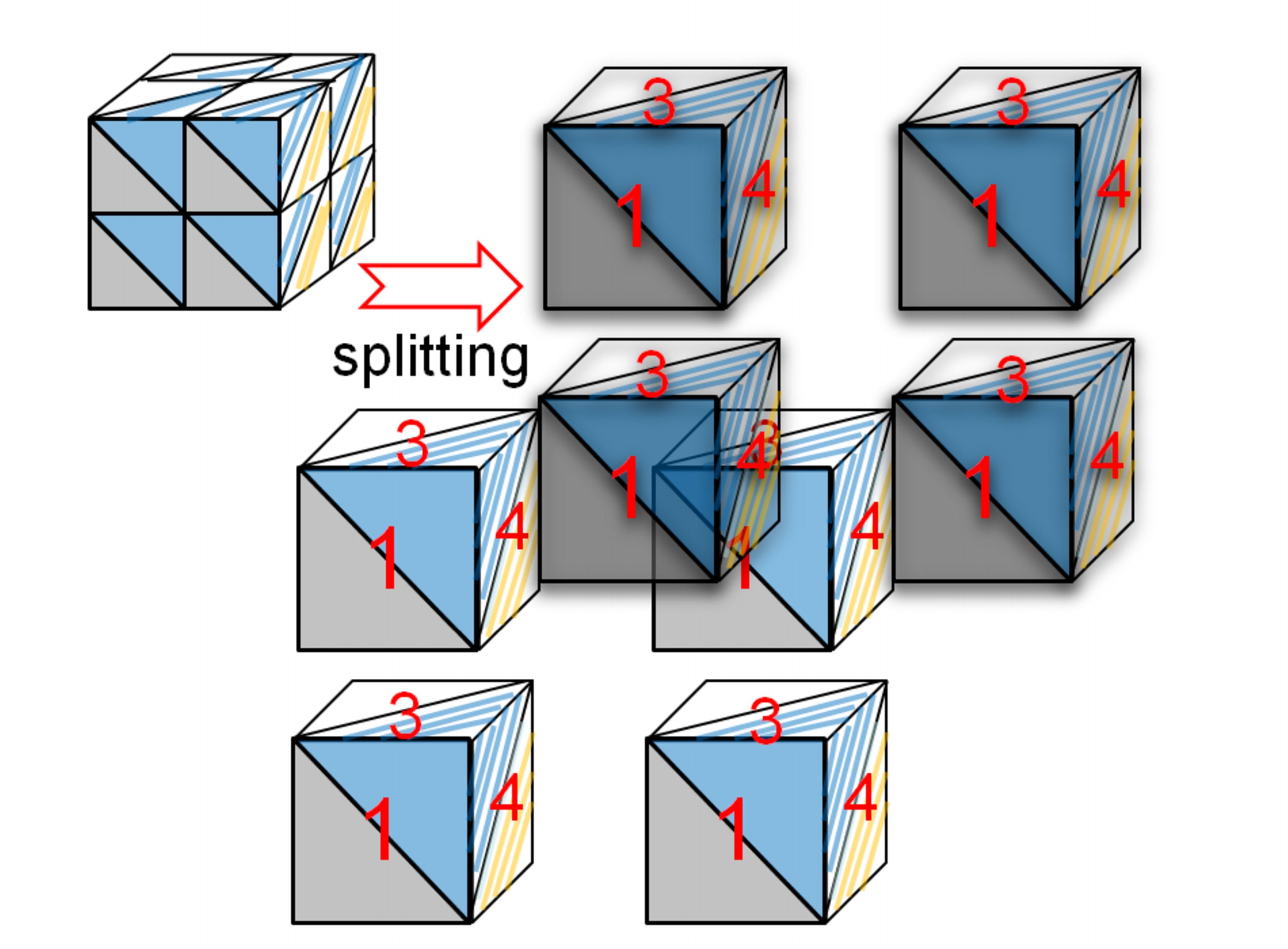
It was shown in Ref. [19] that it is possible to fold the Euclidean space back onto itself using an alternation of positively and negatively refracting cubic regions. We reproduce in Fig. 18 the original idea of Guenneau, Vutha and Ramakrishna. However, these authors did not consider the case of 3D origami checkerboards, such as shown in Figs. 19 and 20: Such checkerboards are more challenging as their design is constrained by the four color theorem.
In mathematics, the famous four color theorem, or the four color map theorem, established in 1976 by Kenneth Appel and Wolfgang Haken [22, 23] using computational techniques, states that:
Theorem Given any separation of a plane into contiguous regions, producing a figure called a map, no more than four colors are required to color the regions of the map so that no two adjacent regions have the same color. Two regions are called adjacent only if they share a border segment, not just a point.
In the present case, this theorem warns us that a two-phase three-dimensional checkerboard with intricated pattern might not be possible at all as its design requires to work with unfolded regions in the plane which should not share frontiers, just like in the four color theorem. We are indeed enable to propose any two-phase checkerboard consisting of right-angled tetrahedra, as shown in Fig. 19 and 20. This is to the best of our knowledge the first example of an impossible three-dimensional checkerboard in the context of plasmonics.
2 Numerical analysis of checkerboard structures
We now examine the response of a NRIM checkerboard lattice lens with finite transverse size, when its unit cells exhibit a four-fold geometry with complex patterns. We note that the case of thin-bridges inclusions within the checkerboard structures represents a singular situation which is very hard to handle with the finite element method.
2.1 Transfer Matrix Method Calculations
The response of some novel checkerboards was calculated using the PHOTON codes based on the Transfer Matrix Method. A schematic representation of such checkerboards has been shown in Fig. 10, extreme left. These calculations are very sensitive to numerical errors. Accurate calculations for such highly singular structures requires a very fine numerical grid. In addition, the regions of opposite index media must have equal thicknesses in order to be optically complementary and satisfy the Generalized Lens theorem. The use of an unsatisfactory numerical grid results in the appearance of numerical artifacts, in the form of resonances at wave vectors , whereas no resonances are predicted to occur. We have dealt with this issue in Ref. [24] and shown that an optimized numerical grid pushes this spurious resonance to . If the thicknesses of the adjacent regions of the checkerboards differs even by a small amount, spurious resonances crop up again. The importance of numerical accuracy has been discussed in Ref. [24]. Similar effects are observed if a less accurate grid (consisting of 202 points) is used or if the adjacent cells of the checkerboard differ by a few nm.
In the upper panel of Fig. 21, we present the result of our transfer matrix calculations for an optimized grid consisting of 262 points along and 106 points along . These media exhibit nearly unit transmittivity and zero reflectivity even for sub-wavelength wave vectors. However, when the embedded regions are very small in size, there appears to be significant deviations from the complementary lens theorem. But this is more likely to be a constraint due to the grid used, rather than implying any actual deviation of the physical behaviour of the system from the complementary behaviour. The transmittivity indicates that the system behaves as predicted by the Generalized Lens theorem. As seen in the earlier cases, the accuracy of the numerical grid is very important. Any small mismatches in the widths of the regions results in the appearance of numerical artifacts. Otherwise, unit transmittivity and zero reflectivity are obtained.
2.2 Finite element analysis of dissipative and non-dissipative finite checkerboards
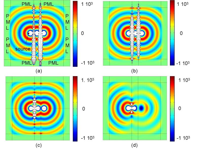
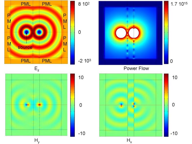
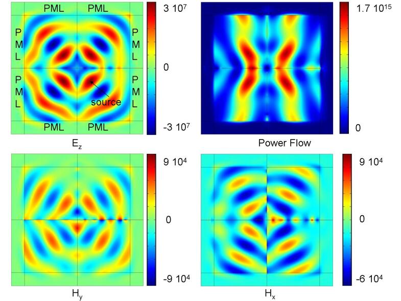
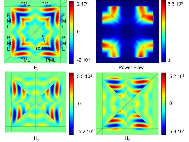
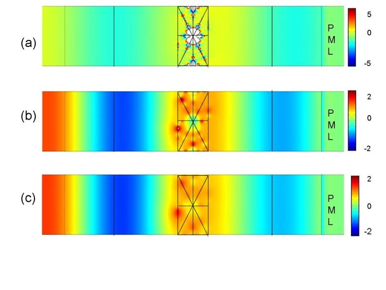
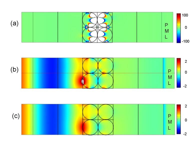
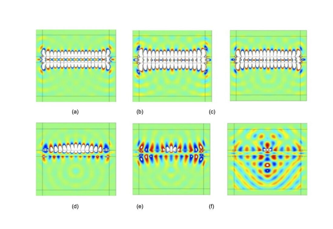
We numerically show in Fig. 12 to Fig. 15 , the response of checkerboard systems consisting of cells alternating air and NRM with increasing dissipation for a planewave incident from the left placed on the checkerboard for the P-polarization. In all these cases studied, the width of the checkerboard . We solve the Maxwell system using Finite Edge Elements (also known as Whitney forms) which naturally fulfill transmission conditions for the tangential components of the electromagnetic field at interfaces between positive and negative index media (hence exhibiting two anti-parallel wave-vectors at both sides of such interfaces). Also, outgoing wave conditions ensuring well-posedness of the problem (existence and uniqueness of the solution) are enforced through implementation of Berenger Perfectly Matched Layers within the rightmost rectangular domain [32]. Moreover, the expression of the incident plane wave is enforced on the leftmost boundary, the field is set to be zero on the rightmost boundary, and periodicity conditions are in order on the top and bottom walls. Two vertical lines located halfway from the checkerboard lens and leftmost and rightmost boundary conditions are used to compute the transmission through the line integration of the value of the scattered field. This leads to the following numerical values (to be compared to transfer matrix results where possible):
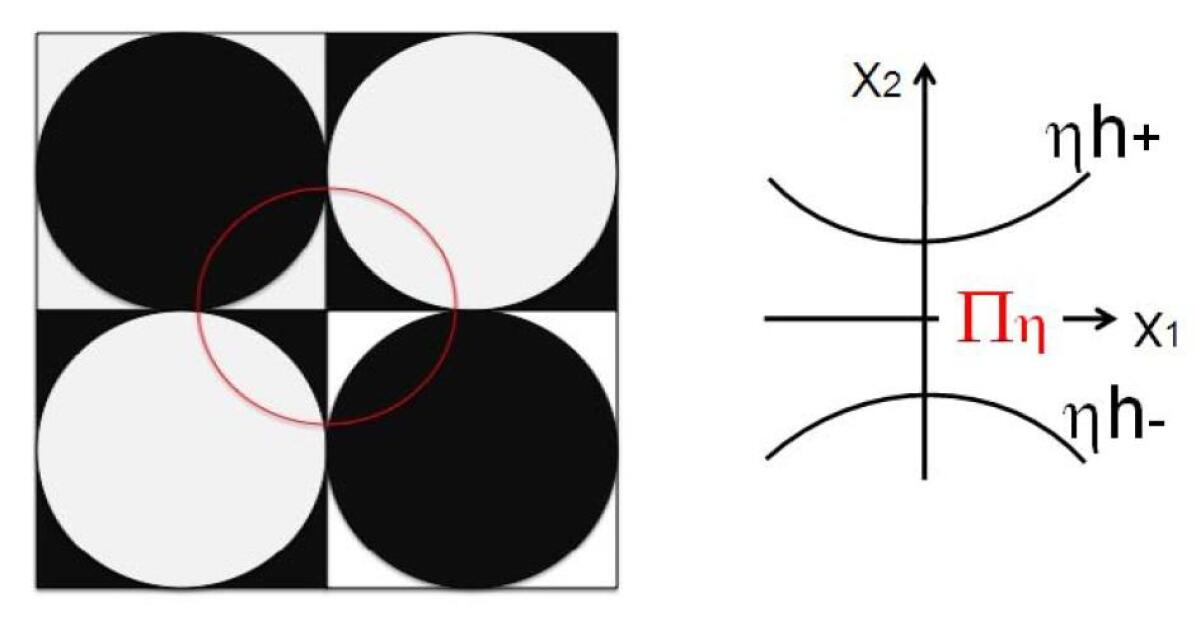
These ones provide a reflectionless interface between the region of interest (a large middle square containing the line source and the silver checkerboard on Fig. 12) and the PML (four elongated rectangles and four small squares) at all incident angles. It is obvious from Figs. 12, 13 that both rectangular and triangular checkerboards enable some imaging process in full contradiction with the ray picture. Extraordinary transmission is at work! There is a large concentration of fields along the interfaces between positive and negative media, which depend upon the symmetry of the systems under consideration. This is exemplified by Figs. 14 and 15. Dissipation is seen to affect these checkerboards, particularly the ones with embedded triangular and circular inclusions. The results obtained for the transmission characteristics of such checkerboards, both the non-dissipative case (with ) as well as dissipative ones with and , have been summarized in Table 1. It is illuminating to interpret the data in this table using either the ray optics or wave viewpoints: the former tells us that 50 % of rays should be transmitted through the rectangular checkerboard lens, whereas all rays should be diffracted for the triangular checkerboard lens; On the contrary, the generalized lens theorem states that any such checkerboard lens has a full transmission in the limit of no dissipation. This wave picture is indeed fully adequate for the ideal case whereby in the NRIM, as exemplified by the first column of Table 1. However, the situation is slightly different when we introduce some dissipation in the NRIM: The transmission hardly exceeds 50 % for rectangular and triangular checkerboard silver lenses, as reported in the last column of Table 1. Interestingly, the case of a checkerboard lens with embedded circles as in Fig. 9 is clearly beyond the scope of the generalized lens theorem: even a small dissipation leads to a dramatic drop in the transmittance, with less than 2 % of light passing through such a silver lens (in contradistinction with the generalized lens theorem, but in agreement with the ray picture). Such a counter-example for the application of the perfect lens theorem to dissipative NRIM should warn us that the behaviour of structured perfect lenses with thin-bridges (within which oscillations of the electromagnetic field are tremendously enhanced) cannot be fully predicted within the frame of the theorem (and moreover numerical simulations should take into account the strongly enhanced non-linear effects). The reason for that is very simple: The interstitial space between the disks can be modelled as a large curved diamond (see Fig. 22) connected to four thin domains see Fig. 22. Assuming that either the electric or magnetic field is orthogonal to the plane, the Maxwell equations reduce to
| (7) |
in each homogenous region (shown in black and white in Fig.) of the Bridge, and the the transmission conditions at the interface between these regions as well as on the upper and lower boundaries and of is given by the continuity of and a negative jump of its normal derivative i.e. and . Assuming the following ansatz for :
| (8) |
where and the rescaled gradient
| (9) |
the Helmholtz equation is reduced to an ordinary differential equation for at the leading order:
| (10) |
This equation is supplied with boundary conditions at the endpoints . Such boundary conditions can be easily derived from the divergence theorem applied to the flux through the interface between each thin bridge and the large region to which they are connected (keeping in mind the sign change across each interface). In the case of constant curvature , that is when (here, thin-bridges are indeed interstitial spaces between circular regions), this leads the following resonant frequency (see eqn. (4.12) in [44]:
| (11) |
Compared to the earlier work in [44], such resonant frequencies are highly degenerate in the present case: in the limit of zero dissipation in NRIM, vanishes and the resonant frequencies form a continuum. This leads to a highly resonant structure at any frequency, which is a hallmark of an infinite local density of states.
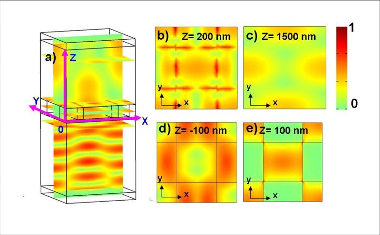
We now turn to the transmission properties of three-dimensional checkerboard structures, see Fig. 25. The generalized perfect lens theorem is still applicable to this configuration, which should then exhibit full transmittance in the limit of zero dissipation. We have modelled such a transversely periodic structure using a three-dimensional unit cell, as depicted in the right panel of Fig. 25, with periodicity conditions on the vertical walls, and perfectly matched layers in the top and bottom layers.
3 Experimental fabrication and measurements
We report here on the experimental fabrication of photonic checkerboard structures on gold films. Uniform gold films 200 nm thick were deposited on polished fused silica substrates using dc sputtering. The resulting films had a surface roughness of about nm measured by atomic force microscopy.A dual beam focused ion beam (FIB) system (FEI NOVA 600) equipped with a field emission a ion source was used to create all the photonic structures presented here. Ion energies of about 30 keV and a beam current of about 10 pA were used for the nanopatterning.
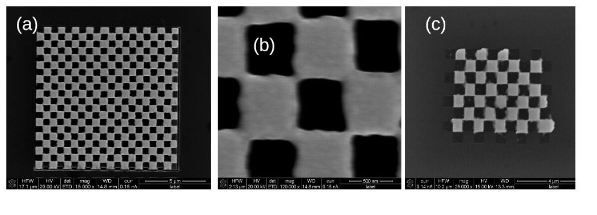
The checkerboards structures were fabricated by direct milling the gold films by the FIB. In order to retain only the checkerboard structures while removing the remainder of the unpatterned gold film, we utilize the technique of focussed ion beam induced adhesion that has been recently developed [41]. The adhesion of a film on a given substrate depends on the nature of the substrate-film interface and surface energies. Gold poorly adheres to silica and usually a thin layer of chromium or titanium is used for proper adhesion. There is no such extra layer in our samples. Irradiation with an ion beam can, however, enhance the adhesion of such a poorly adhering film that has been observed earlier for gallium ions with energies of 10-30 keV. Essentially, the focussed ion beam is used to irradiate the patterned regions that need to be retained where strong adherence is created between the structure and the substrate, then followed by peel-off using adhesive tape that remove the non-irradiated poorly adhering regions of the films. Using the focused ion-beam induced adhesion followed by peel-off, square checkerboard structures were retained for both gold and silver films. The scanning electron microscope pictures of these obtained structures are shown in Fig. 23. It is noted that the peel off technique works well down to checkerboard squares of about 250nm (period of 500nm). However, it has not been possible to make much smaller structures as they get torn during the peel-of process. In fact, the peel off process appears to be more suitable for structuring a softer material like gold rather than silver. Fig. 23(c) shows a small silver checkerboard and should be compared with Fig. 23(a) which shows a similar sized pattern in gold. The tear marks in the silver structure can be clearly discerned. Fig. 23(b) shows a magnified view of the gold checkerboard array showing the connected nature of the checkerboard array that is formed.
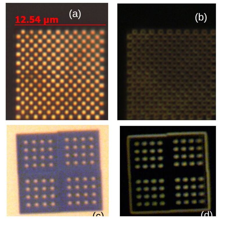
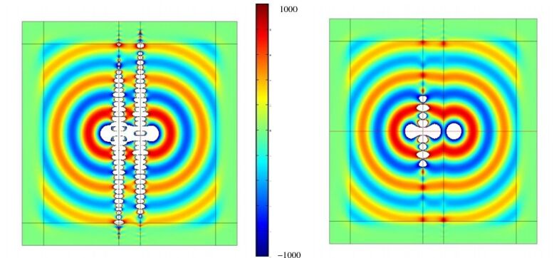
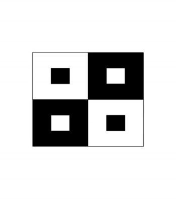
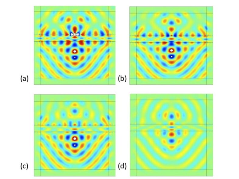
The scattering spectra of the checkerboard arrays were obtained by a Ocean Optics USB 400 spectrometer through a optical fibre connected to the trinocular port of a polarizing microscope (Olympus BX 51). Fig. 24 shows the bright field optical images of the checkerboard structures when viewed with a 100X objective. For the case of the checkerboards, each individual square is separately clearly visible while for the checkerboards, each square is not individually discernible because of the the diffraction limit. Comparatively, the dark field images in Fig. 24 (b) interestingly show only the outlines of the individual squares in the case of the checkerboard array. Essentially, the specular reflection has been cutoff in the dark field images by using light incident at very large angles compared to the bright field images. In Fourier Optics terms, the waves with have been removed by the dark field filter. Thus, from the dark-field images we can conclude that most of the scattering in the checkerboard system occurs at the edges and corners of the system. This underlines our earlier analyses emphasizing the importance of the corners and edges in the system. For comparison, we show in Fig. 26 the simulated fields excited by a line source placed within the checkerboard which shows the electric fields concentrated at the edges and corners of the checkerboard structures. The simulations were performed using the COMSOLTM FEM solver. The bulk of the checkerboard material within the squares hardly has any fields comparatively. In order to cross-check this conclusion that the connected nature of the checkerboard gives rise to the scattering from the edges and corners, an array of unconnected square pads of gold and of the same size ( ) was fabricated. In this case, the entire square elements appear uniformly bright in both the bright field as well as the dark-field images [see Fig. 24 (c) and (d)]. There is no evidence of large scattering from the edges and corners in these unconnected structures.
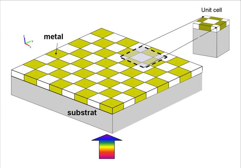
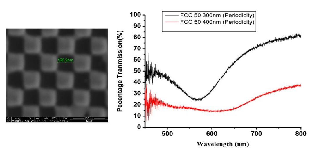
Finally, we measured the extra-ordinary transmission of light through subwavelength square holes ( and ) placed in a checkerboard pattern (of periodicity and ) that were fabricated by direct FIB milling of a 200 nm thick film of gold (shown in Fig. 27). Since the feature sizes are a fraction of the wavelength size at near-infra-red wavelengths, these checkerboards are expected to mimic the action of checkerboards made of negative refractive index materials. The transmission through a checkerboard structure of a given total area was normalized by recording the direct transmission of light through a hole of the same area as the patterned region in the otherwise optically opaque film. These optically thick films with highly subwavelength structures show a broadband extra-ordinary transmittance throughout the red to the near infra-red spectrum (600 nm to 900 nm). Our apparatus does not allow us to measure beyond 900 nm. We must remark here that such large bandwidths are surprising and surmise here that the unique plasmonic properties of the checkerboard structure leads to such properties. Essentially surface plasmon excitations are possible at almost all frequencies below the plasma frequency due to the very large degeneracy of the surface plasmon states in the checkerboard systems. We believe that this degeneracy creates the conditions for the broadband extraordinary transmission in this system.
4 Conclusions
We have presented here an assortment of the surprising photonic and plasmonic properties of checkerboard structures of negative refractive index materials and demonstrated some of the properties in plasmonic checkerboard structures of gold. Checkerboards of media with differing signs of material parameters result in strange landscapes for the plasmons that reside on the interfaces of the system. There can be large concentration of electromagnetic fields (local field enhancements), and large density of modes (large scattering). But within the ambit of the generalized lens theorem, the net sum effect on radiation of two equal sized but complementary media is null. We have verified this result numerically for a variety of complementary checkerboard systems. We have shown that the numerical calculations on checkerboard systems are very vulnerable to numerical artifacts and spurious resonances arise due to finite differencing. Our experiments on plasmonic gold checkerboard structures have shown that most of the scattering appears to arise from the corners and edges of the system. We have also demonstrated a surprisingly broadband extra-ordinary transmission through subwavelength sized checkerboard structured thick gold films.
While some authors consider a slab of NRIM as Alice’s mirror [43], we may say NRIM checkerboards behave in some way like the famous Alice’s Cheshire cat who has the annoying habit of disappearing and appearing at random times and places. “Well, I’ve often seen a cat without a grin”, thought Alice, “but a grin without a cat is the most curious thing I ever saw in my life”.
Acknowledgments
The authors acknowledge funding from the Indo-French Centre for Promotion of Advanced Research, New Delhi under grant no. 3804-02. The contribution of the Inter University Centre, Indore where the gold films used for the study were deposited is acknowledged.
References
References
- [1] Veselago V. G. Usp. Fiz. Nauk., 92, 517 Veselago V. G., Sov. Phys. Usp., 10, 509 (1968)
- [2] Pendry, J.B. and Holden, A.J. and Robbins, D.J. and Stewart, W.J., Phys. Rev. Lett., 76, 4763 (1996)
- [3] Pendry, J.B. and Holden, A.J. and Stewart, W.J. and Youngs, I. IEEE Trans. Micr. Theory and Techniques, 47, 2075 (1999)
- [4] J.B. Pendry, Phys. Rev. Lett. 85, 3966 (2000)
- [5] Smith, D.R., Padilla, W.J., Vier, V.C., Nemat-Nasser, S.C., Schultz, S., Phys. Rev. Lett., 84, 4184 (2000)
- [6] Parazzoli, x., Greegor, C.G. , Li, K., Kontenbah, B.E.C., Tanielan, M.H., Phys. Rev. Lett., 90, 107401 (2003)
- [7] S.A. Ramakrishna, Rep. Prog. Phys., 68, 449 (2005)
- [8] A. Greenleaf, M. Lassas and G. Uhlmann, Math. Res. Lett. 10, 685 (2003).
- [9] J.B. Pendry, D. Schurig, and D.R. Smith, Science 312, 1780 (2006).
- [10] U. Leonhardt, Science 312, 1777 (2006).
- [11] F. Zolla, S. Guenneau, A. Nicolet, and J.B. Pendry, Opt. Lett. 32, 1069 (2007).
- [12] D. Schurig, J.J. Mock, B.J. Justice, S.A. Cummer, J.B. Pendry, A.F. Starr, D.R. Smith, Science 314, 977 (2006).
- [13] Notomi, M., Opt. and Quant. Elec., 34, 133 (2002)
- [14] N. Fang, H. Lee, C. Sun, X. Zhang, Science, 308, 534 (2005)
- [15] J.B. Pendry, S.A. Ramakrishna, J. Phys. Cond. Matter, 15, 6345 (2003)
- [16] R. Merlin, Appl. Phys. Lett. 84, 1290 (2003)
- [17] G. Gomez-Santos, Phys. Rev. Lett., 90, 077401 (2003)
- [18] D. R. Smith, D. Schurig, M. Rosenbluth, S. Schultz, S. A. Ramakrishna and J. B. Pendry Appl. Phys. Lett., 82, 1506 (2003)
- [19] S. Guenneau, A.C. Vutha and S.A. Ramakrishna, New J. Phys., 7, 164 (2005)
- [20] U. Leonhardt and T. Philbin, New J. Phys. 8, 247 (2006)
- [21] Nian-Hai Shen1, Stavroula Foteinopoulou, Maria Kafesaki, Thomas Koschny, Ekmel Ozbay, Eleftherios N. Economou and Costas M. Soukoulis, Phys. Rev. B, 80, 115123 (2009)
- [22] Kenneth Appel, Wolfgang Haken and John Koch, Illinois Journal of Mathematics, 21, 439 (1977),
- [23] Kenneth Appel and Wolfgang Haken, Scientific American, 237, 108 (1977)
- [24] S. Chakrabarti, S. A. Ramakrishna and S. Guenneau, Opt. Express, 14 , 12950 (2006)
- [25] S. Guenneau, B. Gralak and J.B. Pendry, Opt. Lett., 30, 146 (2005)
- [26] D. Maystre and S. Enoch, J. Opt. Soc. Am. A 21, 122-131 (2004)
- [27] C. Monzon, D.W. Forester, P. Loschialpo, Phys. Rev. E, 72, 056606 (2005)
- [28] He, S., Jin, Y., Ruan, Z., Kuang, J., New Jour. Phys., 7, 210 (2005)
- [29] S.A. Ramakrishna, S. Guenneau, S. Enoch, G. Tayeb and B. Gralak, Phys. Rev. A 75, 063830 (2007)
- [30] J.B. Pendry, Contemp. Phys., 45, 191 (2004)
- [31] Martin-Moreno, L., Garcia Vidal, F.J, Lezec, H.J., Pellerin, K.M., Thio, T., Pendry, J.B., Ebbesen, T.W., Phys. Rev. Lett., 86, 1114 (2001)
- [32] J. P. Berenger, J. Comp. Phy., 114, 185 (1994)
- [33] T. W. Ebbesen, H. J. Lezec, H. F. Ghaemi, T. Thio, P. A. Woff, Nature, 391, 667 (1998).
- [34] J.B. Pendry, L. Martin-Moreno and F.J. Garcia-Vidal, Science 305, 847 (2004)
- [35] N.A. Nicorovici, R.C. McPhedran and G.W. Milton, Phys. Rev. B, 49, 8479 (1994).
- [36] A. Alu and N. Engheta, Phys. Rev. E, 72 016623 (2005).
- [37] F.J. Garcia de Abajo, G. Gomez-Santos, L.A. Blanco, A.G. Borisov and S.V. Shabanov, Phys. Rev. Lett., 95 067403 (2005).
- [38] B. Baumeier, T.A. Leskova and A.A. Maradudin, Phys. Rev. Lett., 103, 246809 (2009).
- [39] S. Guenneau and S.A. Ramakrishna, Comptes Rendus Physique, 10, 352 (2009).
- [40] Some of the paintings can be found on the official webpage of Victor Vasarely, http://www.vasarely.com
- [41] N. Shukla, S. K. Tripathi, M. Sarkar, N.S. Rajput and V.N. Kulkarni, Nucl. Instrum. Meth. Phys. Res. B, 267, 1376 (2009).
- [42] A.S.Bonnet-BenDhia, P. Ciarlet, C.M. Zwolf, J. Comput. Appl. Math., 234, 1912 (2010)
- [43] Lewis Carroll, Alice in Wonderland in (The Complete, Fully Illustrated Works. New York: Gramercy Books, 1995: ISBN 0-517-10027-4.)
- [44] A.B. Movchan, N.V. Movchan, S. Guenneau and R.C. McPhedran, Proc. Roy. Soc. Lond. A, 463, 1045 (2007)