Micromegas for imaging hadronic calorimetry
Abstract
The recent progress in R&D of the Micromegas detectors for hadronic calorimetry including new engineering-technical solutions, electronics development, and accompanying simulation studies with emphasis on the comparison of the physics performance of the analog and digital readout is described. The developed prototypes are with 2 bit digital readout to exploit the Micromegas proportional mode and thus improve the calorimeter linearity. In addition, measurements of detection efficiency, hit multiplicity, and energy shower profiles obtained during the exposure of small size prototypes to radioactive source quanta, cosmic particles and accelerator beams are reported. Eventually, the status of a large scale chamber ( m2) are also presented with prospective towards the construction of a 1 m3 digital calorimeter consisting of 40 such chambers.
1 Introduction
Calorimetry for experiments at a future collider will use Particle Flow [1] as a base technique for the physics event reconstruction. By this approach a jet energy resolution lower than 3.8% for 40 – 400 GeV jets can be reached and thus the accurate separation of and hadronic decays will be possible. For optimal performance of this technique, calorimeters with very fine lateral and longitudinal segmentation must be employed. One of the proposed technology is a Micromegas (micro-mesh gaseous structure) detector with 1 cm2 pads that are readout by embedded digital electronics processing only 1 or 2 bit information per channel. This concept, which is also called digital calorimetry, makes easier the construction of a high granular sampling hadron calorimeter with single shower imaging capability. Feasibility of the concept will be validated by a performance test of a 1 m3 calorimeter prototype consisting of 40 layers, each equipped with 1 m2 large Micromegas chamber, and having about 370,000 readout channels in total. Main outputs of the R&D program towards the construction of this 1 m3 calorimeter prototype are described in what follows.
2 Micromegas basic performance
Several Micromegas chambers have been produced so far by use of the bulk Micromegas technique [2]. Their size varies from cm2 up to cm2. Each chamber consists of a PCB with top conductive layer segmented into 1 cm2 anode pads, woven mesh supported by insulating pillars 128 m above the anode plane, 3 mm thick plastic frame which defines the drift region, and 2 mm thick grounded steel cover with a drift copper electrode glued on its internal side. Gas distribution is provided by two holes for input and output in the plastic frame. A detailed description of the prototype design can be found elsewhere [3].
The first prototypes have been equipped with an analog readout which was intended mainly for chamber characterization and definition of necessary parameters for future prototypes with digital readout chips embedded on the external side of the chamber PCB. Three 64-channel ASICs providing digital readout were designed: HARDROC [4], DIRAC [5], and MICROROC [6]. They can operate in a power pulsing mode which is intended for matching the ILC beam time structure and therefore to reduce the power consumption down to 10 W/channel. The first two chips have been already used for prototype readout and their performance has been evaluated during test beam campaigns. A design of the last chip, which will equip future chambers, has been completed and its production has just started.
2.1 Prototype characterization using 55Fe X-rays
Fundamental characteristics of the prototype chambers, such as energy resolution, electron collection efficiency, gas gain and signal dependency on the environmental conditions, were measured at laboratory by use of an 55Fe X-ray source. The measurements were performed in Ar/iC4H10 (95/5) and Ar/CO2 (80/20) gas mixtures and the signals from X-rays were processed by the analog readout.
The energy resolution of the chamber was measured to be 7.5 % at 5.9 keV which corresponds to a FWHM of 17.6 %. The maximum electron collection efficiency is reached for an optimal ratio between amplification and drift electric field. It was measured that the maximum of the signal is obtained for the field ratio about 150–200 for both gas mixtures. At this field ratio, the collection efficiency should be maximum. A maximum gas gain of and has been achieved in Ar/iC4H10 (95/5) and Ar/CO2 (80/20) gas mixtures, respectively. In addition, the gas gain depends strongly on the amplification gap thickness. It is estimated from test beam data analysis that gap size irregularities are smaller than 3 m r.m.s.. Finally, the sensitivity of the gas gain to the ambient variables were measured and quantified as %/K-1 and %/mbar-1 for temperature and atmospheric pressure, respectively. These values correspond well to ones predicted from a gas gain model [7].
2.2 Prototype test in particle beams
During the last years the chambers prototypes were tested in particle beams. The major objectives of these experiments were the functional test of new prototypes in real data taking condition and evaluation of the main chamber properties such as gain uniformity, detection efficiency and hit multiplicity, and study of the prototype response in hadronic and electromagnetic showers. The test beams were carried out at CERN PS and SPS lines where chambers were exposed to low momentum electrons of 2 GeV/c and hadrons up to 10 GeV/c as well as to high momentum muons and pions of 200 GeV/c. All measurements were performed in an Ar/iC4H10 (95/5) gas mixture.
2.2.1 Prototype with analog readout
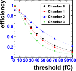
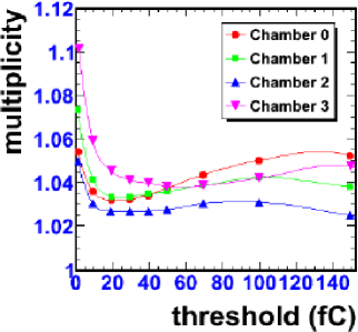
Three chambers with an active area of cm2 and one with cm2, with analog readout were assembled in a stack placed perpendicularly to the beam. An electronics noise of 0.3 fC corresponding to 2000 was measured. The most probable value of the deposited charge is around 22 fC with a variation of 11.3 % over all 672 readout channels. Relatively large dispersion in gain among the channels is mainly due to drift or/and amplification gap non-uniformity. A detection efficiency larger than 97 % was reached at 1.5 fC readout threshold in three of four chambers with an efficiency disparity of less than 1 % per channel. The last one had efficiency around 91 % as a consequence of a higher electronic noise. The efficiency is decreasing with increasing readout threshold as is shown in Fig. 2. The hit multiplicity was measured to be between 1.06 to 1.1 at 1.5 fC readout threshold. Its dependency on the threshold is displayed in Fig. 2, where the raised values of multiplicity above 50 fC are due to the hits from long range -rays.
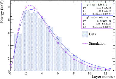
In order to verify that the prototypes also detect multi-hits events, shower profiles have been measured with the cm2 chamber and a variable number of 2 cm thick stainless steel absorber plates placed in front of it. This configuration allows to measure lateral and longitudinal shower profiles and also, by applying a threshold on the recorded charge signals, to compare the deposited energy and number of hits in a chamber. An example of the measured longitudinal shower profile for 2 GeV/c electrons and its comparison with Geant4 Monte Carlo data is shown in Fig. 3 and more details on this study are available in Ref. [8].
2.2.2 Prototype with embedded digital readout
Two stacks with embedded digital readout were assembled and exposed to 2 GeV/c electrons. The first one consists of four chambers with cm2 pads read out by HARDROC chips. A clear image of the beam profile has been seen in each chamber. Because of the short shaping time of the HARDROC chip, only little of the signal can be seen and, consequently, the measured efficiency is about 6 %. The second stack was assembled by four cm2 chambers with DIRAC chips. Unfortunately, due to insufficient spark protection, the life-time of the DIRAC chips in a beam was limited. Nevertheless, an efficiency up to 50% and a hit multiplicity between 1.06 and 1.13 have been measured. These results are affected by low statistics and therefore serve only as a first performance indication. That is why one of the main aim of the next generation readout electronics development is to obtain a reliable spark protection.
3 1 m2 prototype: design and sub-detector test
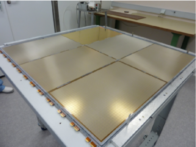
An essential step towards the 1 m3 technological prototype of DHCAL, which will be made of 40 Micromegas chambers with embedded readout electronics interleaved by stainless steel absorbers, is the construction and test of a 1 m2 prototype, the largest Micromegas chamber so far built. The chamber is formed by 6 active sensor units (ASU) of 4832 readout pads of 1 cm2, see Fig. 5. Each ASU is equipped with a mesh and 24 HARDROC readout chips. These ASUs are glued on a 2 mm thick stainless steel supporting plate and the chamber is closed by another 2 mm thick stainless steel plate that carries the cathode. In this arrangement, all the ASUs share the same gas volume. The drift gap is defined by a plastic frame around the chamber and spacers that are placed between the ASUs resulting in very small dead zones of around 1.6 %. The gas distribution is provided by one inlet and outlet in the chamber frame. The readout of two ASUs is chained serially and connected to the data acquisition system by a detector interface board (DIF). The DIF is a mezzanine board which allows to configure HARDROCs by setting readout thresholds and preamplifier gains, to readout the HARDORC data, and also to provide the distribution of the system clock and high voltages through another dedicated board, called inter-DIF, which stands between the DIF and the ASU. The total active area of the complete 1 m2 chamber is 9696 cm2 corresponding to 9216 readout channels. The channel signals are processed by 144 HARDROC chips and three DIF boards. The effective thickness of the chamber, if one does not count the 4 mm of the supporting plates material that can be considered as a part of the calorimeter absorber, is equal to 8 mm and complies well with the ILC specification.
3.1 ASU test and electronics calibration
Prior to the 1 m2 assembly, the electronics characteristics of the readout chips are measured and the overall ASU functioning is verified in a test gas chamber. The electronics tests consist of the determination of the pedestals and noise level of each channel to achieve the lowest detection threshold, and the determination of the channel preamplifier gains.
The determination of the pedestals and noise level is done by measuring the trigger efficiency of each channel as a function of threshold (so-called S-curve). As the threshold is common to all chip channels, it is determined by the S-curve with the highest inflexion point. By changing the preamplifier gain of each chip channels, it is possible to squeeze the S-curves close together and lower the detection threshold to minimum (typically down to 3–4 fC).
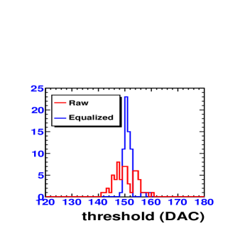
The determination of the channel preamplifier gain is performed by injecting different test charges in the HARDROC circuitry. Once the gain distribution per chip is known, equalization constants are calculated to reduce the spread. The equalization procedure has been validated as shown in Fig. 7 where the S-curve inflexion point distributions for 100 fC test charge with and without equalized gains are plotted.
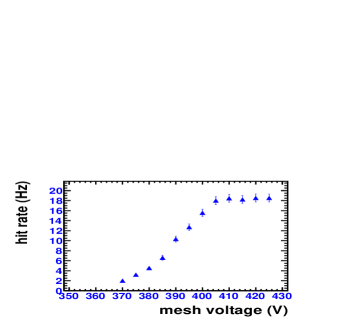
A dedicated gas chamber, which can house one ASU, has been fabricated to perform tests of the ASUs with 55Fe X-rays before they are mounted into the 1 m2 chamber. It has a perforated aluminum cover onto which is glued a cathode foil with a few nm thin conductive deposit on one side. It is therefore transparent to 55Fe quanta which are almost all absorbed in the 3 cm thick drift gap. By collimating the X-ray beam and by measuring the number of hits recorded per unit time on one pad, relative variations of efficiency can be inferred. The impact of the chip settings and detector voltages can be quantified this way. As an example, the strong influence of the mesh voltage (gas gain) on the detection rate is depicted in Fig. 7. Moreover, the box allows to perform the high voltage burn-in in air, which effectively reduces ASU’s sparking rate by washing out the impurities remaining in the amplification gap after the bulk production.
3.2 The of the first 1 m2 in a beam
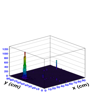
The first 1 m2 prototype has been successfully built and tested in a particle beam in summer this year. This experiment has provided precious information for future mass production. During one month operation in a beam, the functionality of the DAQ system and chamber readout electronics has been verified. Gas gains up to 15.000 has been reached with very few high voltage trips and the first test in a power pulsing mode of the readout electronics has been done successfully. The data taken during this period are currently under analysis. In Fig. 5 is shown a beam profile of 150 GeV/c muons traversing 1 m2 Micromegas prototype which is the first sign of the project feasibility and an important milestone in the large area Micromegas R&D effort.
4 Simulation studies
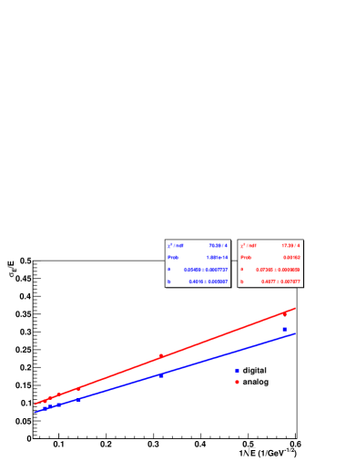
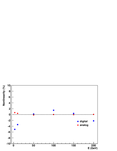
In order to have better understanding of the physics performance of a digital hadron calorimeter with very fine segmentation and its capability to separate hadronic showers, detailed Monte Carlo simulations of a realistic SiD-like calorimeter module [9] have been performed [10]. These studies have been focused on the calorimeter response and linearity, energy resolution, shower profiles, and the impact of the leakage. Results obtained for digital readout with different thresholds were compared against the standard analog readout. Fig.9 depicts the energy resolution for single pions as a function of their energy for analog and digital readout with a readout threshold of 15 fC. Superior energy resolution observed for digital readout is due to the suppression of the Landau and particle path length fluctuations. On the other hand, due to the saturation in calorimeter response, the linearity of a digital calorimeter is not as good as it is in case of analog one, see Fig.9. The saturation effect can be reduced by use of semi-digital readout with two or three thresholds. The determination of the optimal thresholds and their corresponding weights is the subject of current investigation.
5 Conclusions
Several Micromegas chambers have been developed for an application in digital hadron calorimetry. The prototypes with analog readout have been characterized and extensively tested with different particle sources. The tests of these chambers have shown very good performance on detection efficiency and hit multiplicity, the parameters which are crucial for calorimetry at future linear colliders. Based on the obtained results, new generation Micromegas chambers with embedded readout electronics have been designed and produced. The feasibility of the project has been proven by construction and functionality test of the 1 m2 prototype in particle beams. The simulation studies of the digital hadronic calorimeter are well advanced.
6 References
References
- [1] M. A. Thomson, NIM A611 (2009), pp. 25–40
- [2] S. Andriamonje et al., NIM A560 (2006), pp. 405–408
- [3] C. Adloff et al., 2009 JINST 4 P11023, pp. 1–19
- [4] S. Callier et al., TWEPP-09 Proceeding, 2009, pp. 122–126
- [5] C. Adloff et al., TWEPP-09 Proceeding, 2009, pp. 117–121
- [6] R. Gaglione et al., to be published in TWEPP-10 Proceeding, 2010
- [7] C. Adloff et al., Technical Note, LAPP-TECH-2009-03, pp. 1–20
- [8] C. Adloff et al., 2010 JINST 5 P01013, pp. 1–13
- [9] SiD detector, http://silicondetector.org/display/SiD/home
- [10] C. Adloff et al., 2009 JINST 4 P11009, pp. 1–6