Ion Beam Shepherd for Contactless Space Debris Removal
(Accepted for publication. Journal of Guidance, Control and Dynamics. December 2010. Submitted August 2010)
1 Introduction
The steadily increase of the space debris population is threatening the future of space utilization for both commercial and scientific purposes. Since the Sputnik-1 launch in 1957 thousands of satellites have been delivered to orbit with a current launch rate of about 60 new satellites per year. A considerable fraction of the launched mass, almost 6000 tons at the time of writing, has remained in orbit producing more than 15000 trackable objects. In the current situation this number is growing not only because of newly launched satellites but also due to on-orbit explosions and accidental collisions among resident space objects. According to a study by Liou and Johnson [1], even assuming no new satellites were launched, the increase rate of trackable objects generated by accidental collisions would exceed the decrease rate due to atmospheric drag decay starting from about the year 2055. This trend is mostly due to large and massive objects placed in crowded orbits, that is, at altitudes between 800 and 1000 km and near-polar inclination.
It is widely agreed that, in order to reduce this threat, not only newly launched spacecraft and upper stages will need to be deorbited but also a fraction of the existing ones, calling for active debris removal operations (ADR). If these operations do not start soon, a “snowball effects” can take place in which collision-generated objects will generate new collisions leading to an escalation of the number of debris in orbit [1].
The work by Liou and Johnson [1] is significant not only because it analyses the beneficial effects of a planned debris removal campaign but also because it suggests what debris should be targeted first. The preference is put on objects that are more likely to experience collision and to leave a large amount of potential debris mass in orbit: the conclusion is that active debris removal, in order to be effective, should deal with large space debris in crowded orbits up to about 1600 km altitude. By looking at the current US-SSN catalogue one finds that there are more than 1000 objects with mass larger than 1 ton in the LEO environment (i.e. having perigee larger than 2000 km) with a total mass of more than one third of the total catalogued mass in Earth orbit. The great majority of these objects are in quasi-circular highly-inclined orbits. Whatever active removal strategy is chosen, it will clearly need to be able to deorbit an average 2-ton space object in a reasonable amount of time and with a reasonable cost in terms of hardware and fuel. This is especially true if one considers debris removal campaigns in which a few large objects are removed every year and continuously for a few decades[1].
Several active debris removal concepts have been proposed ranging from laser systems ([2], [3]) to electrodynamic tethers ([4],[5],[6]). Solar sails, which are known to be impractical in LEO, have also been proposed for reorbiting dead satellite in GEO ([7]).
Once a quick and effective removal method has been devised there still remains an important technological challenge to overcome: the transmission of momentum from the removal system to the space debris in order to carry out the deorbiting (or reorbiting) maneuver. The most obvious way to do that is to dock the removal system with the target before the deorbiting starts. This operation can, however, be technologically complex and very risky. Space debris are non-cooperative objects generally characterized by a problematic attitude motion (tumbling motion, flat-spin rotation, large amplitude oscillations etc.) which are not easy to dock. Another possible solution is to perform a capture operation with some kind of appendage (e.g. a net or an harpoon) released from the spacecraft. In this case the major difficulty is perhaps connected with the deployment and targeting of the capturing device, which, in addition, would be difficult to reuse for multiple removal operations.
Debris removal concepts based on pulsed-laser ablation systems do offer a key advantage in this regard as they can be operated far from the orbiting target, possibly even from the ground. Unfortunately though, the small impulse obtained from material ablation cannot be effective against targets of size exceeding about 20 centimeters [3].
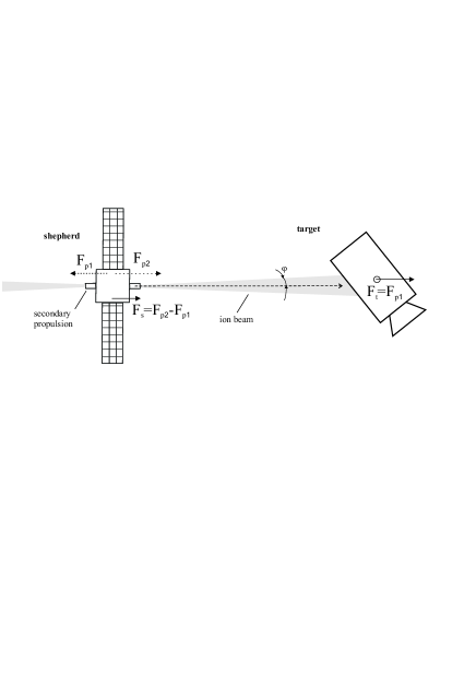
Recently, our team has begun the study of a new space propulsion concept [8] in which a highly collimated, high-velocity ion beam is produced on board a ion beam shepherd spacecraft (IBS) flying in proximity of a target and directed against the target to modify its orbit and/or attitude with no need for docking. The momentum transmitted by the ion beam (ions have been accelerated up to 30 km/s and more on board spacecraft in past missions) is orders of magnitude higher than the one obtained, for equal power cost, using material ablation. Figure 1 describes the idea in one of its most simple implementations. Note that the idea of accelerating a spacecraft with a flux of incident ions was also recently explored by Brown et al. [9] who propose a lunar-based ion-beam generator to remotely propel spacecraft in the Earth-Moon system. Note also that an independent proposal of using a similar system to reorbit GEO debris has been put forward by JAXA[10].
Potentially, the IBS concept can be used for contactless maneuvering of space debris irrespectively of their attitude motion. This article will assess the feasibility of the concept, its expected performance and its main technological challenges. First the main physics of the ion-beam momentum propagation are addressed taking into account the technological level of state of the art ion thrusters. Next, the deorbiting capability for an optimized system applied to orbital debris in circular orbit in LEO is evaluated. Additional issues to be addressed in future studies are outlined and conclusions are drawn.
2 Ion Beam Shepherd Satellite (IBS)
The Ion Beam Shepherd concept (IBS) is schematized in Fig.1. The shepherd satellite is equipped with a primary propulsion system that emits a beam of accelerated quasi-neutral111As it is always the case in electric propulsion technology the plasma leaving the propulsion system is neutralized in order to avoid a net charge to accumulate on the spacecraft plasma and points it towards a target object in order to apply a force on the latter through the momentum carried by the plasma ions. If one neglects the momentum associated with ion-sputtering from the target surface and assuming that the beam fully intercepts the target, will be equal and opposite to the force that the primary propulsion system exerts on the shepherd satellite:
| (1) |
In the real case, secondary ions and neutrals are sputtered back from the surface increasing, in principle, the net momentum transmitted to the target. Yet their ejection velocities are generally small compared to the ones of the impinging ions [11] so that in the end the effect on the transmitted force is negligible. On the other hand, a decrease in the total transmitted momentum occurs when part of the ions miss the target due to ion beam divergence effects and possible beam pointing errors, which sets a constraint on the maximum distance between the IBS and the target as it will be discussed later. Note, finally, that a misalignment between the beam center of pressure and the target center of mass does not affect the net momentum transmitted to the target by the colliding ions as long as the latter continue to fully intercept the target. This is a consequence of the conservation of linear momentum of the system before and after the collision. On the other hand, angular velocity variations do occur in this circumstance and will be dealt with in future studies.
The magnitude of can then be related to the primary propulsion system efficiency , the power and the ion exhaust velocity as:
| (2) |
The same quantity can also be related to the mass flow rate of the propulsion system as:
| (3) |
The shepherd satellite will then need a secondary propulsion system (4) to produce an equilibrium force needed to keep the two satellites at constant distance, as well as a radar or equivalent measurement system (5) to estimate the position of the target spacecraft at all time.
In the hypothesis that the IBS and the target debris are in circular orbit, the magnitude of the force can be computed by setting to zero the second derivative of the distance joining the two spacecraft according to:
| (4) |
where , are, respectively, the mass of the debris shepherd and the mass of the space debris. From the previous equation one obtains:
| (5) |
The maximum distance at which the debris shepherd can be held while the beam fully intercepts the target depends on the size of the latter and on the ion-beam divergence angle as:
| (6) |
where can be thought as the diameter of the largest spherical envelope contained in the space debris volume.
A simple formula to quantify the smallest divergence angle theoretically achievable by an ion thruster can be derived from [12]:
| (7) |
where is the exhaust (longitudinal) velocity of the ions after the acceleration process, is the rms of the transverse velocity of the (maxwellian) ions before being accelerated, their mass, the thermodynamic temperature (measured in electronvolt) of the electrons at the neutralizing cathode (typically 1-5 eV) and is the electron charge. The formula highlights the importance of having high ion ejection velocity (hence high specific impulse) in order to reduce the beam divergence as much as possible. The real divergence will be higher due to the complex mutual and external interaction of the ions, including thermal fluctuations in the plasma source, non-linear forces due to space-charge fields and possible plasma instabilities [12], so that in the end laboratory experiments are required to estimate the real behavior.
High-potential ion thrusters, such as the proposed DS4G [13], are particularly effective in reaching low divergence angles, thanks to their very high ion exhaust velocity and the use of multiple grids. Tests performed by the European Space Agency suggest divergence angles of 2-5 deg [13] which, applied to the present concept, would allow to remotely control a satellite from a distance of about 6 to 14 times its size. A space debris of 2 m diameter, for instance could be controlled with best efficiency at a distance of 12-28 m. More conventional two-grid ion thrusters have a somewhat larger divergence angle (for example, 15 degrees is the suggested value for the NSTAR ion thruster [14]) hence requiring the shepherd to fly much closer to the debris if maximum efficiency is to be reached. Clearly, in order to relax the control requirements and minimize collision risks one could employ a control distance somewhat larger than the one provided by eq. (6) at the price of a small efficiency loss due to the beam only partially hitting the target.
3 IBS Mass Optimization for Constant Thrust
A design optimization of the IBS will now be performed, in which the optimum value of the propellant exhaust velocity is derived in order to minimize the total IBS mass for a debris deorbiting or reorbiting mission. The optimization process is carried out under the following assumptions:
-
1.
The mission begins with the IBS coorbiting with the debris on an initial generic orbit and ends when the two satellites have reached a common target orbit.
-
2.
The thrust provided to the space debris, assumed equal and opposite to the one provided by the primary propulsion system (Eq. (1)), is constant throughout the mission.
-
3.
The primary and secondary propulsion systems employ ion thrusters with the same efficiency () and exhaust velocity ().
In addition, the notation is simplified by setting:
Following the above equalities and using Eqs. (2,3) the propulsion force can be written, for later use as:
| (8) |
from which one deduces that the power provided to each thruster is also constant.
The mass flow rate and power associated with the secondary propulsion system is computed from the equilibrium condition (Eq. (5)) as:
The hypothesis that is now introduced, which is usually reasonable for the case of low-thrust large space debris deorbiting/reorbiting as it will be confirmed later in the article. Following the above hypothesis one obtains:
The total mass of the IBS is made up by the total propellant mass () spent throughout the mission duration , the power system mass () and the structural mass (). Since and are constant the former can be easily computed, with the help of Eq8 as:
| (9) |
Similarly, the power system mass can be computed as:
| (10) |
where denotes the inverse of the specific power (), sometimes called “specific mass”, of the power generation system.
After summing up the three terms and setting to zero the derivative with respect to one obtains the optimum exhaust velocity that minimizes the total IBS mass:
| (11) |
which is the Irving-Stuhlinger222Note that in Stuhlinger book the thruster efficiency is not accounted for in the formula and that the specific power, rather than the inverse if the specific power, is employed characteristic velocity[15]. The corresponding optimum specific impulse is simply with indicating the sea level surface gravity of 9.8.
Finally the optimized total mass of the IBS becomes:
| (12) |
while the spent propellant mass yields:
| (13) |
4 Deorbit Performance
A preliminary assessment of the IBS deorbit performance can be done analytically given the following assumption:
-
1.
The target debris is in a circular orbit
-
2.
The applied deorbit force is constant, fixed by the mission designer, and always directed along the tangent to the orbit
-
3.
During the spiral-transfer the orbit evolves in a quasi-circular manner
The assumption are reasonable given the fact that the great majority of space debris are in almost circular orbits and that the thrust magnitude achievable with high-performance ion thrusters, typically less than 200 , will produce a negligible variation of eccentricity when large debris pieces ( kg) are considered.
For a generic orbit, the time evolution of the orbit semimajor axis under the tangential perturbing force obeys the Gauss equation:
| (14) |
where is the earth gravitational constant, the space debris velocity and the sign - (+) indicates deorbit (reorbit). Under the hypothesis that the orbit evolves while remaining almost circular ( ), Eq. (14) can be replaced by:
| (15) |
Since is constant, Eq. 15 can be integrated to provide the orbit radius evolution in time, which for the case of drag and thrust, respectively, yields:
| (16) |
| (17) |
where and indicate, respectively, the radius at the beginning of the deorbit and reorbit maneuver.
The time duration of the maneuver is obtained by solving Eq. (16) and (17) for after setting and . In both cases the time span obeys:
| (18) |
After substituting Eq. (18) into Eq. (21) one finally obtains the total mass of the optimized IBS system for maneuvering a space debris of mass between circular orbits of radii and with constant tangential low thrust of magnitude :
| (19) |
The propellant mass spent throughout the deorbiting maneuver is computed by substituting Eq.(18) into Eq.(13) to yield:
| (20) |
Finally, the total power needed by the optimized system can be derived from Eq. (8) and taking into account Eqs. (11,18):
| (21) |
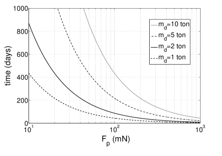
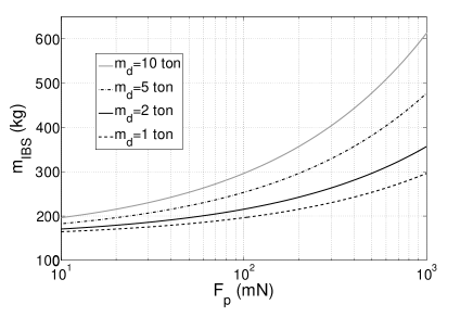
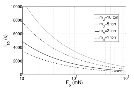
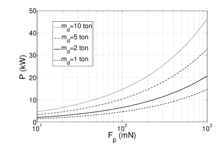
Figures 2 and 3 plot the deorbit time (Eq.(18)) and the optimized IBS mass (Eq. (19)) required to transfer space debris of different sizes from a circular orbit of 1000 km altitude (a high-density debris orbit) to a lower 300-km-altitude circular orbit (below the International Space Station). It can be seen that, for instance, a 100 mN thrust ion thrust with 70% thrust efficiency and employing a power plant with kg/kW is capable of deorbiting a 5-ton debris in less than one year with less than 300 kg total spacecraft mass by employing ion thrusters with an optimized specific impulse s. Note, however, that in order to reduce the beam divergence, allowing a higher control distance between the shepherd and the target debris, a higher specific impulse compared with the mass-optimum value may be desirable resulting in a small increase in total system mass. This kind of design and optimization trade-off, which requires experimental data on thruster plume divergence for different values of the specific impulse, is beyond the scope of the present note.
5 Additional Issues
While the present study has shown that the IBS concept is a promising solution for active debris removal further investigation is needed to address the following issues:
- Ion beam momentum transmission under non-nominal conditions: Analytical and numerical models will be needed to compute the force transmitted to a target once the constraint 7 is not satisfied.
- Proximity formation flying control: The relative dynamics and control of an ion-beam-propelled target space debris need to be investigated.
- Attitude dynamics of the target: As a consequence of the misalignment of the ion-beam center of pressure and target center of mass a net torque originates affecting the target attitude dynamics. While the total linear momentum transmitted to the target, hence the deorbiting efficiency, is not influenced by this effect an excessive spin-up of the target could pose operational risks (e..g centrifugal fragmentation) so that a proper control strategy is likely necessary.
- The flux of secondary ions backscattered from the target surface needs to be estimated in order to address possible risks of contamination of sensitive parts (e.g. solar panels, electronics) of the shepherd satellite.
6 Conclusions
A new concept for active removal of space debris has been presented, in which a space debris shepherd uses the momentum transmitted by a low-divergence accelerated ion beam in order to achieve contactless debris removal. A preliminary analysis of the concept has been conducted highlighting the key aspects of the system design and its performance. Ion thrusters with low beam divergence (< 15 deg), available from current space hardware, are key to allow contactless maneuvering at safe distance from the debris. A design optimization has been conducted in order to minimize the required total mass of the debris shepherd showing that, in the hypothesis that the former is much smaller than the debris mass, optimum specific impulse corresponds to thrust exhaust velocity equal to the Irving-Stuhlinger characteristic velocity. The deorbiting performance for large size (>1 ton) debris has been evaluated analytically in the hypothesis of quasi-circular orbit evolution. As a numerical example, a very large (5 tons) space debris can be deorbited in about 7 months with a total IBS mass of less than 300 kg assuming, as a very preliminary value, a structural mass of 150 kg.
Although the concept implementation appears to be feasible with state of the art space hardware further analysis will be required to investigate the physical interaction between an orbiting body and an ion beam including sputtering phenomena and possible plasma backflow from the debris surface towards the IBS spacecraft. The control of the relative distance between the IBS and the debris flying in proximity for a large time span and the attitude dynamics of the debris will also need to be addressed.
7 Acknowledgments
The work for this paper was supported by the “ARIADNA Call for Ideas on Active Debris Removal”, established by the Advanced Concepts Team of the European Space Agency and by the reserach project “Propagation of Orbits, Advanced Orbital Dynamics and Use of Space Tethers” supported by the Dirección General de Investigación (DGI) of the Spanish Ministry of Education and Science through the contract ESP2007-64068. We would also like to thank the ESA/ESOC Space Debris Office for kindly providing statistical data on actual space debris in LEO.
References
- [1] Liou, J. C. and Johnson, N. L., “A sensitivity study of the effectiveness of active debris removal in LEO,” Acta Astronautica, Vol. 64, No. 2-3, 2009, pp. 236–243.
- [2] Bondarenko, S., Lyagushin, S., and Shifrin, G., “Prospects of Using Lasers and Military Space Technology for Space Debris Removal,” Second European Conference on Space Debris, Vol. 393, 1997, p. 703.
- [3] Phipps, C. R. and Reilly, J. P., “ORION: Clearing near-Earth space debris in two years using a 30-kW repetitively-pulsed laser,” SPIE Proceedings of the International Society for Optical Engineering., 1997, pp. 728–731.
- [4] Bombardelli, C., Herrera, J., Iturri, A., and Pelaez, J., “Space Debris Removal with Bare Electrodynamic Tethers,” Proceeding of the 20th AAS/AIAA Spaceflight Mechanics Meeting, San Diego, California, USA, 2010.
- [5] Sanjurjo-Rivo, M., “Self-Balanced Bare Electrodynamic Tethers. Space Debris Mitigation and other Applications,” PhD thesis, 2009.
- [6] Takeichi, N., “Practical operation strategy for deorbit of an electrodynamic tethered system,” Journal of Spacecraft and Rockets, Vol. 43, No. 6, 2006, pp. 1283–1288.
- [7] Todd, L. and Bowling, T., “Debris Mitigation in Geostationary Earth Orbit,” Paper presented at Dynamics and Control of Systems and Structures in Space (DCSSS), 6th conference, Riomaggiore, Italy, July 2004.
- [8] Bombardelli, C. and Pelaez, J., “Sistema de modificación de la posición y actitud de cuerpos en órbita por medio de satélites guía,” Patent number P201030354. Presented at the Spanish Patent Office on March 11, 2010. PCT Patent Application PCT/ES2011/000011.
- [9] Brown, I., Lane, J., and Youngquist, R., “A lunar-based spacecraft propulsion concept–The ion beam sail,” Acta Astronautica, Vol. 60, No. 10-11, 2007, pp. 834–845.
- [10] Kitamura, S., “Large Space Debris Reorbiter using Ion Beam Irradiation,” 61 st International Astronautical Congress, Prague, Czech Republic, Paper IAC-10.A6.4.8, September 2010.
- [11] J. F. Ziegler, J. P. B. and Ziegler, M. D., SRIM - The Stopping and Range of Ions in Matter, Lulu Press, 2007.
- [12] Reiser, M., Theory and design of charged particle beams, Wiley Series in Beam Physics and Accelerator Technology, 2008, chapter 3.
- [13] Walker, R., Bramanti, C., Sutherland, O., Boswell, R., Charles, C., Fearn, D., Del Amo, J., Frigot, P., and Orlandi, M., “Initial experiments on a dual-stage 4-grid ion thruster for very high specific impulse and power,” AIAA Paper, Vol. 4669, 2006.
- [14] Gardner, B., Katz, I., and Briuza, D., “Predictions of NSTAR charge exchange ions and contamination backflow,” Proceedings of the International Electric Propulsion Conference. Cleveland OH, August 24-28 1997, Vol. 1, pp. 281–289.
- [15] Stuhlinger, E., Ion propulsion for space flight, McGraw-Hill New York, 1964, chapter 4.1.