Co-Designing Multi-Packet Reception, Network Coding, and MAC Using a Simple Predictive Model††thanks: This work is sponsored by the Office of the Secretary of Defense Contract FA8721-05-C-0002. Opinions, interpretations, recommendations, and conclusions are those of the authors and are not necessarily endorsed by the United States Government. Specifically, this work was supported by Information Systems of D,DR&E. Contributions of the Irwin Mark Jacobs and Joan Klein Jacobs Presidential Fellowship have also been critical to the success of this project.
Abstract
We design a cross-layer approach to optimize the joint use of multi-packet reception and network coding, in order to relieve congestion. We construct a model for the behavior of the 802.11 MAC and apply it to several key canonical topology components and their extensions to any number of nodes. The results obtained from this model match the available experimental results, which are for routing and opportunistic network coding, with fidelity. Using this model, we show that fairness allocation by the MAC can seriously impact performance; hence, we devise a new MAC that not only substantially improves throughput relative to the current 802.11 MAC, but also provides fairness to flows of information rather than to nodes. We show that the proper combination of network coding, multi-packet reception, and our new MAC protocol achieves super-additive throughput gains of up to 6.3 times that of routing alone with the use of the standard 802.11 MAC. Finally, we extend the model to analyze the asymptotic behavior of our new MAC as the number of nodes increases.
I Introduction
With the increase in wireless use, current wireless systems are throughput limited and are difficult to scale to large, dense networks. We develop a simple model that is easily extended to analyze the asymptotic regime so that we can evaluate the performance of combining various techniques to increase network throughput and reduce overall delay.
The introduction of network coding [1] led to the proposal of a new forwarding architecture, COPE, for wireless networks. Proposed by Katti et al. [2], COPE identifies coding opportunities and exploits them by forwarding multiple packets in a single transmission. The use of this simple coding scheme was shown to provide up to 3 to 4 times the throughput capacity. Implementing COPE in a 20-node 802.11 test bed, Katti et al. provided empirical data, seen in the upper half of Fig. 1, which shows the benefits of using COPE in wireless mesh networks.
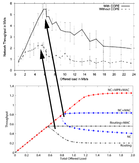
Sengupta et al., [4] and Le et al., [5] provided analyses of these experimental results, but only considered coding a maximum of two packets together at a time or did not address the interaction between network coding and the MAC fairness. As a result, their analyses provide throughput gains that are considerably smaller than the experimental results and do not explain the non-monotonic behavior of the experimental results in Fig. 1. Zhao and Médard, [3], modeled the same experimental results showing that the fairness imposed by the 802.11 MAC explains this non-monotonic behavior. In addition, they demonstrated that the majority of the throughput gain achieved by using COPE is a result of coding three or more uncoded, or native, packets together at time. They showed that these gains are not reflected in three node network models and at least five nodes are required to accurately capture the throughput effects resulting from network coding. The network coding (NC) and routing curves in Fig. 1 show that the results obtained using their model for a simple 5-node cross topology component [3] is consistent with the empirical data from [2]. Furthermore, Seferoglu et. al. [6] used this 5-node topology component, and variants of them, to analyze TCP performance over coded wireless networks. With this in mind, we consider the 5-node cross topology component and additional 5-node topology components, as well as their extensions to any number of nodes, in order to help in our understanding of the effects of combining network coding and MPR in larger networks.
While the performance of COPE significantly increases network throughput [2], it does not completely alleviate the limitation of multi-user interference. With the development of new radio technologies such as OFDMA, the ability to receive multiple packets simultaneously makes it possible to increase throughput and also has the potential to reduce contention among users [7]. Extensive research has been conducted on MPR with uncoded traffic. For instance, the stability of slotted ALOHA with MPR was studied by [8] and several protocols implementing MPR have been proposed by [9] and [10]. However, little analysis has been performed in evaluating schemes involving both MPR and network coding. Garcia-Luna-Aceves et al. [11] compared the use of network coding to MPR, but did not consider the combined use of both MPR and network coding. In addition, Rezaee et al. [12], provided an analysis of the combined use of network coding and MPR in a fully connected network, but did not consider the effects of bottlenecks or multi-hop traffic.
We instead provide an analysis of the combined use of network coding and MPR in a multi-hop, congested network. We extend the initial model proposed by [3] to include various topology configurations, asymptotic behavior, and MPR in order to show that the achievable throughput when using network coding in conjunction with MPR in multi-hop networks is super-additive. We then use this model to design a cross-layer solution to optimize the throughput subject to constraints requiring fairness between flows, rather than between nodes, for network structures that induce congestion. While MAC fairness has been studied [13], our solution takes into account the interaction among MPR, network coding, and MAC. Using our simplified model, we then analyze the behavior of our solution in the asymptotic regime as the number of nodes in each topology component increases.
The remainder of the paper is organized as follows: Section II describes the network models used in our analysis. Section III provides an analysis of network coding and MPR for 5-node network topology components using the existing 802.11 MAC. Section IV demonstrates the importance of considering the MAC when using a combined MPR and network coding solution and provides an improved MAC that optimizes throughput subject to flow constraints, MPR and network coding. Section V shows that MPR and network coding provide significant gains when considering delay in the asymptotic regime. Finally in Section VI, we conclude with a comparison of the results.
II Network models and parameters
We use a simple implementation of opportunistic network coding, COPE [2]. COPE uses the broadcast nature of the wireless channel to overhear transmissions from a node’s neighbor to extract information from any coded packet that it receives. An example of the procedure used by COPE is seen from a 3-node tandem network with node connected to both node and node , but is not connected to . Source sends packet to , and sends packet to ; but both and must first be sent to , which then forwards each packet. Without COPE, the relay must send each packet individually using two time slots. With COPE, the relay will generate one coded message, (where indicates mod 2 addition), and will broadcast this packet to both and in a single time slot. Since both nodes have their original packets, they can both decode the message and extract and respectively. When we consider broadcast traffic and some nodes requiring multiple degrees of freedom, we generalize COPE by allowing for a larger field size in order to transmit different linear combinations of packets. When considering the use of MPR, we allow both and to send their respective packets to in the same time slot. can then code the two packets together and transmit a single coded message back to and . In the remainder of the paper, we apply this concept to provide an analysis of several 5-node topology components.
We use the basic network topology components shown in Fig. 2 since these are the primary network structures in large networks that form bottlenecks and create congestion. We first analyze the throughput behavior of using network coding and MPR using these small 5-node components and then generalize for components with nodes, shown in Fig. 6, so that we can analyze the throughput behavior in the asymptotic regime. We focus our attention on traffic that travels through the center node so that we model both bottlenecks and multi-hop networks. Within our model, each node randomly generates a packet and then transmits it through the relay node to its destination. The relay is fully connected regardless of the topology, and packets generated at the relay require only a single hop to reach their destination within the topology component. Each topology component has specific constraints due to their structure. In Fig. 2, we define these constraints through the use of a solid edge that depicts active, or primary communication, and a dotted edge that depicts passive, or overhear/listening communication. The absence of an edge between any two nodes indicates that all communication between the two nodes must be routed through a relay. Within the cross topology component, each traffic flow originating from a given node is terminated at the node directly opposite the center; and in the “X” topology component, all flows originating from a node in a given set terminates at a node in the opposite set. Therefore, each flow must pass through the center regardless of topology. For example, nodes , , and in the “X” topology component are fully connected and nodes , , and are also fully connected; but and are not connected to and . All traffic between any node and a node must travel through the center.

We model the MAC using the primary characteristics of the 802.11 MAC based on the empirical results from [2]. The non-monotonic behavior in the experimental throughput shown in the upper half of Fig. 1 is a result of both collisions and fairness imposed by the 802.11 MAC. Since the effects of collisions on throughput are small in relation to the effects of the 802.11 MAC fairness mechanisms, we do not consider collisions due to either hidden nodes or identical back off times. As a result, the model inherently underestimates the full benefits of implementing MPR, which reduces collisions, in wireless networks. Furthermore, we do not consider the overhead associated with the virtual 802.11 CS mechanisms (RTS/CTS) when analyzing unicast traffic. The following analysis of the throughput gains produced through the use of MPR and network coding is a lower-bound to the achievable gain as a result of these model assumptions.
The current 802.11 MAC protocol’s goal is to distribute time slots equally among all competing nodes within a network, regardless of topology, and does not consider fairness of information flows. As network load increases, the MAC limits each edge node’s traffic to the center, or relay, while the rate of traffic from sources directly connected to the center (self-generated traffic) will not be similarly constrained. Nodes sending both relayed traffic and self-generated traffic in each topology component will therefore inherently send more of their own self-generated traffic, and the effectiveness of network coding will be reduced. This type of allocation occurs in the first part of our analysis, and we propose a modified MAC approach in Section IV that improves throughput by allocating time slots proportional to information flows.
Since our main focus is the interaction between network coding and MPR, we will not address specific implementation methods for MPR. We assume that each node receives multiple simultaneous packets without delay or loss. It is further assumed that the wireless channel is lossless, feedback is perfect, and the load required for acknowledgments is contained as part of the initial transmission’s load. If a node is not transmitting and it has primary communication or can overhear another node, it will automatically overhear any transmission made by that node and use the information to decode any coded messages it receives. In addition, packet transmission is never delayed. If a node does not have more than one codable packet, it does not wait for another codable packet to arrive. Rather, it sends the packet uncoded at the first opportunity. Finally, all packets headed towards the same next hop will not be coded together because the next hop would not be able to decode such coded packets.
The total offered load to the network from the set of source nodes , is defined as , where is the total number of nodes in the topology component and is each node’s individual load contribution to the network, or the fraction of time required to send all of its packets to the next hop. We stochastically determine using a binomial distribution given in each iteration of our simulation and average these results for each total offered load evaluated.
We assume each node transmits all of its packets to the center node . Once every node () has sent all of its packets, the center node will either identify coding opportunities and transmit a set of coded messages optimized for the topology component or send the packets uncoded. When MPR is used, we allow packets to be sent from different sources in a single time slot. Since MPR provides a method of avoiding collisions due to hidden nodes, we use the existing CSMA/CA protocols employed by 802.11 for each case. Cases involving requires an extension to CSMA/CA to allow each edge node to transmit in the same time slot to . In addition, the results shown in the figures found in subsequent sections are averaged over the packet arrival distribution and do not reflect the maximum achievable gains that occur when , .
We also consider a unicast transmission complete when all packets from each source node successfully reach their destinations; and broadcast transmissions complete when all nodes have received each packet from all sources. Furthermore, each node is half-duplex, and as a result, a node cannot receive other node’s transmissions while it is transmitting.
III Multi-Packet Reception and Network Coding Performance Analysis
With each of the network topology components shown in Fig. 2, we analyze the topology component performance with and without the use of network coding and MPR. We also consider both unicast and broadcast traffic.
III-A Cross Topology Component Analysis
Each node , requires of the time to send all of its packets one hop where is the initial load originating from node . The center node requires of the time to send its own packets one hop plus the load required to route all traffic from the edge nodes to their final destination within the topology component. Let where is stochastically determined according to the binomial distribution described in Section II; let the relay load be for where is the number of packets that can be effectively coded together; and let the total network component load required to send all packets to their intended destinations be . In the case of the cross topology component and enough packets to code together: for ; for when opposite nodes transmit at the same time (i.e., CSMA is used); for when no restrictions are placed on the order of transmission from each node (i.e., CSMA is not used); and for all . When enough codable packets do not exist, the coding coefficient will equal the maximum number of packets that can be coded together. Let the fraction of allocated time slots a node receives as a result of the MAC be .
The throughput for the cross topology component depicted in Fig. 2(a) with unicast and broadcast traffic is shown as a function of in Fig. 3. The throughput shown in this figure is averaged over the loads obtained using the distribution discussed in Section II; the stars depict the maximum achievable throughput when the MPR and/or network coding gain is maximized. When , each node is allocated enough time slots to send all of its packets, and the allocated load is for and . The throughput increases linearly as the network load increases, regardless of the use of MPR or network coding. The throughput for each case reaches a maximum when and transitions into a saturated region for , where for each node, the allocated load and . When network coding is not used, the throughput is ; and when network coding is used, the throughput will be a function of the number of packets that can be effectively coded together.

III-A1 Routing (No Network Coding, )
We will use routing as the baseline for our analysis. Consistent with the results found in [2] and the analysis performed in [3], the throughput increases linearly within the non-saturated region, . At , the throughput is maximized. For example, consider the situation where the source loads are symmetric, i.e., each node has an equal number of packets to send. The maximum throughput of , depicted by a star in Fig. 3, occurs when each source reaches for . The total load of the center node, as a consequence, is where for . Since , and .
The throughput saturates for . Initially, the 802.11 MAC allocates time slots to nodes requiring more resources. The throughput is therefore the amount of time is able to transmit, , which decreases as increases. The network component completely saturates when each node requires a large fraction of the available time slots. The MAC restricts each node’s access to the channel by ensuring fairness among all nodes, i.e., for . The total saturated throughput is equal to the total amount of information that transmits, i.e., .
III-A2 Network Coding Only ()
We now allow network coding to be used by the center node. Each edge node transmits one at a time to the center node, allowing the two nodes within range of the transmitting node to use opportunistic listening to overhear and store each transmitted packet. After each edge node has completed transmission, transmits a single coded packet which is sufficient for each edge node to obtain the single degree of freedom it still requires.
From Fig. 3, when , network coding is seen to provide no additional gains over the use of routing alone since can forward each packet received without the MAC limiting its channel use. For network coding is instrumental in achieving the throughput shown. The MAC does not limit channel resources until the maximum throughput of is reached when . At this maximum, the MAC ensures fairness among all competing nodes and the throughput saturates.
As both and increase, the gain provided by network coding diminishes. The number of packets reaching from each edge node is limited by the MAC while packets introduced into the network component by are not. The coding gain, therefore, approaches zero as .
III-A3 Multi-Packet Reception of Order 2 and 4 (No Network Coding and )
MPR is similar to the routing case described earlier except we now allow a maximum of edge nodes to transmit within a given time slot. For , the total time used by all of the edge nodes to transmit their packets to is that needed by routing while the center node cannot transmit multiple packets simultaneously and must transmit each received packet individually. Using CSMA, which restricts nodes opposite each other to transmit at the same time, the point at which the protocol saturates for symmetric source loads occurs when for and . This maximum, which yields a throughput of , occurs when each source has equal loads and is not reflected in Fig. 3 because the throughput shown is averaged over the packet arrival distribution explained in Section II. The throughput saturates to the same throughput as routing for values of and the gain for is 1 due to the suboptimal saturation behavior of the protocol.
The behavior for is the same as that for except the maximum of occurs when and . We allow all of the edge nodes to transmit their packets to simultaneously, requiring a total of of the time slots. Node then sends each node’s packet individually, including its own, to the intended recipient requiring the remainder of the time slots to finish each unicast/broadcast transmission. As increases, the MAC limits each node’s number of available time slots and saturates to . Again, the gain in the saturated region for is equal to the cases of and routing.
The gain as a result of the use of MPR depends on an adequate number of source nodes with information to send. If is greater than the total number of nodes with information to send, i.e., , the MPR gain will be less than when . In addition, the achievable gain for implementations using stochastic message arrival and transmission times will be upper-bounded by the results shown in this section and lower-bounded by the throughput for the non-MPR (routing) case seen in Fig. 3.
III-A4 Network Coding with Multi-Packet Reception of Order 2 and 4 ()
The case when MPR is combined with network coding results in further improvement as seen in Fig. 3. Unlike the case where we considered MPR alone, the order in which each node transmits and symmetric traffic across the topology component is crucial to achieving the maximum throughput gain. As a result, we continue to use CSMA to ensure nodes opposite the center transmit at the same time so that we both facilitate opportunistic listening and enable coding opportunities by . The average throughput shown in Fig. 3 for both cases discussed in this section do not reach the maxima found below and indicated by a star in the figure because of the stochastic load distribution, which results in asymmetric traffic among the set of nodes. Should each node have an equal amount of information to send, the maxima found below will be reached.
When , the maximum throughput of occurs when for and . Each set of nodes, and , uses of the total number of time slots to transmit to which then transmits a single coded packet derived from all four node’s native packets plus its own packets. For , the throughput saturates to the saturated network coding throughput due to the MAC. The saturated gain for is therefore equal to the gain found when network coding was used alone in this region.
The throughput using network coding and for unicast traffic is equivalent to network coding and . This throughput can be achieved using one of two methods. We force all four edge nodes to transmit to which then transmits two coded packets in addition to its own; or we limit the number of simultaneous transmissions to two thus allowing to code everything together and send a single coded packet to all of the edge nodes. Either strategy will achieve the same throughput gain although the difference occurs when considering either unicast (former option) or broadcast (later option). The maximum throughput for broadcast traffic using the first method is and for the second which is consistent with the maximum unicast throughput.
III-B “X” Topology Component

The throughput for the “X” topology component, Fig. 2(b), is shown in Fig. 4. It can be easily verified that the routing and and cases for this topology component are the same as the cross topology component. We focus on the cases incorporating only network coding.
III-B1 Network Coding Only ()
Limiting the ability to overhear other edge nodes in the topology component results in a reduction of the number of native packets that can be coded together. Packets from different nodes within the same set, i.e., and , cannot be coded together therefore restricting from coding all of the edge node packets together. The center node must make a minimum of two transmissions for every 4 packets it receives from different edge nodes in order to ensure that each destination node has the required degrees of freedom to decode the appropriate packets.
The throughput of the “X” topology component increases linearly until it reaches its maximum at . Assuming symmetric source loads, this maximum occurs when for and . The throughput saturates for and the non-monotonic behavior is again due to the fairness aspect of the 802.11 MAC. Using this topology component, it is evident that the protocols employed by 802.11 systems restrict the total throughput when the network is saturated and gains can be achieved by modification of the existing MAC.
III-B2 Network Coding with Multi-Packet Reception of Order 2 and 4 (
The throughput for the case in which network coding is used in conjunction with MPR () for the “X” topology component is similar to the cross topology component throughput. Using CSMA, the throughput increases linearly until it reaches its maximum at when for and . The throughput for this case saturates to the network coding throughput for .
The average and maximum throughput shown in Fig. 4 for is achieved for both unicast and broadcast traffic when using CSMA to force nodes from different sets to transmit to at the same time. Removing this constraint results in the same throughput for unicast traffic. Broadcast traffic throughput will be upper bounded by the unicast throughput and lower bounded by the without network coding case. Furthermore, the broadcast throughput will be dependent on the mechanism of determining the order of transmissions, such as CSMA, round-robin, or other similar scheme, within the wireless channel.
For , the maximum unicast throughput of is achieved when allowing all four source nodes to transmit to the center at the same time. The center node codes a maximum of two native packets together from different source node sets and transmits two coded packets back to the edge nodes, including its own uncoded packets, in order to complete the unicast transmission. At the completion of the unicast transmission, each node still requires a maximum of one additional degree of freedom to complete the broadcast transmission. Allowing to code all of the native edge node packets together and send one additional coded transmission enables each node to extract the required degree of freedom and obtain the full set of transmitted messages. The maximum throughput for this case is therefore the same as the case for network coding with and is equal to . Similar to the cross topology component, the average throughput for both cases discussed in this section does not reach the maxima found because of the stochastic load distribution, which results in asymmetric traffic flows across the center node. If the each node had an equal amount of information to send, then the maxima found in this section would be achieved.
Fig. 5 shows a summary of our analysis by plotting the maximum unicast and broadcast throughput as a function of the MPR capability.. In addition, it illustrates the super-additive behavior of the throughput when MPR is used in conjunction with network coding by comparing this throughput with the throughput that would be obtained by adding the individual gains obtained using MPR and network coding separately.

III-C Partial Topology Components
The removal of an overhear/listen edge in both topology components found in Fig. 2 has little impact on the throughput gain. In the case of the cross topology component, the removal of a single edge results in a maximum throughput found using the unmodified “X” topology component. In the case of the “X” topology component, the gain resulting from the use of network coding is reduced; and as a result, the throughput decreases. It can be verified that the the maximum throughput for the case where network coding and is for unicast traffic and for broadcast traffic. This is only a slight reduction in throughput from the unmodified “X” topology component’s throughput. On the other hand when , the maximum is the same as that found for the partial cross and “X” topology components. Since MPR restricts each node’s ability to overhear other node’s transmissions, the limitations imposed by the network topology do not impact the gain provided by the combined use of MPR () and network coding.
IV Improving the MAC Fairness Protocol
While several approaches to improve fairness among flows in 802.11 networks have been suggested, none have considered the combined use of MPR and network coding. As a result, our approach optimizes the throughput of these networks subject to MPR, network coding, the topology component, and fairness to flows rather than to nodes. The basic premise behind the improved protocol approach is to allocate resources proportional to the amount of non-self-generated traffic flowing through each node when the network saturates. While allocating fewer resources to flows originating at the center and more resources to flows originated at edge nodes yields even higher throughput, our policy ensures that each flow of information is given the same priority. The center node will be allocated more resources than each edge node in order to relay information; but it must also limit the amount of self-generated traffic so that it equals the average per node non-self-generated traffic being relayed.
We design the revised MAC using a slight modification of the components found in Fig. 2. For the cross topology component, we let there be edge nodes and a single center, or relay, node. All edge nodes are connected with the center node and connected with all other edge nodes except the one directly opposite the center. For the “X” topology component, we also let there be edge nodes and a single center node. The edge nodes are split into two sets and . All edge nodes within a given set are fully connected and also connected to the center node. The MAC is optimized for traffic that travels through the center node. Within the cross topology component, each node communicates with the node directly opposite the center. In the “X” topology component, each node communicates with a node in a different set. Fig. 6 provides an illustration of both generalized components.

We define the throughput , which is analogous to the throughput defined in Section III, as the total number of nodes transmitting data divided by the total number of time slots needed to complete either all unicast or broadcast sessions:
| (1) |
The denominator is just the sum of the number of time slots required from the edge nodes to the center plus the number of time slots required from the center to the edge nodes. The former is determined by the MPR coefficient and the later is determined by network coding. The number of time slots required from the edge nodes to the center is dependent on the structure of the topology component and the implementation of the MAC. The number of time slots required from the center is the maximum degrees of freedom that any given node requires in order to decode each coded packet. With the cross topology component with network coding, the term where the first term in the sum is a result of the flow originating at the center node, and the second term comes from the fact that each edge node was able to overhear all but degrees of freedom from the rest of the edge nodes. With the “X” topology component with network coding, the term where the first term is the cardinality of the maximum set of edge nodes representing the maximum degrees of freedom that the center must send to the edge nodes and the second term results from the flow originating at the center node.
The allocated number of time slots each node receives so that the throughput is maximized, subject to the flow constraints and , is divided into three cases where where is the fraction of time slots allocated to each edge node and is the fraction of time slots allocated to the center node. Similar to Section III, the throughput when network coding is not used, and is a function of the number of packets that can be effectively coded together, which is dependent on the MPR coefficient , the use of CSMA, and the traffic type (unicast or broadcast), when network coding is used. The cases include:
-
•
Cross Topology Component with Unicast Traffic or Broadcast Traffic: Assuming that there are no constraints on the order in which each node transmits to the center node, the allocation of resources is the same for both unicast and broadcast sessions. Without network coding, the center node will require a number of time slots equal to the number of source nodes . With network coding, throughput is maximized by ensuring the center node codes the maximum number of native packets together. Implementation of MPR can potentially prevent each node from immediately decoding any coded message sent by the center since we are allowing nodes with the ability to overhear each other the ability to transmit at the same time. When , the center node needs to send two coded packets, each combined in a different manner, to ensure that each edge node has the necessary degrees of freedom to decode each packet. Generalizing for and as well as considering only integer numbers of time slots:
(2) and
(3) We define for and when CSMA is not used and for when CSMA is used so that only nodes opposite the center are allowed to transmit in the same time slot. In addition, the term for all situations where . Furthermore, (3) is met with equality if CSMA is used for and 2 as well as for all cases when . Equation (3) may be met with inequality when CSMA is not used for since there is a non-zero probability that any given node may miss a packet from a node in which it can overhear while it is transmitting. Using a scheme such as CSMA results in a significant throughput gain for small but becomes insignificant as grows.
-
•
“X” Topology Component: The fraction of time slots allocated to each node for unicast traffic is:
(4) and
(5) When considering broadcast traffic, additional degrees of freedom must be sent by the center to complete the session. Without network coding, equations 4 and 5 still hold. With network coding, there is a possibility that each destination node will require a maximum of one additional degree of freedom per node for or three degrees of freedom per node for when either or and the order of node transmission is not enforced (i.e., CSMA is not used). Providing these additional degrees of freedom can be accomplished by the center node sending at most three additional coded packets, where each coded packet contains a different combination of all of the native edge node packets. Each edge node’s fraction of time slots is maximized when the cardinality of each set, and , are equal, and minimized when the cardinalities differ most and transmission from the edge nodes to the center is asymmetric, i.e., multiple nodes from a single set transmit at the same time. The fraction of time slots each node receives for broadcast traffic, , with network coding is then bounded by:
(6) and
(7)
We applied our revised fairness protocol to both the 5-node cross and “X” topology components using the same model described in Section III. In addition, the throughput can be calculated using the methods described in Section III and earlier in this section for both the non-network coding and network coding cases. We find that the throughput saturates at the maxima found in Section III for each topology component. Fig. 7 and 8 show both the unicast and broadcast throughput for the cross and “X” topology components, respectively, using our improved MAC approach. The gains associated with our modification of the fairness protocol are listed in Table I.


| Case | (a) Cross Component | (b) “X” Component | ||
| Unicast | Broadcast | Unicast | Broadcast | |
| Routing | 2.8 | 2.8 | 2.8 | 2.8 |
| Network | 4.2 | 4.2 | 3.6 | 3.6 |
| Coding (NC) | ||||
| MPR | 3.6 | 3.6 | 3.6 | 3.6 |
| MPR | 4.2 | 4.2 | 4.2 | 4.2 |
| NC and MPR | 6.3 | 6.3 | 5.0 | 5.0 |
| NC and MPR | 6.3 | 6.3 | 6.3 | 5.0 |
V Performance of Network Coding and MPR with Large N
The gain provided by using MPR and network coding is dependent on the number of nodes in the topology component. While the gain manifests itself in the throughput of each canonical topology component, the major benefit is realized in the delay, or time it takes to complete all flows.
For purposes of illustration, we now restrict our analysis to the cases in which we have the restrictive MAC with CSMA, and we only consider symmetric traffic across each topology component. Combining equations (1) and (2) through (5), relaxing the integer constraints, and assuming an equal number of nodes in each set within the “X” topology component, we take the limit of the throughput for each canonical topology component:
| (8) |
| (9) |
It is clear from the above analysis that the gain has a dependency on the connectivity of the network. As the network becomes more connected, the interaction between network coding and MPR combine to create gains that are super-additive.
Considering the per node throughput for , we see that the throughput for both the original 802.11 MAC and improved MAC scales on the order of . Fig. 9 shows the “X” topology component’s per node throughput, using the improved MAC, as a function of the number of nodes. As expected, the throughput per node asymptotically approaches zero as grows. While there are gains from MPR and network coding for moderately sized networks, i.e., , the throughput gains are limited for larger ones.
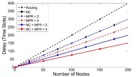
On the other hand, there are significant gains from MPR and network coding, while using the improved MAC, when considering the delay, or total time to complete all sessions. When a single packet is at every node, we determine the time for all packets to reach their intended destinations. Fig. 10 shows the total time to complete all flows within an “X” topology component, as grows. It can be easily verified that the delay gains for the MPR with or and network coding cases are approximately and respectively for large .

VI Conclusion
We have provided a lower bound to the gains in total throughput from MPR and network coding for topology components that create traffic bottlenecks in large networks. We provided an analysis of the total throughput and showed that the effectiveness of network coding is highly dependent on the use of MPR. We have shown that the combined use of MPR and network coding results in super-additive gains, rather than just purely additive gains.
In addition, we evaluated the fairness imposed by the 802.11 MAC and showed that the coding + MPR gain at saturation is not maximized. We argued that while the current 802.11 MAC is fair to nodes, it is inherently unfair to flows of information in multi-hop networks. We further generalized each scenario for both unicast and broadcast traffic.
We then used our simple, validated model to design a new MAC approach using MPR and network coding that allocates channel resources by providing a greater proportion of resources to bottle-necked nodes and less to source nodes. The new MAC overcomes the constraints of the legacy 802.11 MAC and ensures fairness among information flows rather than nodes. Our proposed approach, optimized for networks using network coding and MPR, shows an increase in the achievable throughput of as much as 6.3 times the throughput when neither network coding nor MPR is used in similar networks. Finally, we analyzed the scalability of the canonical topology components. We showed that the gains provided by the use of MPR and network coding are highly dependent on the connectivity of the network and the gains are not necessarily realized in the throughput but in the time it takes to propagate information for large networks.
References
- [1] R. Ahlswede, N. Cai, S.-Y. Li, and R. Yeung, “Network information flow,” IEEE Transactions on Information Theory, vol. 46, no. 4, pp. 1204 –1216, Jul 2000.
- [2] S. Katti, H. Rahul, W. Hu, D. Katabi, M. Médard, and J. Crowcroft, “Xors in the air: Practical wireless network coding,” IEEE/ACM Trans. Netw., vol. 16, no. 3, pp. 497–510, 2008.
- [3] F. Zhao and M. Médard, “On analyzing and improving cope performance,” in Information Theory and Applications Workshop (ITA), 2010.
- [4] S. Sengupta, S. Rayanchu, and S. Banerjee, “An analysis of wireless network coding for unicast sessions: The case for coding-aware routing,” in INFOCOM 2007.
- [5] J. Le, J. Lui, and D. M. Chiu, “How many packets can we encode? - an analysis of practical wireless network coding,” in INFOCOM 2008.
- [6] H. Seferoglu and A. Markopoulou, “Network coding-aware queue management for unicast flows over coded wireless networks,” in NetCod, 2010.
- [7] J. J. Garcia-Luna-Aceves, H. R. Sadjadpour, and Z. Wang, “Challenges: Towards truly scalable ad hoc networks,” in MobiCom, 2007.
- [8] S. Ghez, S. Verdu, and S. Schwartz, “Stability properties of slotted aloha with multipacket reception capability,” IEEE Transactions on Automatic Control, vol. 33, no. 7, pp. 640 –649, Jul 1988.
- [9] Q. Zhao and L. Tong, “A multiqueue service room mac protocol for wireless networks with multipacket reception,” IEEE/ACM Transactions on Networking, vol. 11, no. 1, pp. 125 – 137, Feb 2003.
- [10] G. Celik, G. Zussman, W. Khan, and E. Modiano, “Mac for networks with multipacket reception capability and spatially distributed nodes,” IEEE Transactions on Mobile Computing, vol. 9, no. 2, pp. 226 –240, Feb. 2010.
- [11] J. J. Garcia-Luna-Aceves, H. R. Sadjadpour, and Z. Wang, “Extending the capacity of ad hoc networks beyond network coding,” in IWCMC, 2007.
- [12] A. Rezaee, L. Zeger, and M. Médard, “Multi packet reception and network coding,” in MILCOM, 2010.
- [13] H. Abuzanat, B. Trouillet, and A. Toguyeni, “Routing fairness model for qos optimization in wireless network,” in SENSORCOMM, 2008.