Electrical Control of the Chemical Bonding of Fluorine on Graphene
Abstract
We study the electronic structure of diluted F atoms chemisorbed on graphene using density functional theory calculations. We show that the nature of the chemical bonding of a F atom adsorbed on top of a C atom in graphene strongly depends on carrier doping. In neutral samples the F impurities induce a -like bonding of the C atom below, generating a local distortion of the hexagonal lattice. As the graphene is electron-doped, the C atom retracts back to the graphene plane and for high doping (cm-2) its electronic structure corresponds to a nearly pure configuration. We interpret this - doping-induced crossover in terms of a simple tight binding model and discuss the physical consequences of this change.
pacs:
73.22.Pr,81.05.ue,73.20.-r,73.20.HbThe unusual electronic and mechanical properties of graphene, which make it an excellent candidate to build nanoscale electronic devices, have generated an intense and exciting activity during the last few years Novoselov et al. (2004); *Novoselov2005; Katsnelson et al. (2006); *Novoselov2007; *Geim2007; Castro Neto et al. (2009a); *Beenakker2008; *DasSarma2010. This two-dimensional (2D) honeycomb lattice of C atoms is a prototype of the C-C binding. The cohesion and structural stability of the lattice are mainly due to the -bonds, while the -orbitals determine its low energy electronic properties. The anomalous charge transport in pure graphene is a consequence of the chiral nature of the low energy excitations, which correspond to massless Dirac fermions Castro Neto et al. (2009a); *Beenakker2008, and its linear dispersion relation close to the Fermi energy. This leads to a strong suppression of the backscattering processes which, together with the high purity inherent to the samples, is responsible for the long electron mean-free path. Clean graphene samples can be grown because substitutional impurities, vacancies and other structural defects are quite rare due to the stability of the strong -bonds. Therefore, one of the main sources of electron scattering is the presence of adsorbed impurities. For this reason, the control and manipulation of adatoms is viewed as a possible route to modify the electronic properties and to create the appropriate conditions for charge and spin transport.
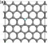
The problem of adatoms on graphene has been theoretically and experimentally studied by several groups Lehtinen et al. (2003); Duplock et al. (2004); Meyer et al. (2008); Chan et al. (2008); Uchoa et al. (2008); *CastroNeto2009a; Cornaglia et al. (2009); Wehling et al. (2009); *Wehling2010; *Wehling2010a; Castro Neto and Guinea (2009); Boukhvalov and Katsnelson (2009); Ao and Peeters (2010). It is known that impurities like H or F are adsorbed on top of a C atom—from hereupon denoted as C0—and induce a distortion of the flat honeycomb lattice. This distortion consists of a puckering of the C0 carbon as its electronic configuration changes from to another with a more character (see Fig.1). The behavior of H and F impurities on neutral graphene presents some quantitative and qualitative differences: on the one hand, the charge transfer is larger and the graphene distortion smaller for F impurities. On the other hand, there are strong indications that H creates a magnetic defect while no magnetism is obtained with F. However, spin related effects are to be expected even in the case of F impurities as the local distortion of the D plane leads, like in carbon nanotubes De Martino et al. (2002); Huertas-Hernando et al. (2006), to spin-orbit coupling Castro Neto and Guinea (2009) .

Despite this intense activity, little is known about the effect of graphene’s doping on the character of the bonding of atoms and molecules. Here, we show that carrier doping determines the structure of the defect induced by F impurities and the nature of the chemical bond. With electron-doping, the distortion of the lattice decreases and the F-C0 distance increases. Notably, for large enough doping, the F-C bonding acquires an ionic character. This effect provides an opportunity to study, in a controllable and continuous way, the evolution from ionic-like ( configuration of C0) to covalent-like ( configuration of C0) bonding of adatoms on graphene. Hole-doping, as opposed to electron doping, results in a moderate increase of the lattice distortion. These changes have important consequences on the local spectroscopic properties of the adatom and its surrounding atoms and will certainly modify the charge and spin transport properties of the system.
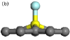
We consider a graphene layer with a unit cell of C atoms and one F atom (a concentration of F atoms). A schematic side view of the distortion induced by the F atom is shown in Fig. 1(b). Figures 1(c) and 1(d) show the partial density of states (PDOS) of an undoped graphene layer obtained using Density Functional Theory (DFT) 111DFT calculations were done with a plane wave basis as implemented in the VASP code Kresse and Furthmüller (1996); *Kresse1996 and the cutoff energy set to eV. The core electrons were treated with a frozen core projector augmented wave (PAW) method Blöchl (1994); *Kresse1999. F and C’s electrons were treated in the core. The projector radius for F was Å while for C was Å. We use the PBE generalized gradient approximation to treat the exchange and correlation Perdew et al. (1996); *Perdew1997. To correct for the dipole moment generated in the cell and to improve convergence with respect to the periodic cell size, monopole and dipole corrections were considered Neugebauer and Scheffler (1992); *Makov1995.. These results make evident that there is a large hybridization between the F and the C0 atom—the strong broadening of the F’s atomic levels is consistent with a covalent bonding. We also note that there is a narrow resonance close to the Fermi energy, similar to what is obtained for H. However, in the case of F, as opposed to the H case, this vacancy-like state does not lead to the appearance of magnetic order Usaj et al. (2010).
For a quantitative analysis of the distortion, we follow Ref. [Castro Neto and Guinea, 2009] and relate the angles between the bonds with the -character of the C0 orbitals. In terms of its and atomic orbitals, the hybrid -orbital can be written as where and correspond to the and configurations, respectively. A local basis includes the -orbitals that are also parameterized by the same constant Castro Neto and Guinea (2009). The angle between the -bonds and the -axis, perpendicular to the graphene plane, is given by . This expression interpolates between for the and for the configurations. Our results for the case of diluted F atoms on neutral graphene give and . These values indicates a dominant character of the bonds of the C0 carbon atom. They are in qualitative agreement with previous results obtained with a high F concentration but are smaller than the distortion found in F-graphene Zhou et al. (2010).
| Electrons | [Å] | [Å] | ||
|---|---|---|---|---|
| neutral | ||||
To simulate electron and hole doping we add or remove electrons from the unit cell. The extra charge is compensated with a uniform charged background. The results obtained by adding one and two electrons per DFT unit cell, corresponding to dopings of the order of cm-2, are shown in Fig. 2. The F’s PDOS shows an increasing narrowing of the resonances as the doping is increased while, at the same time, the C0’s PDOS becomes more similar to the one corresponding to a ‘bulk’ carbon atom (Cb). This indicates an important reduction of the hybridization parameter as a consequence of the new structure of the defect in the doped system. Namely, with electron-doping the C0 carbon atom retracts back to the graphene plane and the F-C0 distance increases. This change is accompanied by an increase of the charge transfer to the F atom. For the largest doping studied here, two added electrons per DFT unit cell, we obtain which gives . These values correspond to an almost pure configuration of C0. On the contrary, with hole-doping, the distortion increases and the F-C0 distance decreases, indicating an increase of the -character of the bonding of the C0 carbon atom—see Table I for details.
Hence, our results indicate that the effect of the F adatom on graphene can be strongly modified by external gates, a simple way to change doping, offering a new route to control graphene’s transport properties. For instance, as mentioned above, the local distortion of the lattice introduces a spin-orbit coupling. As discussed in Ref. Castro Neto and Guinea (2009), the effective spin-orbit coupling is roughly given by , where is the atomic spin-orbit coupling of the C atoms. Then, our results show that, as the system is doped with electrons, changes by a factor . Such a change should be clearly detected in spin dependent transport measurements.
In order to understand the physics underlying this - crossover we use a minimal tight binding (TB) model that captures the relevant features. The -bands of the graphene plane are described by a Hubbard Hamiltonian where creates an electron with spin at site of the graphene lattice, , and the first sum runs over nearest neighbors. The F impurity is bounded to the C0 atom, located at site and represented by the relevant orbital, and it is described by , where creates an electron with spin and energy at the relevant orbital of the impurity and is the intra-atomic Coulomb repulsion. The impurity-graphene interaction includes a one-body hybridization , a distortion-induced shift of the C0 energy , the interaction with the image charge Newns (1969) and a local inter-atomic interaction ,
| (1) | |||||
with and . Note that the effect of is to renormalize both the orbital energy, , and the intra-atomic repulsion, , favoring the charging of the F atom. The term, instead, takes into account the discharge induced on the C0 atom upon charging of the F atom. In what follows, guided by the DFT calculations, we take with equal to and include the reduction of induced by the distortion in the case. The energy shift of C0 is given by Castro Neto and Guinea (2009), where eV and are the energies of the and carbon orbitals, respectively. Since the parameters , , , and depend on the distortion of the lattice, and to minimize the number of free parameters of the model, we consider two frozen configurations corresponding to the two limiting cases presented above: i) the distorted lattice of Fig. 1 with , , and Ihnatsenka and Kirczenow (2010); ii) the undistorted lattice with , and —the smaller value of the hybridization reflects the larger F-C0 distance shown in Table I. In the latter case, where the graphene sheet is essentially unalterated, we can consider that the situation is reminiscent of the classical problem of a point charge in front of a conducting plate and take, as a simple approximation, with Newns (1969); Ghaznavi et al. (2010). On the contrary, in the case, the F is covalently bounded to C0 and then one expects a stronger local screening of the F’s excess charge. That is, we expect the term to be dominant. For the sake of simplicity, and to avoid a double counting of the Coulomb interaction, we take and choose . Similarly, we take . In the following, we solved the Hamiltonian in the Hartree-Fock approximation. From comparison to the DFT results for the PDOS of the F, C0 and Cn atoms we estimate the effective parameters and while we set .
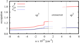
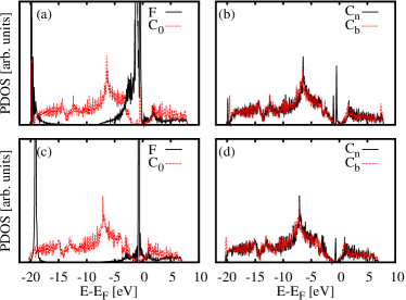
Figure 3 shows a comparison of the DFT and TB results for the PDOS projected onto the orbitals. While the latter is not expected to give an accurate description of the former, there is a good qualitative agreement between both methods for the general features of the PDOS, which gives support to the chosen effective TB parameters. Figures 4(a) and 4(b) show the occupation of the F, C0 and one of the Cn atoms as a function of the graphene’s electron density for the and configurations, respectively. In the case the F, C0 and Cn atoms are moderately (dis-)charged as the graphene is doped with electrons (holes)—note that C0 is slightly discharged when F is charged. This differs from the case where the F atom is heavily charged while the C0 and Cn atoms remain essentially uncharged. This is consistent with the DFT results, where a significant increase of the charge of the F atom is observed in the electron doped case—in addition to that, the DFT shows a small discharge of the C0 atom, which in our model can be obtained by including a small .
It is worthy of mention that the simplified model also helps to understand the absence of magnetism in the DFT calculations. This is so because the main features can be described by an even simpler model where interactions are only included on the F, C0 and Cn atoms. In that case, the system behaves as an effective Anderson impurity and then the absence of magnetism can be understood in terms of its effective parameters Usaj et al. (2010).
The mechanism behind this covalent-ionic crossover is the competition between the hydridization of the F and C0 atoms and both the distortion of the lattice and the Coulomb interaction. In the neutral case, the configuration is more stable since the energy gain due to F-C0 hybridization overcomes the energy lost due to the lattice distortion. From DFT calculations, we estimate the latter to be . Since it mainly comes from the bands this contribution is not included in our TB model—we assume it to be doping independent. Upon doping, the increase in the occupation of both the F and (enhanced in the latter case by the energy shift ) increases the energy due to the local Coulomb interaction while, at the same time, it leads to a reduction of the gain due to (‘antibonding’ states become occupied). On the contrary, the configuration, which does not pay the distortion energy, gains some energy due to when the F is charged. To verify this scenario, we calculate the energy difference between the two configurations Newns (1969), , where is a parameter that linearly interpolates all the parameters that change between the two configurations (, , , and ) and is the average value in the Hartree-Fock state. Within our TB model, we found that is roughly constant for hole doping but it drops as the graphene sheet is doped with electrons. While this Hartree-Fock result is sensitive to the chosen parameters and even though this is an oversimplified picture of the real process where the local configuration is progressively distorted by the doping (see Table I), it clearly gives further support to our interpretation the DFT results.
In summary we have shown that the nature of the F-C0 bonding changes with doping from covalent for hole-doping to ionic for electron-doping. This is followed by a change of the structure of the defect () with an important distortion of the lattice for the hole-doped system to an almost undistorted lattice for electron-doped graphene. This structural change can serve as a new knob to control graphene’s electronic properties. As mentioned before, the properties of several elements and molecules on neutral graphene have been extensively studied Chan et al. (2008); Wehling et al. (2009). Our results point out the relevance of doping and call for a more exhaustive analysis of other elements, beyond F, as they could present similar effects.
JOS and AS acknowledge support from the Donors of the American Chemical Society Petroleum Research Fund and use of facilities at the Penn State Materials Simulation Center. GU, PSC, ADH, and CAB acknowledge financial support from PICTs 06-483 and 2008-2236 from ANPCyT and PIP 11220080101821 from CONICET, Argentina. ADH acknowledges support from the Flemish Science Foundation (FWO).
References
- Novoselov et al. (2004) K. S. Novoselov, A. K. Geim, S. V. Morozov, D. Jiang, Y. Zhang, S. V. Dubonos, I. V. Grigorieva, and A. A. Firsov, Science 306, 666 (2004).
- Novoselov et al. (2005) K. S. Novoselov, A. K. Geim, S. V. Morozov, D. Jiang, M. I. Katsnelson, I. V. Grigorieva, S. V. Dubonos, and A. A. Firsov, Nature 438, 197 (2005).
- Katsnelson et al. (2006) M. I. Katsnelson, K. S. Novoselov, and A. K. Geim, Nat. Phys. 2, 620 (2006).
- Novoselov et al. (2007) K. S. Novoselov, Z. Jiang, Y. Zhang, S. V. Morozov, H. L. Stormer, U. Zeitler, J. C. Maan, G. S. Boebinger, P. Kim, and A. K. Geim, Science 315, 1379 (2007).
- Geim and Novoselov (2007) A. K. Geim and K. S. Novoselov, Nat. Mat. 6, 183 (2007).
- Castro Neto et al. (2009a) A. H. Castro Neto, F. Guinea, N. M. R. Peres, K. S. Novoselov, and A. K. Geim, Rev. Mod. Phys. 81, 109 (2009a), and refs. therein.
- Beenakker (2008) C. W. J. Beenakker, Rev. Mod. Phys. 80, 1337 (2008).
- Sarma et al. (2010) S. D. Sarma, S. Adam, E. H. Hwang, and E. Rossi, (2010), arXiv:1003.4731 .
- Lehtinen et al. (2003) P. O. Lehtinen, A. S. Foster, A. Ayuela, A. Krasheninnikov, K. Nordlund, and R. M. Nieminen, Phys. Rev. Lett. 91, 017202 (2003).
- Duplock et al. (2004) E. J. Duplock, M. Scheffler, and P. J. D. Lindan, Phys. Rev. Lett. 92, 225502 (2004).
- Meyer et al. (2008) J. C. Meyer, C. O. Girit, M. F. Crommie, and A. Zettl, Nature 454, 319 (2008).
- Chan et al. (2008) K. T. Chan, J. B. Neaton, and M. L. Cohen, Phys. Rev. B 77, 235430 (2008).
- Uchoa et al. (2008) B. Uchoa, V. N. Kotov, N. M. R. Peres, and A. H. Castro Neto, Phys. Rev. Lett. 101, 026805 (2008).
- Castro Neto et al. (2009b) A. Castro Neto, V. Kotov, J. Nilsson, V. Pereira, N. Peres, and B. Uchoa, Solid State Comm. 149, 1094 (2009b).
- Cornaglia et al. (2009) P. S. Cornaglia, G. Usaj, and C. A. Balseiro, Phys. Rev. Lett. 102, 046801 (2009).
- Wehling et al. (2009) T. O. Wehling, M. I. Katsnelson, and A. I. Lichtenstein, Phys. Rev. B 80, 085428 (2009).
- Wehling et al. (2010a) T. O. Wehling, A. V. Balatsky, M. I. Katsnelson, A. I. Lichtenstein, and A. Rosch, Phys. Rev. B 81, 115427 (2010a).
- Wehling et al. (2010b) T. O. Wehling, H. P. Dahal, A. I. Lichtenstein, M. I. Katsnelson, H. C. Manoharan, and A. V. Balatsky, Phys. Rev. B 81, 085413 (2010b).
- Castro Neto and Guinea (2009) A. H. Castro Neto and F. Guinea, Phys. Rev. Lett. 103, 026804 (2009).
- Boukhvalov and Katsnelson (2009) D. W. Boukhvalov and M. I. Katsnelson, Journal of Physics: Condensed Matter 21, 344205 (2009).
- Ao and Peeters (2010) Z. M. Ao and F. M. Peeters, Appl. Phys. Lett. 96, 253106 (2010).
- De Martino et al. (2002) A. De Martino, R. Egger, K. Hallberg, and C. A. Balseiro, Phys. Rev. Lett. 88, 206402 (2002).
- Huertas-Hernando et al. (2006) D. Huertas-Hernando, F. Guinea, and A. Brataas, Phys. Rev. B 74, 155426 (2006).
- Note (1) DFT calculations were done with a plane wave basis as implemented in the VASP code Kresse and Furthmüller (1996); *Kresse1996 and the cutoff energy set to eV. The core electrons were treated with a frozen core projector augmented wave (PAW) method Blöchl (1994); *Kresse1999. F and C’s electrons were treated in the core. The projector radius for F was Å while for C was Å. We use the PBE generalized gradient approximation to treat the exchange and correlation Perdew et al. (1996); *Perdew1997. To correct for the dipole moment generated in the cell and to improve convergence with respect to the periodic cell size, monopole and dipole corrections were considered Neugebauer and Scheffler (1992); *Makov1995.
- Usaj et al. (2010) G. Usaj, P. S. Cornaglia, A. D. Hernández-Nieves, J. Sofo, and C. A. Balseiro, (2010), unpublished.
- Zhou et al. (2010) J. Zhou, Q. Liang, and J. Dong, Carbon 48, 1405 (2010).
- Newns (1969) D. M. Newns, Phys. Rev. 178, 1123 (1969).
- Ihnatsenka and Kirczenow (2010) S. Ihnatsenka and G. Kirczenow, (2010), arXiv:1008.4111v1 .
- Ghaznavi et al. (2010) M. Ghaznavi, Z. L. Mišković, and F. O. Goodman, Phys. Rev. B 81, 085416 (2010).
- Kresse and Furthmüller (1996) G. Kresse and J. Furthmüller, Computational Materials Science 6, 15 (1996).
- Kresse and Furthmüller (1996) G. Kresse and J. Furthmüller, Phys. Rev. B 54, 11169 (1996).
- Blöchl (1994) P. E. Blöchl, Phys. Rev. B 50, 17953 (1994).
- Kresse and Joubert (1999) G. Kresse and D. Joubert, Phys. Rev. B 59, 1758 (1999).
- Perdew et al. (1996) J. P. Perdew, K. Burke, and M. Ernzerhof, Phys. Rev. Lett. 77, 3865 (1996).
- Perdew et al. (1997) J. P. Perdew, K. Burke, and M. Ernzerhof, Phys. Rev. Lett. 78, 1396 (1997).
- Neugebauer and Scheffler (1992) J. Neugebauer and M. Scheffler, Phys. Rev. B 46, 16067 (1992).
- Makov and Payne (1995) G. Makov and M. C. Payne, Phys. Rev. B 51, 4014 (1995).