Alice Alignment, Tracking and Physics Performance Results
Abstract:
The ALICE detector was designed to track and identify particles in a wide transverse momentum range, from more than down to . The innermost barrel-like detector, the Inner Tracking System (ITS), is dedicated to precise tracking and to primary and secondary vertices recontruction. In this proceeding we present the ITS performance for tracking, primary vertex reconstruction and particle identification capability. The current understanding of the detector response is the result of an extensive phase of commissioning started with 2008 cosmic-ray run and finalized with data from pp collisions: the alignment status of the three ITS sub-systems (Silicon Pixel Detectors, Silicon Drift Detectors, Silicon Strip Detectors) and the study of the detector material budget via the reconstruction of gamma conversion in the material are presented. Precise tracking is required to reconstruct and separate the primary vertex of interaction from secondary vertices from hyperons and heavy-flavour meson decays: some examples of the achieved results are shown.
1 Introduction
The ALICE detector is composed of two main sections: a central barrel, covering the full azimuth in the acceptance region and a forward () muon arm [1]. The ITS (Inner Tracking System) is a cylindrically-shaped silicon tracker in the central barrel that surrounds the interaction region. Its main task is to provide precise track and vertex reconstruction close to the interaction point. In particular, the ITS was designed with the aim to improve the position, angle, and momentum resolution for tracks reconstructed in the Time Projection Chamber (TPC, inner radius 80 ), to identify the secondary vertices from the decay of hyperons and heavy flavoured hadrons, to reconstruct the interaction vertex with a resolution better than 100 m, and to recover particles that are missed by the TPC due to acceptance limitations.
In this proceeding we present the ITS performance for tracking, primary vertex reconstruction and particle identification capability. We start by describing the ITS layout in Section 2. To preserve the design performance and to tune MC simulations in order to reproduce as realistically as possible the detector response and geometry, alignment and a good knowledge of the material budget are required. These are addressed in Section 3. The actual tracking and vertexing performance is reported in the same section: the resolution on the impact parameter in the transverse plane is used as a benchmark quantity to summarize the results. The ITS capability for particle identification at low momentum is described in Section 4. In Section 5 results of physics analyses based on the precise track and vertex reconstruction guaranteed by the ITS are shown.
2 Layout of the ALICE Inner Tracking System
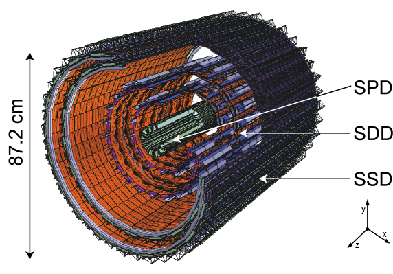
The ITS consists of six layers, with radii between 3.9 cm and 43.0 cm, covering a pseudorapidity range varying from (outermost layer) up to (innermost layer). The two innermost layers are equipped with Silicon Pixel Detectors (SPD), the two intermediate layers contain Silicon Drift Detectors (SDD), while Silicon Strip Detectors (SSD) are used on the two outermost layers. The geometrical layout of the ITS layers, as implemented in the ALICE simulation and reconstruction software framework (AliRoot [2]), is shown in Fig. 1 (left). The module local reference system is defined with the and axes on the sensor plane and the axis in the same direction as the global axis. The local direction is approximately equivalent to the global (). The geometrical parameters of the layers are summarised in Table 1. As far as the material budget is concerned, it should be noted that the values reported in Table 1 account for sensor, electronics, cabling, support structure and cooling for particles crossing the ITS perpendicularly to the detector surfaces. Another 1.30% of radiation length comes from the thermal shields and supports installed between SPD and SDD barrels and between SDD and SSD barrels, thus making the total material budget for perpendicular tracks equal to 7.66% of .
| Number | Active Area | Material | |||||
|---|---|---|---|---|---|---|---|
| Layer | Type | [cm] | [cm] | of | per module | Resolution | budget |
| modules | [mm2] | [] | [%] | ||||
| 1-2 | pixel | 3.9-7.6 | 14.1 | 80-160 | 12.870.7 | 12100 | 1.14 |
| 3-4 | drift | 15.0-23.9 | 22.2-29.7 | 84-176 | 70.1775.26 | 3525 | 1.13-1.26 |
| 5-6 | strip | 38.0-43.0 | 43.1-48.9 | 748-950 | 7340 | 20830 | 0.83-0.86 |
3 ITS performance for track and vertex reconstruction
The precise reconstruction of track trajectory, of beam interaction point and of decay points of unstable particles is a key element for ALICE, of fundamental importance for the fulfilment of its physics programme. A benchmark quantity to represent track and vertex reconstruction performance is the resolution on the impact parameter in the transverse plane, , defined as the distance between the projection of a track in the transverse plane and the reconstructed position of the primary vertex. For instance, most of heavy-flavour analyses rely on the capability of identifying secondary tracks, coming from charm and beauty hadron decays, displaced from the primary vertex. The “resolving power” needed is dictated by the impact parameter typical of these tracks: as an example, for the kaon and pion tracks coming from a decay. This value must be compared with the impact parameter resolution, which is determined by the precision of track reconstruction and extrapolation to the primary vertex. Due to multiple scattering, the material budget determines the transverse momentum trend of the impact parameter resolution and the dependence on the particle mass. The detector resolution, along with the detector layout, adds a independent contribution determining the asymptotic value of the resolution. The intrinsic detector resolution, determined by the sensor structure and response, accounts for the uncertainty on the hit position on the sensor. A further contribution derives from misalignment, that is, from the uncertainty of the detector position in the global reference system where tracking is performed. The track model adopted for track reconstruction, in particular relative to the treatment of the interaction with the material (energy loss, multiple scattering) can influence the reconstruction and extrapolation of track trajectory. The contribution of the uncertainty on the reconstructed primary vertex position depends on the event multiplicity () and is generally not constant in (high tracks are produced more copiously in high multiplicity events). MC simulations must reproduce as realistically as possible the detector response and geometry, the material budget and the residual misalignment to prevent large systematic errors to arise. In this section all the above issues are addressed.
3.1 Study of material budget amount with gamma conversion
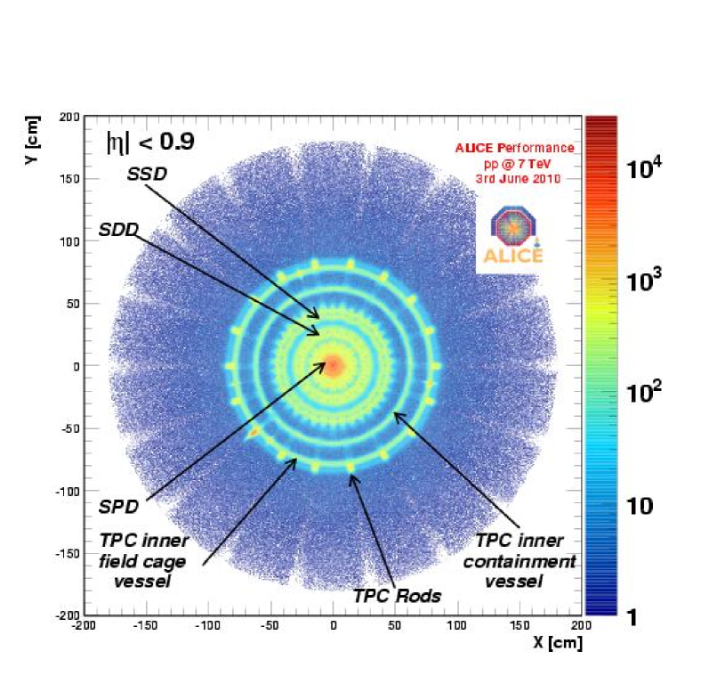
The dependence of photon conversion probability on the radiation thickness of a detector element has been exploited to obtain a detailed “tomography” of the detector by studying the distribution of the conversion points. In Fig. 1 (right) the two-dimensional (xy) distribution of gamma conversion points obtained with pp collisions at is shown. Gamma conversion candidates are obtained via the V0 topology identification which is performed during the track reconstruction. The electron and positron daughter tracks are further selected using the TPC PID information. Vertex and mass constraints are applied as well. The coordinates of the conversion point are recalculated imposing that the daughter tracks are parallel at the conversion point. The current simulation reproduces the amount and the spatial distribution of reconstructed conversion points in great detail, with a relative accuracy of a few percent.
3.2 Alignment of the Inner Tracking System
The position and orientation in space of each of the 2198 ITS modules are defined by the six parameters of a roto-translation: more than 13000 parameters must be determined to align the entire ITS. The sources of alignment information are the survey measurements (for SDD and SSD) and the reconstructed space points from cosmic-rays and collision particles. These points are the input for the software alignment methods, based on global or local minimization of the residuals.
The adopted strategy for the ITS is outlined as follows: the first step is the validation of the SSD survey measurements with cosmic-ray tracks; then the alignment of SPD and SSD is performed with cosmic-ray tracks, without magnetic field; the already aligned SPD and SSD are used to confirm and refine the initial time-zero calibration of SDD, obtained with SDD standalone methods; in the meanwhile the SDD survey measurements with cosmic-ray tracks are validated; then the full detector (SPD, SDD, SSD) is aligned with cosmic-ray tracks, including also data collected with magnetic field ; tracks from pp collisions with both and are used together with tracks from cosmic-rays to complete and improve the alignment. The relative alignment of the ITS to the TPC is performed in the meanwhile.
The results achieved with cosmic-ray data collected in 2008 are described in [5, 6, 7]. About tracks from cosmic-ray events with magnetic field off were considered for the ITS alignment. Cosmic-ray tracks have a dominant vertical component and the sides of the barrel layers have limited statistics. Tracks from proton-proton collisions, with both magnetic field off and , are now used to align the remaining SPD modules (poorly illuminated by cosmic-rays) and to monitor and improve the alignment quality of the whole ITS.
The following three observables are used to check the quality of the alignment: the track-to-point residual, the track-to-point distance for “extra” points in the acceptance overlaps and, with cosmic-ray tracks only, the top half-track to bottom half-track matching at the plane (). The latter provides a direct measurement of the resolution on the track transverse impact parameter , namely . The pairs of points produced by particles crossing the acceptance overlap between two neighbouring modules allow us to verify the relative position of the modules themselves. On average, they allow to estimate the effective spatial resolution of the sensor modules, i.e. the combination of the intrinsic spatial resolution and the residual misalignment. Since the two “extra” points are rather close in space and the amount of material crossed by the particle in-between the two points is very limited, multiple scattering can be neglected for tracks of high enough momentum. The dependence of the intrinsic sensor resolution on the track-to-module incidence angle has to be accounted for. A different incidence angle implies a different path in the silicon material and, depending also on electronic thresholds, a different cluster shape. The error on can be related to the effective spatial resolution of the two points, , as:
| (1) |
where the 1 and 2 subscripts indicate the two overlapping points, is the (unsigned) incidence angle of the track on the module plane and is the relative angle between the two module planes. For overlaps between modules on the same ladder (i.e. along the z direction) while, for overlaps between modules on different ladders (i.e. in ), and in the inner and outer SPD, and in the inner and outer SDD, and in the inner and outer SSD.
In the following we briefly review the alignment status of the three sub-detectors. The average residual misalignment is summarized by the values reported in the second row of Table 2.
3.2.1 Status of SPD alignment
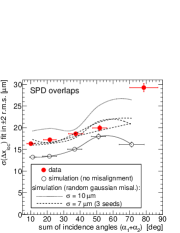
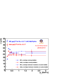
Two algorithms, both based on the minimization of track-to-point residuals, have been used to align the SPD with tracks from cosmic-rays: the main one, based on the Millepede algorithm [8], performs a global minimization of all alignment and track parameters in the same time while the other performs a module-by-module minimization and is iterated to account for the correlations among the parameters recovered for the different modules [5, 6]. The alignment quality as well as the values of the alignment parameters obtained with the two methods are comparable. About of the SPD modules were aligned within the target of containing the worsening of spatial resolution due to misalignment within of the nominal resolution. The remaining modules have been aligned with pp data. Residuals from cosmic-ray tracks and pp tracks are used together, with different weights, in the Millepede algorithm to exploit the different module correlations in the two samples. Figure 2 (left) shows the spread of the distribution as a function of the sum () of the incidence angles on the two overlapping modules, as obtained with tracks from cosmic-rays in 2008. Monte Carlo simulation results are reported for comparison. The 2008 data are well described by the simulation with a random residual misalignment with . On the right panel in the same figure, obtained with data from pp at , the spread of the is reported as a function of . The rise at low is caused by multiple scattering, whose effect becomes negligible for . Data points are compatible within errors with the results from a Monte Carlo simulation obtained using random gaussian misalignments with . This value can be considered an estimate of the average level of residual misalignment for all the SPD modules. Further studies are now in progress to fully understand the intrinsic detector resolution and to address correlations among misalignments, not detectable with this observable.
3.2.2 Status of SSD alignment
The survey measurements performed during SSD assembly and mounting phases assured a satisfactory first-alignment status for this detector. The survey was carried out in two stages: the measurement of the positions of the modules on the ladders and the measurement of the positions of the ladder endpoints on the support cone. The modules are mounted with a small (2 mm) overlap in both the longitudinal (, modules on the same ladder) and transverse directions (, adjacent ladders). The residuals between the “extra” points in these overlaps have been studied with tracks from cosmic-rays as well as from pp events. In Fig. 3 (left) the spread of distribution obtained with pp data at 7 is shown as a function of , separately for overlaps between modules along the same ladder (filled markers) and for overlaps between different ladders (empty markers). For the latter, the effect of multiple scattering at low is more evident because of the larger distance between the overlapping modules. The distributions obtained with MC simulations seem to slightly overestimate the residual misalignment. The module and ladder residual misalignment in the simulations was set by extracting randomly, according to a uniform distribution, smearing values for the module and ladder alignment parameters. On the basis of the survey and of the alignment quality estimated with cosmic-ray tracks, the values were chosen so that the overall maximum displacement could not exceed, for any point on a ladder, in , in , in due to module misalignment and in , in , in due to ladder misalignment. We are now investigating whether the drop at low , observed for overlaps on the same ladder, is related to a better determination of the cluster centre-of-gravity: due to the larger curvature, low tracks have a larger incidence angle than high tracks and can cross more neighbouring strips. A study of track-to-point residuals and of distribution was also performed with 2008 cosmic-ray data [7]. The residual misalignment is estimated to be for the module position on the ladder and for the ladder positions.
3.2.3 Status of SDD alignment
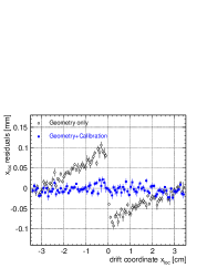
The alignment of the SDD detectors for the coordinate (reconstructed from the drift time) is complicated by the interplay between the geometrical misalignment and the calibration of drift velocity and minimum drift time . The parameter accounts for the delays between the time when a particle crosses the detector and the time when the front-end chips receive the trigger signal. The is determined by running the Millepede minimization with the as a free global parameter for each of the 260 SDD modules. Similarly, the drift velocity is considered as a free parameter for those SDD modules (about 35%) with mal-functioning injectors [4]. An example is shown for a specific SDD module in Fig. 3 (right), where the residuals along the drift direction are shown as a function of . The clear systematic shift between the two drift regions ( and ) is removed when also the calibration parameters are fitted by Millepede (square markers). For the fraction of modules for which the drift velocity is well understood the current “effective” resolution on the local coordinate has been evaluated to be . We are now completing the alignment and calibration of the remaining modules.
3.3 Performance of track reconstruction
Track reconstruction is performed via a Kalman filtering algorithm [1, 9]. Charged tracks are parametrized by 5 parameters describing a helix. In the Kalman filtering approach the track trajectory is only locally a helix: the track parameters are updated at each point along the track trajectory allowing the possibility to account for deviations due to the interaction with the material (energy loss, multiple scattering). Starting from some initial approximation for the track parameters, points to be added to the track are looked for into a search-road determined by the uncertainty on the track extrapolation at a given plane and on the cluster position uncertainty at the same plane. An additional uncertainty on the ITS cluster position has been added to the intrinsic resolution to account for residual misalignment. The adopted values, reported in Table 2, were chosen in order to optimize track reconstruction efficiency and precision.
| SPD1 | SPD2 | SDD1 | SDD2 | SSD1 | SSD2 | ||
| active modules [%] | 75-80 | 82-89 | 91 | 90 | 92 | 89 | |
| residual misalignment level | r [] | ¡10 | ¡10 | 60 | 60 | ¡15 | ¡15 |
| z [] | negl. | negl. | 50 | 50 | 100 | 100 | |
| additional error in tracking | r [] | 10 | 30 | 500 | 500 | 20 | 20 |
| z [] | 100 | 100 | 100 | 100 | 500 | 500 | |
Track reconstruction is performed in the following steps. The first one is the computation of the primary vertex using SPD tracklets. Track reconstruction then starts in the TPC (inward), using the outermost pad rows and the computed primary vertex position as seed, and continues in the ITS (inward), matching TPC reconstructed tracks to the SSD layers and following them down to the innermost SPD layer. The next step is track back-propagation, to the outermost layer of the ITS, to the outermost radius of the TPC and, after the extrapolation and the track finding in the TRD, to the outer layers (TOF, HMPID, PHOS, EMCal) for Particle IDentification (PID). A “refit” is then performed: reconstructed tracks are re-fitted inward in TRD, TPC, ITS and are propagated to the primary vertex reconstructed in the first step. Finally the primary vertex is recalculated with optimal resolution using reconstructed tracks.
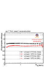
To extend the acceptance down to , an ITS-standalone tracking has been developed to reconstruct tracks in the ITS detector alone [10]. In Fig. 4 (left) the prolongation efficiency between TPC and ITS is reported as a function of transverse momentum. It is above and almost flat in the whole momentum range, if tracks with at least two points in the ITS are considered. It drops down to if the further request of one point in the SPD is done, due to the inactive modules in this detector (Table 2). MC simulations reproduce the efficiency trend observed in data within in the range .

3.4 Performance of primary vertex reconstruction
The z coordinate (along the beam line) of the interaction point is distributed in a range of several centimetres. The beam spot size in the transverse plane varies between ten and hundred microns depending on the beam optics () and energy. Two algorithms [11] are used to reconstruct the primary vertex position. The first exploits the correlation between pairs of points in the SPD (”tracklets”). The efficiency reaches with a tracklet multiplicity of 4 and approaches 100% when the tracklet multiplicity is 8. When the calculation of the full 3D position fails, the z coordinate alone is calculated: in this case one tracklet is sufficient to get a 100% efficiency.
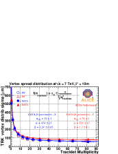
The second algorithm is based on the straight line approximation of fully reconstructed tracks in the vicinity of the vertex. With a tracklet multiplicity of 3 the reconstruction efficiency is if the information of the beam spot position and size is used to constrain the vertex, otherwise; 100% is approached at higher multiplicity. In Fig. 4 (right) the spread of the reconstructed x and y coordinates as a function of the SPD tracklet multiplicity in the event is reported. The curves flatten with higher multiplicity, corresponding to a better determination of the primary vertex position. Monte Carlo points are in good agreement with data. Data points are fitted with the function : describes the asymptotic value of the curve, determined by the size of the beam interaction diamond along the considered axis, while the second term represents a parametrisation of the primary vertex resolution as a function of the tracklet multiplicity.
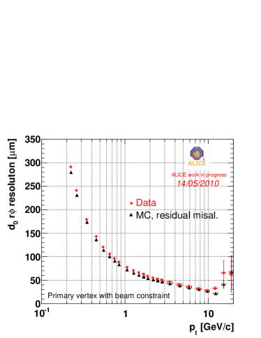
3.5 Impact parameter resolution
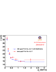
The distribution of the track impact parameter with respect to the reconstructed primary vertex is the convolution of a detector resolution function with the unknown true impact parameter distribution, the latter giving rise to relevant tails due to secondary particles. Therefore, in order to estimate the resolution on the impact parameter, only primary tracks should be considered. It has been checked that the contribution of secondaries in a range RMS produces almost negligible effects on the standard deviation obtained by fitting the impact parameter distribution in this range. This standard deviation can be considered a good estimate of the impact parameter resolution. Recently we considered the opportunity to fit the distribution in a larger range using an exponential function to describe the tails. The two methods give compatible results. To obtain an unbiased evaluation of the impact parameter, the primary vertex position is recalculated track-by-track excluding the current track from the computation. In Fig. 5 (left) the impact parameter resolution as a function of transverse momentum is shown. The obtained curve is the result of the convolution of the track position and the primary vertex resolutions. The agreement with MC is within . Further improvement is expected with alignment fine-tuning and when the material budget will be under control to per cent level.
4 Particle Identification with the SSD and SDD
The analogue readout of the electronic signal produced in the SSD and SDD detector allows for the measurement of the energy loss () in the silicon layers [4]. This information is used for particle identification at low momentum, in the non-relativistic region. Since the energy losses are distributed according to the Landau distribution, characterized by a long tail towards high energy loss values, a truncated mean is performed. In Fig. 5 (right) the truncated mean is shown as a function of momentum times the particle charge. A special correction for the different path lengths inside the silicon has been applied. The bands of kaons, pions and protons are clearly visible and centred around the continuous lines representing the theoretical curves from the Bethe-Block formula for the average energy loss. The ITS allows for hadron separation below , a region outside of TPC and TOF PID capability. Good separation between pions and kaons is achievable up to and between proton and pions up to .
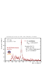
5 Examples of physics performance: rediscovery of the familiar strange and charm world
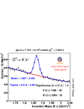
Since the first pp collisions at in November 2009, the ITS has covered an important role in all the physics analyses ongoing, from the study of the global properties of the event (multiplicity, spectra, proton/anti-proton ratio) to the reconstruction of V0 topologies and cascades up to the “rediscovering” of charmed mesons. In Fig. 6 (left) an example of the invariant mass distribution of candidates obtained with minimum bias events from pp collisions at is shown.
On the right panel in the same figure, the invariant mass distribution of candidates for is shown as obtained with minimum bias events. The (branching ratio ) is among the most promising channels for the measurement of open charm production at mid-rapidity. The detection strategy is based on an invariant mass analysis of all the pairs of tracks with opposite charges. To cope with the large combinatorial background, displaced-vertex topologies are looked for, i.e. tracks displaced from the primary vertex are selected and good alignment between the reconstructed meson momentum and its flight direction is required. At the moment of writing this proceeding ALICE observed the signal of charm mesons in the , (), decay channels, in the range . Precise reconstruction of the primary vertex and of the track trajectory in the vicinity of the vertex are essential prerequisites to perform these analyses: the performance of the ITS is thus crucial.
6 Summary
After a two year long phase of commissioning, started with 2008 cosmic-ray run and finalized with pp collisions, the ITS is in a good shape as far as concern the understanding of the detector response, the alignment and the description of the material budget. The performance on the track and vertex reconstruction are close to the nominal one and reproduced by MC simulation within a few percent. The ITS capability to identify particles down to has been shown. The ITS will cover a fundamental role in the fulfilment of ALICE physics targets as already done for the first three ALICE papers [12] based entirely on the ITS and trigger detectors.
References
- [1] K. Aamodt et al. [ALICE Collaboration], JINST 3 (2008) S08002.
- [2] ALICE Off-line framework, AliRoot, http://aliceinfo.cern.ch/Offline
- [3] R. Turrisi, “Alice Pixel Operations and Performance”, theese proceedings.
- [4] M. Sitta and P. Christakoglou, “Operations and performance of the Silicon Drift and Silicon Strip Detectors of the ALICE experiment”, theese proceedings.
- [5] ALICE collaboration 2010 JINST 5 P03003.
- [6] C. Bombonati et al., ALICE Internal Note 2009-035 (2009).
- [7] A. Dainese et al., ALICE Internal Note 2009-045 (2009).
- [8] V. Blobel and C. Kleinwort, contribution to the Conference on Advanced Statistical Techniques in Particle Physics, Durham, March, 18–22, 2002.
- [9] B. Batyunya, Yu. Belikov, K. afaík, ALICE Internal Note, ALICE-INT-97-24 (1997).
- [10] E. Crescio, A. Dainese, M. Masera and F. Prino, ALICE Internal Note 2009-046 (2010).
- [11] E. Bruna et al., ALICE Internal Note 2009-018 (2009).
-
[12]
K. Aamodt et al. [ALICE Collaboration], Eur. Phys. J. C 65 (2010), 111-125.
K. Aamodt et al. [ALICE Collaboration], Eur. Phys. J. C 68 (2010), 89-108.
K. Aamodt et al. [ALICE Collaboration], Eur. Phys. J. C 68 (2010), 345-354.